Since several Sawppy V1 builders modified their rovers for control via classic radio control transmitters, I wanted to explore doing the same with Micro Sawppy Beta 3. I don’t intend it to be the main, or even recommended, way to control a little rover. But I wanted it available as an option. Besides, I’m curious what such work would entail and thought it would be fun to try, this novelty is why I tackled the challenge first.
In preparation for this project, I modified my Spektrum SR300 radio receiver so it is easier for me to plug other things into it, not just official RC servos and speed controls. Immediately after reassembly I verified I didn’t break it with a quick test. Using affordable commodity micro servos which didn’t have the special beveled plugs. I couldn’t plug them in before, but now I could.
Eventually I’ll have wires connecting this servo to the ESP32 brain of my micro Sawppy rover, but before I do that I wanted to understand exactly what I will be working with. Having worked with hobby servo motors for many projects, I have a fair idea what their control signals are like. But all of my previous projects were about emitting these control signals, this is the first time I will listen to signals generated by another device.
This is a task that can be done several different ways. One way is to use an oscilloscope, which can plot out the signal waveforms. But to my understanding, the best tool for this job is a signal analyzer. This is a tool I’ve wished I had on my workbench. I’ve been saving up for a Saleae Logic 8 and this is the first chance to put one to use. Taking a peek at the servo control signals of a SR300 is a breeze for a Logic 8, it’s just a simple Hello World to help me get my feet wet using this piece of equipment.
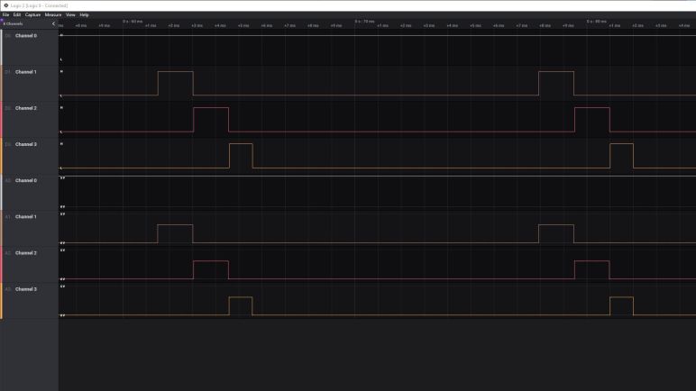
I powered the SR300 receiver with four AA batteries, and connected Saleae probes as follows:
- Channel 0 on the positive voltage supply pin, to monitor any fluctuation of battery power.
- Channel 1 on the steering servo signal pin.
- Channel 2 on the throttle servo signal pin.
- Channel 3 on the auxiliary channel servo signal pin.
Walking through traces of me fiddling with the DX3E transmitter, I found the following:
- Pulse width of each control high signal ranged from 1 to 2 milliseconds, exactly conforming to RC convention.
- The pulses are coming in faster than I had expected. Standard convention is for RC control pulses to arrive every 20 milliseconds, which translates to 50Hz. SR300 pulses are arriving every ~16.4 milliseconds, which translates to a bit over 60Hz. The ~16.4 milliseconds is measured from rising edge to rising edge of the steering signal, this matters because of the next item.
- Pulses arrive sequentially. Steering first, then throttle, then aux. The throttle control signal rising edge doesn’t start until shortly after the steering signal’s falling edge. This means if the steering signal is short, the throttle signal may start a little sooner than 16.4ms after the previous throttle signal. (At least for that one frame.)
- There is no measurable dip in input voltage. Unsurprising but comforting to confirm the receiver draws minimal power and does not drag down battery voltage as it sends out pulses.
- Pulse high is three volts. This was a surprise to me, I had expected the control IC to toggle a bank of transistors which will send out pulses at the same voltage level as the battery supply voltage. I had a feeling my expectation was wrong when I disassembled the SR300 and looked over its circuit board, and now I have confirmation on the Saleae trace: battery supply voltage of over five volts still generated control signal of a rock-steady three volts.
The last bullet is great news. I had planned to build a voltage divider out of resistors for the ESP32 to read these control pulses, and I wanted to measure pulse high in order to calculate the appropriate resistance values. The fact these are rock steady three volt signals meant that work is unnecessary, I could wire these control signal pins directly to input pins of an ESP32 without exceeding its maximum input voltage of 3.3V.
Is thee volt pulse high common across all RC receivers? That I don’t know. Anyone else who wants to wire a RC receiver to their micro servo should also measure the pulse high voltage to see if they need to drop the signal voltage. But for now it means I have confidence I have the hardware in place and can work on software.
