I took apart a LG LCD panel LP133WF2(SP)(A1) hoping to salvage something useful. After I failed to salvage the polarizer film, my hope lies with the backlight module. Its diffuser had a multi-layer construction I didn’t understand but found fascinating and wanted to see it light up firsthand. And if I am to do that, I need to figure out how to send power to the backlight LEDs. When I split the panel into the display and backlight modules, I saw the backlight was connected by a ribbon cable with seven conductors. Six of them look identical, and the seventh was wider than the rest, making it a good candidate for either a common anode or a cathode. Which is it, though? For that I looked for hints on the display panel’s integrated driver board.

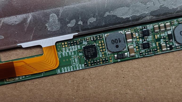
There were three significant-looking ICs on board. The largest is closest to the connector to the rest of the laptop and the top two lines written on it were “LG Display ANX2804”. I found no information on this chip online. In the middle of the circuit board is another IC, this one labeled “SM4037 DA1422 AMER038”. I found no information on this particular designation, either. (There exists a SM4037 from Fairview Microwave, but it is a connector and not a microchip.) That leaves the chip closest to the backlight connector as the best candidate for a LED driver, and luckily its markings of TPS 61187 match that of a Texas Instruments WLED driver. I think this is it.
Reading its publicly available datasheet reinforced it is the right result, as its “typical application” diagram shows the chip driving six parallel strings of LEDs. The schematic indicates the six strings are connected to a common anode with their own individual cathodes wired to one of six current sinks on the chip. This information is enough for me to wire up this array to my bench power supply to find the right voltage for this string and create my own LED driver circuit. But since I have the datasheet already on hand and a “I know it used to work” backlight control board, I kept reading to see if I could perhaps reuse the board as well.
It looks pretty promising. There are no handshake or control protocol involved, all the potential configurations for this chip are done via resistance values to certain pins which would be already present in this case. I think for a bare minimum setup I only need to provide a power source and a PWM signal to control brightness. I could also connect the enable pin but I think I could get away with using a pull-up resistor. And under this minimalist plan I would be ignoring the fault signals. Plus one very important lesson about its power supply I had to learn first.
