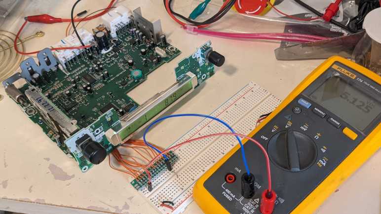
I have on hand electronic circuit boards of the factory stock tape deck unit 86120-08010 from a 1998 Toyota Camry LE. There is a connector between the main board and the faceplate, and I’ve soldered a row of wires so I can take a peek into its inner workings. I thought it might be fun to reuse the faceplate for my own project, creating something that could stand in for the main board.

Thankfully, the faceplate side connector was mostly labeled, including the ground pin which gave me a reference point for measuring all the other wires with a voltmeter. Here’s what I found:
[UPDATE: This was my first draft, see the wrap-up post for final draft.]
| Perfboard | Connector | Voltage |
|---|---|---|
| A | ACC5V | Steady 5V |
| B | LCD-DO | Steady 5V |
| C | LCD-DI | Fluctuates |
| D | LCD-CLK | Fluctuates |
| E | LCD-CE | Fluctuates |
| F | (CD-EJE?) | 5V |
| G | ILL | 0V when mainboard ILL is 0V (lights off) 12V when mainboard ILL is 12V (lights on) |
| H | (CD-BL?) | 7V when radio is on 8V when radio off. |
| I | VOL.CON | Volume knob potentiometer 0V counterclockwise limit 5V clockwise limit |
| J | PULS-A | Quadrature encoder for settings knob. 5.1V – 0.1V – 5.1V as knob is turned. |
| K | PULS-B | Quadrature encoder for settings knob. 0.1V – 5.1V – 0.1V as knob is turned. |
| L | GND | 0V reference |
| M | ILL- | 0V when lights off 0.7V when lights on |
| N | BL- | 0.7V when radio on 7.5V when radio off |
| O | RESET | 0V |
| P | ? | 0V |
Notes:
- One connector, which I wired to breadboard column P, has no label. It doesn’t seem to do much, either. Possibly unused?
- The bottom ~1/3 of two labels were cropped off this silkscreen design. The one I wired to perfboard F might be “CD-EJE”, and H might be “CD-BL”. But it may as well be “CD-BI” or similar letters with the same top 2/3.
- I was surprised that LCD-DO appears to hold steady at 5V, I expected it to fluctuate during data transfers. [UPDATE: This is expected for Sanyo CCB protocol in absence of event notification.]
- LCD-DI, LCD-CLK, and LCD-CE fluctuates as expected.
- There are two knobs on this control panel. They can be both turned and pressed. Turning the volume knob affects VOL.CON, but the press (radio power on/off) seems absent from this connector.
- Similar story with the settings knob. Turning it affects PULS-A and PULS-B but pressing (select) is absent from the connector.
- I know there is an LCD controller chip on this faceplate circuit board with additional feature to scan for button presses. Perhaps in addition to faceplate buttons it is responsible for reading presses on volume and settings knob? [UPDATE: Hypothesis confirmed.]
- If the LCD controller chip lacks ADC (analog-to-digital conversion) and quadrature decoding, that would explain why the connector has VOL.CON, PULS-A, and PULS-B so something on the mainboard can interpret knob motion.
- Several LEDs scattered throughout the faceplate turn on when ILL is high. Varying ILL between 9V and 12V controls brightness of these LEDs.
- ILL does not control LCD backlight LEDs, whose brightness remains constant. Might the LCD control chip responsible for the backlight as well?
- ILL- is a voltage plane that can be 0.7V higher than the GND plane. Have to keep this in mind when wiring up components, in case a 0.7V difference is problematic. Or ILL and ILL- could be wired separately from digital logic aspect of the circuit.
Next step: find more information on the traffic moving on LCD-DI/DO/CLK/CE pins.
