Window Shopping ESP32 Pulse Counter (PCNT)

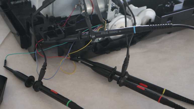
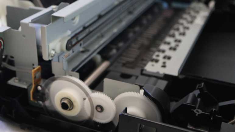
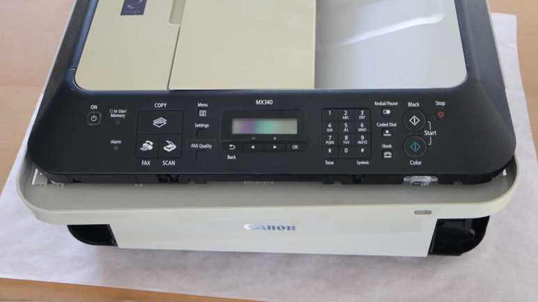
To help me understand internal workings of a Canon Pixma MX340 multi-function inkjet, I would like some signal analysis tools. Specifically for recording data coming from a quadrature encoder attached to the paper feed motor gear train. After I found out Saleae Logic could not do this, I started reading about sigrok. Thanks to a documented protocol, sigrok could run with not-officially-supported data acquisition hardware such as an ATmega328 Arduino or ESP32.

It started to look like too much of a distraction, though, so I refocused on my specific problem at hand: I just need quadrature decoding. And for that specific purpose, ESP32 has a hardware peripheral for the job. Pulse Counter (PCNT) can certainly do what its name says and count pulses on a single input, but it can be more general than that. Espressif designers had added provision for PCNT to act in response to multiple inputs and configure their interaction. One specific configuration, demonstrated in an official example, turns PCNT into a quadrature decoder.

For my purpose I need something that can keep up with quadrature phase changes of this encoder, roughly on the order of 10-20 kHz. I found a forum thread ESP32 pulse counter speed (max frequency) which says PCNT can keep up with signals up to 40MHz. That’s plenty fast for my needs!

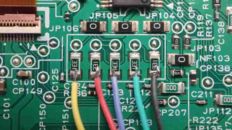
In fact, that might be too fast. At that high rate of sensitivity, small changes — like the little dip visible in one phase when the other phase is pulled to ground — may register with PCNT and that would spell trouble. Fortunately Espressif engineers thought of that too: PCNT includes an optional glitch filter to reject signals changing outside of its configured speed range. This may be an useful tool in my toolbox if I see spurious data.

ESP32 PCNT looks like a promising approach for me to build the tool I want. I would have to install ESP-IDF (probably in VSCode Extension form) before I could compile the official sample and start modifying it for my needs. Seems pretty easy on paper, but then I realized I had an even easier option I should try first.


This teardown ran far longer than I originally thought it would. Click here to rewind back to where this adventure started.

Notes on Arduino and sigrok

I want to better understand the motions made by motors in a Canon Pixma MX340 multi-function inkjet, and thought I might be able to gain insight by recording data output by a quadrature encoder attached to its paper feed motor. Finding my Saleae Logic analyzer’s software isn’t up for the job, I searched for alternatives and found sigrok. The open source signal analysis software.

In addition to quadrature decoding capability, sigrok has another advantage: lack of hardware tie-in. I looked for names I recognized on the list of supported hardware and found a few. Curiously the list continues onward to “Work in progress/planned” hardware, and that list included an entry for Arduino. Wow, really? A humble hobbyist-accessible microcontroller can act as data acquisition hardware for sigrok?

Reading that page, I believe the answer is “kinda… well, actually… no.” The basic idea is that (1) sigrok supports any signal acquisition hardware that can report data via SUMP protocol and (2) people hare written Arduino sketches that tell the ATmega328 chip to sample its IO pins and report their state that way. Unfortunately, based on information on that page, the situation is a mess. Sounds like an Arduino could work for certain scenarios but not others. A user would need to understand implementation details in order to know its limitations, and would need to understand ATmega328 to know workarounds. It’s not a plug-and-play solution and the Wiki page has not been edited since September 2020. I don’t think this will ever graduate to “supported” status.

Still, I was glad to see this work targeted the ATmega328. The original chip at the heart of original Arduino boards. I had half expected it to require a much newer processor with Arduino core support. Speaking of which, I searched for ESP32 + SUMP and found the esp32_sigrok project by GitHub user Ebiroll, along with a corresponding thread on ESP32 forums. This project also has known problems and the last commit was over three years ago.

Based on these findings, I got the distinct feeling building signal acquisition system from general-purpose hardware is really hard. Fortunately, for my purpose today I do not need general purpose capability. I can focus on just quadrature decoding and it turns out ESP32 was designed with a peripheral ideally suited for the task: pulse counter (PCNT).


This teardown ran far longer than I originally thought it would. Click here to rewind back to where this adventure started.

Logic Analyzer Quadrature Decoder

I would like to record internal behavior of a Canon Pixma MX340 multi-function inkjet, specifically the paper feed roller position encoder and two photo interrupter sensors. The sensors are binary on/off affairs that change relatively infrequently, so they should not be a challenge. The interesting element would be the quadrature encoder, reporting how far and how fast the paper feed roller motor is turning that shaft.

A rough calculation told me I need something that can sample two encoder outputs at a rate of at least 20 kHz. My Saleae Logic 8 hardware is advertised to sample at speeds up to 100 MHz. Maximum sampling rate drops if it needs to cover more channels, but 2 channels should be good for 50MHz for plenty of headroom. Unfortunately Saleae’s Logic 2 software does not perform quadrature decoding. I don’t know why I had assumed it would be part of the analysis toolkit, but I did, and so I was surprised to find it absent. A quick online search confirmed quadrature decoding is still on their “user requested feature” list for some undefined time in the future. And as I established earlier, Saleae’s analyzer extension framework doesn’t support writing my own decoder across multiple channels.

During this search for quadrature decoding support in logic analyzers, I came across mentions it was a capability in sigrok, forwarding to a terse page in sigrok documentation. I understand sigrok to be (very) roughly analogous to Saleae’s Logic 2 software, with support for lots of different hardware performing a wide variety of tasks. Perusing sigrok hardware support page I saw two names I recognized. Bus Pirate is listed as supported, but very limited due to its basic hardware. GreatFET One is also on the list, and it has a much more robust list of capabilities. I consider this a good reason to add GreatFET One to my investigation list for future purchase. If quadrature decoding analysis becomes a recurring need, it would be enough to motivate me to switch from Saleae’s proprietary solution to an open-source alternative.

Another advantage of sigrok’s open source nature is that, unlike Saleae’s proprietary solution, the software is not tied to the hardware. Not even officially supported hardware. It has support for documented interface protocols like SUMP, so any hardware can theoretically act as signal acquisition hardware for sigrok. However, this is apparently easier said than done.


This teardown ran far longer than I originally thought it would. Click here to rewind back to where this adventure started.

Canon Pixma MX340 Paper Feed Motion Recording Objectives

I have my old Canon Pixma MX340 multi-function inkjet in several pieces, but still linked with wires in running condition. I know that as I take this thing further apart, I will eventually reach a point where it no longer runs. Before that happens I would like to record motion of the paper feed motor, which actuates multiple different mechanisms (not just feeding paper) via a series of mechanical systems I want to understand. For this exercise, I want to gather enough data so I could plot behavior of several sensors on the same timeline.

The first and most obvious data source is the quadrature encoder attached to one of the shafts in this system.

On my first pass, I looked at encoder waveform during system startup under an oscilloscope, which told me it is a device operating at 3.3V DC logic level. During its startup sequence, quadrature state changes can occur in less than 100 microseconds. This is probably close to the maximum speed of this system, seeing how the signal took roughly 20 microseconds just to stabilize.

As a ballpark guess, this tells me I want to sample at least once every 50 microseconds (20 kHz sampling rate) just to ensure I don’t miss any pulses. And obviously if I want to calculate rotational speed from time between pulses, I would need a far higher sampling rate. I don’t think that’ll be necessary, though, given I didn’t notice many speed changes in this system. It’s probably good enough (and much easier) to calculate speed by counting number of pulses within a much longer time period.

On the same timeline, I want to plot the state of the photo interrupter sensor under this small circuit board. It sits above a geared mechanism driven by the same motor, and one of the gears has a partial disc that blocks this beam in certain positions. I’m sure it provides feedback into operating… whatever that is.

Less important is another photo interrupter sensor sharing the same wiring harness as above. I’m pretty sure it tells the printer when a sheet of paper has been successfully fed into the print path, but I thought it’s worth getting confirmation. The incremental work to add this data point shouldn’t be much, but I’m willing to abandon it if complications arise.

The stretch goal is to also include print carriage horizontal motion encoder into the same data stream. If successful, it would give me full information on print engine motion. However, this encoder is buried within the print carriage behind ink cartridge interfaces. I haven’t figured out how to tap into its signal yet. Getting to that circuit board may damage something beyond repair, so it is definitely not part of the first draft plan.

I think that’s a fair outline of what I want to accomplish. The obvious next question is: how might I accomplish this?


This teardown ran far longer than I originally thought it would. Click here to rewind back to where this adventure started.

Canon Pixma MX340 Paper Feed Motor Round 2

I’m slowly taking apart my retired Canon Pixma MX340 multi-function inkjet, and I’ve wrapped up my second pass examination of control panel electronics. Now I will switch attention to its paper feed motor assembly. First of all, calling it the paper feed motor is an understatement, I just don’t have a better name. Looking at gears and shafts on my first pass, I knew it is linked to several other mechanisms beyond feeding paper. I got a close look at how it can open the paper tray door at the front of the machine, but everything else is still buried out of sight at the moment.

They are still buried because I paused physical disassembly in order to ensure the machine remain in a running state. This was very useful as I probed electronic control and communication signals while it was running live. I gained far more insight this way than I could have if I couldn’t run the machine. I learned a lot about the document feeder, the scanner, and how the main board communicates with the control panel. After all that, though, I’m close to exhausting everything within my current skill level to understand. But I think there’s one or two more things I can do before I pick up the screwdriver again.

I want to record paper feed motor mechanism’s behavior. I can see with my eyes it turn forward and backwards multiple times at different speeds. There’s a sequence that runs upon power up, another one when it goes into standby, and naturally there is much more when the machine prepares to actually put ink on paper. I want to quantify that motion more precisely than what I can see with my own eyes. This way, in the likely event the machine stops running as a result of future disassembly, I have something to reference. Correlating them with mechanisms that probably won’t run by the time I disassemble the machine far enough to get to them. I need to quantify exactly what I want to record, then go look for tools that can help me do it.


This teardown ran far longer than I originally thought it would. Click here to rewind back to where this adventure started.

Canon Pixma MX340 Control Panel Round 2 Summary

I’ve been poking around the control panel assembly of a Canon Pixma MX340 multi-function inkjet. An examination of data sent to its LCD module was the final piece of information I had expected to extract when I started “Control Panel Round 2. This post will summarize what I found, with links to specific posts for more detailed reference.

Electrical

The control panel is connected to the main board with a long flat cable with twelve wires. Five of those wires are related to power supply: One 5.5V DC feed a single LED, a 3.3V DC supply for everything else, and three ground wires. Four wires enable direct main board control of four control panel elements: two buttons [Power] and [Stop], and two LEDs [Power] and [Alarm]. That leaves three wires for communication with the NEC K13988 chip on the control panel. See connector pinout post.

The NEC K13988 chip controls the remaining 2 LEDs on the control panel, has a matrix of wires to scan through the remaining 27 buttons, and passes display data onward to the LCD screen. Details at NEC K13988 chip pinout post and LCD connector pinout post.

Communication

Three wires for communication between main board and NEC K13988 chip consists of a single wire for [Chip Enable] and two wires for bidirectional communication. The protocol is 250000-8-E-1 asynchronous serial for both wires.

  • Main board commands are always two-byte sequences, each command acknowledged by the NEC K13988 with a single byte 0x20.
  • Main board bulk data transfers are announced with 0x06 for first byte of the two-byte command and the second byte indicates length of data transfer in number of bytes. This has only been observed for updating LCD screen bitmap, with five transfers of 196 (0xC4) bytes. After 0x06 0xC4 is acknowledged by a 0x20, 196 bytes are sent and another 0x20 acknowledgement at its conclusion. This post decoded a single frame using Excel.
  • Main board commands with 0x04 as the first byte are LCD module commands. NEC K13988 will forward the second byte to the LCD.
  • Main board commands where 0x0E is the first byte are LED commands. NEC K13988 will update illumination of [In Use/Memory] and [WiFi] LEDs based on two of the bits in the second byte.

In addition to 0x20 acknowledgements, the NEC K13988 sends a single byte reporting button matrix status every ~9.2ms. 0x80 means no buttons are pressed. Any value other than 0x20 or 0x80 will be one of the button matrix status reporting scan code listed in this post.

Commands

Lacking any reference material on these components, I don’t know the full meaning of most of the commands decoded and recorded by my Saleae Logic 8 analyzer. Some were correlated with observable behavior and listed above, but the rest remain opaque unknowns.

List of posts that go into more detail on commands associated with each machine state, along with some notes on timing pauses seen in logic analyzer captures:

Future

Sometime after this MX340 is completely torn down, I may try to repurpose this control panel assembly for a future project. I will start by playing back all of the commands recorded above and see if the control panel responds as observed. If it doesn’t, then I have to go back to my Saleae Logic captures and try to replicate the pause timing between commands. If that still doesn’t work, I have failed to capture something important.

If it works, I can try to gain more insight into those opaque commands. I can omit a command and look for changes in system behavior, then repeat for each opaque command. Or I may decide such investigation is not worth the trouble, and just play back those commands as-is while I focus on other aspects of the project. We’ll see what the future holds.

Up Next

This concludes “Control Panel Round 2” and I’m ready to move on. My next target is the paper feed motor assembly.


This teardown ran far longer than I originally thought it would. Click here to rewind back to where this adventure started.

Canon Pixma MX340 Control Panel LCD Data Decoded

I am examining communication between NEC K13988 chip and LCD embedded controller on board the control panel of a Canon Pixma MX340 multi-function inkjet. There are five wires between them, and I have candidate roles for all five after running the printer and looking at their behavior with a Saleae Logic 8 analyzer. Armed with this information, I can configure the Saleae Logic SPI decoder module.

Selecting channel numbers for data, clock, and enable was straightforward. I had to go back and look at the waveform some more to determine the next few options: enable is low when active and there are 8 bits per transfer. Clock is also low when active, and data is valid on clock trailing edge. (With active low clock, trailing edge is the low-to-high transition.)

That left one unknown: does this system transfer most significant bit first, or least significant bit first? Saleae SPI decoder says most significant bit (MSB) first is standard, so I tried that first. I compared decoded data against what I saw before and saw no resemblance. I then flipped the decoder over to treat least significant bits (LSB) first, and jackpot! Decoded data matches byte-for-byte.

Looking at scenarios for system power-up, LCD screen update, and LCD sleep/wake, the pattern is clear. Every time the main board sent a two-byte command to the K13988 where the first byte is 0x04, the K13988 passes the second byte on to the LCD as a command. For LCD update bulk transfers, where the first byte is 0x06 and second byte is length of transfer, the command itself is not passed along but all bytes transferred afterwards are passed on to the LCD as data.

The question this raises is: do I have the correct setting? Perhaps the asynchronous serial communication between main board and K13988 was supposed to be decoded as MSB first, and the match here is merely a “two wrongs made a right” situation. I thought about it and decided the octal number pattern visible in button matrix scan code report wouldn’t exist if decoded as MSB first, so LSB first must be the correct setting.

LCD PinK13988 PinRoleNotes
128SPI Chip SelectActive Low
226Chip EnableActive High
327Command/DataLow = command
High = data

Valid on first clock trailing edge
(low-to-high transition)
49SPI ClockActive Low

8 bits per transfer
510SPI MOSI DataLeast significant bit first

Valid on every clock trailing edge
(low-to-high transition)

It’s great when observations from different parts of the system align! It gives me confidence my notes here aren’t entirely gibberish. As a practical matter I don’t expect to put this knowledge to use, since I don’t plan to extract this LCD screen from its control panel assembly. I can only imagine one scenario where it might make sense to do so: if I want to update this LCD at a higher frame rate, I can decouple it from the K13988 and hook it up to something else with higher SPI clock speed. I doubt that will happen. I’m more likely to use another display, especially if I have its datasheet to know how much higher I can run the SPI clock. I lack such technical information for this screen. I only have information on what I can characterize based on change in measurable behavior, and it’s time to wrap it up with a summary.


This teardown ran far longer than I originally thought it would. Click here to rewind back to where this adventure started.

Canon Pixma MX340 Control Panel LCD Pin Assignment

Tracing through the control panel circuit board of a Canon Pixma MX340 multi-function inkjet, I found five communication wires between its control chip and LCD screen. While I was soldering wires to tap into that data bus, I hypothesized what they might be. My best guess was four wires for SPI plus an analog voltage wire to control display contrast. For my initial captures, I set Saleae Logic to analog mode and ran through scenarios similar to what I used to capture data between main board and control panel. The analog voltage hypothesis was quickly disproved: these are all digital signals of either 3.3V DC or ground.

Setting my capture settings back to digital, I started over from the beginning. At the moment I plugged in its power cable, four out of five wires went high.

When I pressed the power button, the first detected activity was the fifth wire going high. This pin stayed high until I pressed the power button to drop the system into standby mode. From this I inferred LCD pin 2 (red wire, logic analyzer channel 2) is passing through the “Chip Enable” signal. One mystery down, four to go.

Here’s a single-byte command sent to the LCD telling it to go to sleep. LCD pin 4 (green wire, logic analyzer channel 5) looks like an active-low clock signal, pulsing eight times to send a single byte. LCD pin 1 (yellow wire, logic analyzer channel 4) was dropped low just before the clock started pulsing, and stayed low until after it was done. This behavior is consistent with SPI “Select” wire, notifying LCD to pay attention to incoming synchronous clock and data signals. Speaking of data, that would be LCD pin 5 (black wire, logic analyzer channel 0) that held each data bit at the clock signal’s low-to-high transition.

Where does that leave the LCD pin 3? (blue wire, logic analyzer channel 6) It almost behaves like a SPI Select, except it drops low at the same time as the first leading edge of the clock. Too late to serve as notification for LCD to get ready, so it must mean something else.

This is the capture timeline for a LCD update, and it showed a behavior difference between blue and yellow lines. The blue pulses divide this transfer into five sections, matching the number of bulk transfers sent by the main board. For each section, several bytes were transferred with blue held low, followed by many bytes with the blue held high. This means the blue line indicates whether the data being transferred is to be treated as a command (low) or as data (high).

With candidate roles for all five wires, I could use them to configure Saleae Logic’s SPI decoder and look over the bytes transferred.


This teardown ran far longer than I originally thought it would. Click here to rewind back to where this adventure started.

Canon Pixma MX340 Control Panel LCD Wires for Logic Analyzer

I’m taking apart my old Canon Pixma MX340 multi-function inkjet and the next step in this adventure is to tap into communication between the main chip (marked NEC K13988) and LCD screen (no markings found) of its control panel.

Earlier exploration of the circuit board indicated 5 of 24 pins on 1mm pitch LCD connector are wired to the K13988 indirectly via resistors and capacitors. I want to solder wires to connect those signals to my logic analyzer, and the easiest to solder features are five 330 ohm resistors much larger than other surrounding features. Out of habit I soldered the wire colors to match my oscilloscope channel colors, forgetting that I skipped the oscilloscope probing step and thus there would be no color mismatch concern here. Oops.

LCD PinWire colorSaleae channelK13988 pin
1Yellow428
2Red226
3Blue627
4Green59
5Black010

I have some idea of the kind of data that flows between that K13988 chip and system main board. Since this K13988 to LCD link sits downstream, I expect to see some subset of that data passed through. For me, the most interesting unknown is… why five wires? I’ve already traced out 3.3V power and ground to other pins on the connector, so they’re not involved in this set of five.

Something like asynchronous serial or I2C would need only two wires. SPI would need four wires, but that would still leave one explained wire. My best guess is the last wire controls LCD screen contrast, possibly via an analog voltage level. I recall seeing such a control scheme, designed so it’s trivial to implement a contrast adjustment knob by connecting a potentiometer to that wire. Those resistors and capacitors I see between K13988 and LCD are consistent with this idea, possibly implementing a filter to help turn a digital PWM signal into an analog voltage level.

The possibility of an analog signal was why I started my Saleae Logic session in analog mode.


This teardown ran far longer than I originally thought it would. Click here to rewind back to where this adventure started.

Canon Pixma MX340 Control Panel LCD Is Next Target

Using a Python script I wrote to match known patterns, I am now confident I have a good record of communication between main board and control panel of a Canon Pixma MX340 multi-function inkjet. My next focus is communication between control panel’s NEC K13988 chip and LCD screen.

I’ve established the LCD is a pixel-addressable display with a resolution of 196-ish pixels wide and 34 pixels tall. With just five wires between K13988 and LCD, that’s far too few to control all pixels directly, so those five wires must lead to an embedded controller on board the LCD itself. Something with a frame buffer who will scan through all the segment/common lines of the pixel array to refresh them.

Given the delicate mounting mechanism and fine-pitched surface mount connector, I don’t expect to extract this LCD from the control panel assembly. Any potential future repurpose project will use the entire control panel assembly and not just the LCD itself. If I have a project that wants a small LCD, I’m more likely to use something else. So my objective here is just for learning’s sake. See if I can gain any further insight into the recorded (but not fully understood) communication between main board and control panel by looking at the LCD which lies downstream.

When I started examining communication between main board and control panel, my first step was wiring things up to an oscilloscope. One of the reasons was because I didn’t know the voltage going over those wires and my oscilloscope can handle a far wider voltage range than the logic analyzer. Now that I know this board runs on 3.3V DC (with the lone exception of a LED powered by 5.5V DC) I’m more comfortable skipping the oscilloscope step and go straight to wiring up the board for my Saleae Logic 8.


This teardown ran far longer than I originally thought it would. Click here to rewind back to where this adventure started.

Canon Pixma MX340 Control Panel Filter App

I think I have a pretty good understanding of communication between main board and control panel of a Canon Pixma MX340 multi-function inkjet. To help me see if I’ve missed anything, I connected two serial adapters to listen to traffic in both directions, and wrote a Python script to match incoming data against patterns I’ve seen to date starting with the data burst to update what’s shown on its LCD screen.

Along with the code to recognize a LCD update, I also had code to print out any sequences it didn’t understand. I thought it was better to copy/paste that data and double-checking it against my earlier notes, eliminating the risk of data entry errors if I try to type them back in by hand. This presented a unique challenge: when does “a sequence” start and end? The most obvious answer seemed to be waiting for some set time period, but trying to find the perfect timeout value was doomed to fail. From logic analyzer traces, I knew there were pauses of up to several hundred milliseconds in these sequences, and some sequences follow each other quickly.

Another twist to the puzzle was the LED status update command, where I want to parse the parameter and check the bits corresponding to each LED instead of matching fixed values in a dictionary. This needs to be handled with a special case different from a dictionary lookup. The code could live alongside the code looking for a bulk transfer, but LED updates are buried inside several of these long sequences.

I decided the easiest thing to do was to break up long sequences like “startup” into multiple shorter patterns. So instead of a single line telling me it matched the startup sequence, I will get multiple lines “startup 1”, “startup 2”, etc. Not elegant, but sufficient for the quick-and-dirty nature of this project.

With that adaptation in place, I was able to set this script running and run through various scenarios on my MX340. Scan and copy a page, scan a document to PDF, try to send or receive a fax (which fails as I had no landline) and such. With every action I glance over to my console output. All communication traffic matched known patterns, and nothing new popped up. This gives me confidence I’ve mapped out all data traffic between main board and control panel, meeting the success criteria I set out for my data filter script project. It’s very rough, but it did the job, and that makes it version 1.0 (“good enough”) for this side quest and more than sufficient for me to move on.


Source code for this quick-and-dirty data parsing project is publicly available on GitHub.

This teardown ran far longer than I originally thought it would. Click here to rewind back to where this adventure started.

Canon Pixma MX340 Control Panel Command Sequence Lookup

I’m teasing apart the stream of data sent by the main board of a Canon Pixma MX340 multi-function inkjet to its control panel. I’ve separated out its 196-byte bulk data transfers from 2-byte command sequences. The bulk data transfers are LCD screen bitmap, so I could ignore that for now and focus on functional commands.

The main problem here is that I never managed to find a data sheet or useful reference material for the main chip on the control panel, marked as NEC K13988. So these command sequences are opaque bytes picked out by my Saleae logic analyzer. A few of these immediately changed machine behavior so I could make guesses on what they mean, but the rest are just a mystery.

I thought I had a huge challenge on my hands, trying to build a state machine to parse a language without knowing the vocabulary or syntax. After drawing a few diagrams on scratch paper, I noticed they all ended up as a straightforward pattern matching exercise. Well, it would be much easier to treat the problem that way, and I should always try that easy thing first.

Logically this would be a switch statement, but since I’m working in Python, I thought I would try to be a bit more clever using existing data structure infrastructure instead of writing my own. I thought a Python dictionary could do the job. I feed it a command sequence and ask if it’s one that I’ve already seen. The minor twist is that I build up my command sequence in a list as bytes arrive on the serial port, but a list is not valid data type to use for dictionary key because they need to be immutable data types.

The first workaround, then, is to convert a list into an immutable counterpart called a tuple in Python. This mostly worked, but the tuple-to-list conversion has a subtle special case for converting lists of tuples (each two-byte command sequence is a tuple) to a tuple of tuples when the original list has only a single entry. It looks like somewhere along the line, a tuple with a single entry of another tuple is collapsed into just a tuple. I don’t fully understand what’s going on but I was able to rig up a second workaround to make the dictionary lookup happen.

Once that was up and running, I could successfully look up the LCD screen update sequence and collapse that sequence of commands, including its 5 bulk data transfers, into a single line on my console output. This is a great start! Now I can proceed to fill in the rest.


Source code for this quick-and-dirty data parsing project is publicly available on GitHub.

This teardown ran far longer than I originally thought it would. Click here to rewind back to where this adventure started.

Canon Pixma MX340 Main Board Command Versus Bulk Transfer

I’m writing a simple (hopefully) program to parse data flowing between main board and control panel of a Canon Pixma MX340 multi-function inkjet. It will listen to traffic in both directions by constantly polling two serial ports for data availability and process data as they come in on whichever port. My previous code listening for control panel button scan code was easily adapted, now I need to figure out how to handle main board commands.

Based on what I’ve seen so far, the majority (by byte count) of main board traffic updates LCD screen bitmap, with each screen refresh consisting of five bulk transfers of 196 bytes. Remaining traffic consist of two byte sequences, including the bytes leading up to each bulk transfer. So before anything else, I need to read through those two-byte commands and recognize the bulk transfer command so I know to skip ahead 196 bytes. Otherwise I’d end up trying to parse screen image bitmap as commands and that won’t end well.

Right now I don’t plan to do anything with the LCD screen image bitmap data, they’ll just be discarded. My Python project is just a command line tool with no practical way to show an image anyway. The closest thing I can do is print out an array of asterisks/spaces 196 columns wide and 40 rows tall. Which may be an interesting exercise but not very practical. I don’t plan to render the LCD screen image bitmap data until I evolve to something more advanced. Either a computer app with a graphical interface, or an ESP32 serving up HTML, something along those lines.

Once I separate main board commands from image data, I want my program to comb through those commands. Look for sequences I’ve already analyzed, and call attention to any sequences I haven’t seen yet. Articulating all these patterns in terms of Python code could be straightforward or a hidden gotcha could turn it into an interesting challenge. I decided to try the easy thing first and see how far I get.


Source code for this quick-and-dirty data parsing project is publicly available on GitHub.

This teardown ran far longer than I originally thought it would. Click here to rewind back to where this adventure started.

Simultaneously Listening to Two Serial Ports

I’m slowly understanding the data flowing between main board and control panel of a Canon Pixma MX340 multi-function inkjet. It’s small enough to be tractable for my skill level, but too complex to be practical on an oscilloscope screen or logic analyzer timeline view. Going beyond those instruments, I’ve decided to tackle this challenge by writing a data filter program on my computer, using two USB serial adapters to hear both sides of the conversation.

I started with a single USB serial adapter to listen to the traffic from control panel to main board, which was successful enough for me to quickly learn all button matrix status reports (scan codes). I quickly learned adding a second serial port will more than double the complexity of my program. When I’m only listening to one port, I could make a blocking call to read() and let it wait for the next byte of data to arrive. But if I block waiting for data to come in on one port, data might arrive on the other port and I wouldn’t know until I get around to calling read() on that other port.

One approach is to create another unit of execution. Whether it be another thread, process, etc. One per serial port and they can each block on their respective calls to read(). Whichever one gets data first gets to execute. There are a few problems with this approach. The first is Python’s historically poor support for multi-threading, leaving a legacy of tricky gotchas that I don’t want to spend time to learn right now. The second problem is when I have two independent units of execution it will take work to coordinate between them. For example, if I want to link main board commands with the matching 0x20 sent by control panel as acknowledgement. They’re solvable problems, but not the next one: I have ambition to create a microcontroller project to reuse this control panel in the future, so I want to work on logic that can conceivably be ported to a microcontroller. While FreeRTOS running on ESP32 has concept of tasks, ATmega328 Arduino has no such counterpart.

Due to those concerns, I will first try an alternate approach. Check to see if data is available before I commit to a serial read operation. If so, read only what’s already available for processing. This allows my code to rapidly cycle through all my serial ports checking for available data. And if found, process only the amount available in order to avoid blocking execution any longer than I have to. This pattern is bad for modern computers because polling prevents dropping the big CPU to a low power state, but is common for microcontrollers.

If I want to eventually port this code, though, I should at least make sure it’s theoretically possible. I found good news there. The ability to check serial data availability in a non-blocking manner seems to be pretty common across different serial data APIs.

Looks promising enough for a test drive.


This teardown ran far longer than I originally thought it would. Click here to rewind back to where this adventure started.

New USB Serial Adapter Show Minor Updates

I want to listen in on both directions of communication between main board and control panel of a Canon Pixma MX340 multi-function inkjet. I thought I had the hardware on hand to do this: one USB serial adapter that I’ve been using successfully for years, and a second adapter I bought but haven’t needed until now. The second unit turned out to be a dud, wasting some of my time before I realized it was junk. I went back to my earlier purchase and ordered another unit from the same Amazon listing. (*)

Even though I ordered from the same listing, I did not expect to receive an identical unit. It’s very common for Amazon vendors to switch products without switching the listing. This can be done maliciously, selling a listing with high star rating to another vendor who then offload junk. Sometimes this scam is obvious as the reviews discuss a completely different product, but some buyers don’t even bother to read those reviews to pick up on the fraud. Even without fraudulent intent, a vendor may switch to shipping a different but similar product or upgrade to an updated version. I think I have the latter scenario. Here’s a picture of the new arrival (top) and my veteran workhorse (bottom)

The two devices are substantially similar, with the same size, I/O locations, and number of surface-mount components laid out in the same locations. But the circuit board underneath is not identical with small differences such as the width of traces, taking turns at different angles, or small differences in printed labels.

The most visible difference upon power-up: LED colors. My veteran uses three red LEDs, the new adapter use three different colors. Yellow for power, green for receive activity, and red for transmit activity.

The product listing advertises FTDI chip. Is it a genuine FTDI chip or one of the many fakes riding on FTDI’s success? I don’t know how to tell. I do know, however, that this new adapter passed its first test making it better than the dud. I wired it to listen to traffic from MX340 main board to control panel. I pushed a button on the control panel to trigger a LCD screen update, and this new adapter reported 1020 bytes of data was transmitted. This was the expected value and good enough for me to get back to work.


This teardown ran far longer than I originally thought it would. Click here to rewind back to where this adventure started.

(*) Disclosure: As an Amazon Associate I earn from qualifying purchases

Time Wasted By Faulty USB Serial Adapter

I have deciphered how the main board of a Canon Pixma MX340 multi-function inkjet commands its control panel to toggle two onboard LEDs, one more step towards understanding how those two components work together. Now I want to incorporate that new knowledge to my serial data filter program and add a second channel of serial data.

To sit alongside my trusty and proven USB serial adapter, I dug up an inexpensive USB serial adapter I bought years ago. It was still unopened in its package. I don’t remember what I originally bought it for, but apparently I didn’t end up using it. The device is a blue USB plug with four wires coming out of it, a very generic form factor that still comes up for searches on “TTL Serial USB adapter”.

I plugged it into the USB hub and it was recognized as a USB serial device. I wired it to receive MX340 main board commands in parallel with the control panel. I wrote a few lines of Python to read from this adapter and it was a mess. A LCD screen update — which I had established to be 1020 bytes long — was received as 65 bytes. Not only did the majority of data go missing, the bytes that came through didn’t resemble the expected data at all.

I first thought I made a wiring error and doubled checked my connections. Then I thought there was a coding error. When neither turned up a plausible explanation, I flipped the channels connected to my two serial adapters. Now my trusty USB serial adapter reported the expected 1020 bytes of data in a LCD screen update, and this new-from-package adapter reported gibberish instead of proper control panel button scan codes.

This USB serial adapter sucked straight out of the box. Searching on my Amazon order history, I found my order for this adapter in September 2019. I was curious to see if this adapter caused problems for other people so I clicked on the product link, and that went to an error page. This product was so excellent its listing had been pulled! It was probably filled with negative reviews. I would have written one if I had opened the package as soon as I got it and realized it was junk. It had cost $7. Less than $12 I paid for my working adapter (purchased June 2018) but $7 is obviously too much for garbage. Since it’s far too late for me to return this device for a refund, I shrugged and chalked it up to lesson learned. I went back to my order history, found the invoice for the USB serial adapter (*) with a proven history and ordered another unit.


This teardown ran far longer than I originally thought it would. Click here to rewind back to where this adventure started.

(*) Disclosure: As an Amazon Associate I earn from qualifying purchases.

Canon Pixma MX340 Control Panel LED Bit Flags

A rudimentary Python program helped me get the button matrix status report scan code sent by the control panel of a Canon Pixma MX340 multi-function inkjet. While I was on the machine smashing buttons, I also figured out how to toggle the state of two LEDs (“In Use/Memory” and “WiFi”) under control of the same NEC K13988 chip. (The other two LEDs “Power” and “Alarm” have been traced to direct main board wires.)

This is new territory, because those two LEDs did not change during my initial six logic analyzer capture targets, so I had no information on commands to toggle their state. Now I can now add two more procedures for logic analyzer captures:

  • Start a fax transmission. Since I don’t have a landline, it will hang until timeout error. Before that happens, though, “In Use/Memory” will blink. Approximately one second illuminated, half second dark, and repeat.
  • In the device settings menu, it is possible to activate/inactivate the machine’s WiFi function. The WiFi LED status will update in response to user menu selection.

Now that I recognize the pattern for LCD screen updates, I could comb through the data looking for transmissions outside of that pattern. Maybe I should have waited to analyze this until I have updated my Python data filter program to exclude LCD screen updates for me, but I was impatient. As it turned out, it wasn’t very difficult to do it manually in Saleae Logic timeline view.

Since the “In Use/Memory” light can be set blinking without user interaction, that was easier to extract:

Main board commandIn Use/Memory LED
0x0E 0xFBON
0x0E 0xFFOFF

So far so good. I then repeated the exercise for WiFi LED which was more involved because the capture included several button keypresses and LCD screen updates I had to wade through.

Main board commandWiFi LED
0x0E 0xFFON
0x0E 0xFDOFF

Hmm. 0x0E 0xFF is sent when I turned WiFi ON, and it’s also sent when In Use/Memory is OFF. At first I thought maybe I had been looking at the wrong bytes, but then I realized 0x0E is the command to update all LED state and the second byte is a parameter. In that earlier In Use/Memory table, WiFi LED was on. And in the above WiFi LED table, In Use/Memory was off. Those tables covered three out of four possible combinations, so I turned WiFi OFF and set In Use blinking and got 0x0E 0xF9 as the fourth value. Now I can plot the four possible commands in a table:

In Use/Memory LED
ON
In Use/Memory LED
OFF
WiFi LED
ON
0x0E 0xFB0x0E 0xFF
WiFi LED
OFF
0x0E 0xF90x0E 0xFD

These four commands differ only in the final four bits. Here’s the same table, with those four bits in both hexadecimal and binary.

In Use/Memory LED
ON
In Use/Memory LED
OFF
WiFi LED
ON
0xB = 0b10110xF = 0b1111
WiFi LED
OFF
0x9 = 0b10010xD = 0b1101

Now we can see the second least significant bit (bit mask 0b0010) dictates state of pin controlling WiFi LED state, and the third least significant bit (bit mask 0b0100) for In Use/Memory LED.

The mapping between bit value and LED on/off is reversed between these two because those pins are connected to different circuit components. In Use/Memory LED- is connected directly to K13988 pin 21, so setting that pin low illuminates the LED. In contrast, WiFi indicator is a higher power LED with its own 5.5VDC power feed, so the K13988 pin controls a transistor that grounds LED-. Setting that pin high activates the transistor and illuminates the WiFi LED.

Now that I know 0x0E is a command to control LED state, I reviewed the power-on sequence for 0x0E commands. It included parameters 0xFD and 0xFF listed above, but also 0xFC which turned off the least significant bit. I don’t know what that could be… I’ve traced through the circuit board and there isn’t anything else it could have connected to. Maybe that bit meant something in a different device, and Canon engineers carried over that code without realizing it? Whatever it might have been, it was quickly overwritten by 0x0E 0xFD roughly 250ms later, so it doesn’t matter much anyway.

Understanding the 0x0E commands for LED control filled in the last of my “known unknown” of MX340 internal serial communication. I tried to apply my lesson to my data filter program but stumbled out of the gate, tripped up by a USB serial adapter that was bad right out of the box.


This teardown ran far longer than I originally thought it would. Click here to rewind back to where this adventure started.

Canon Pixma MX340 Control Panel Button Press Report Values (Scan Codes)

I’m creating a bare-bones data filter to help me make sense of the bytes constantly streaming between control panel and main board of a Canon Pixma MX340 multi-function inkjet. I’ll start with just one of the two wires, control panel to main board. There are two advantages to starting this way. The first is that, from a few snippets examined with a logic analyzer, the data is just a single byte. (Well, there are two byte sequences upon startup, but steady state has only single bytes.) Either a byte reporting the state of the button matrix, or a byte 0x20 acknowledging something sent by the main board. The second is that, in the steady state, the the button matrix state is reported once every 9.2ms. Which means I always have some data to work with as I get the basics in place, no need to fuss with the MX340.

Data constantly coming in every 9.2ms creates a flood of data impractical to peruse in my logic analyzer timeline view, so a simple data filter does wonders. I start by ignoring the 0x20 acknowledgement bytes and focus on the button matrix state. Comparing each incoming byte with the previous byte, the program only reports if there is a change in value. Such logic gave me a program that reports the updated value as I press buttons on the control panel. With this tool up and running, it only took a few minutes to obtain the values (sometimes called scancode) for every button on the matrix.

(The “Power” and “Stop” buttons are wired directly to the main board and not part of the matrix.)

Earlier I looked at four of these buttons and hypothesized the value is related to their circuit board wiring. Indeed if I sort them by scan code value in a 4×8 table, their pattern line up with pins of the K13988 chip scanning this button array. Expressed as hexadecimal (0x prefix) the scan code pattern didn’t jump out at me. I wrote them out in binary (0b prefix) and there’s definitely something, and the pattern finally became clear when I wrote the scan code out in octal (0o prefix).

NEC
K13988
Pin
20232422
30x89
0b10001001
0o211

SW201
7
0x8A
0b10001010
0o212

SW208
1
0x8B
0b10001011
0o213

SW214
*
0x8C
0b10001100
0o214

SW221
4
40x91
0b10010001
0o221

SW206
Fax Quality
0x92
0b10010010
0o222

SW212
Settings
0x93
0b10010011
0o223

SW219
Back
0x94
0b10010100
0o224

SW226
Menu
50x99
0b10011001
0o231

SW202
8
0x9A
0b10011010
0o232

SW209
2
0x9B
0b10011011
0o233

SW215
0
0x9C
0b10011100
0o234

SW222
5
60xA1
0b10100001
0o241

SW203
9
0xA2
0b10100010
0o242

SW210
3
0xA3
0b10100011
0o243

SW216
#
0xA4
0b10100100
0o244

SW223
6
70xA9
0b10101001
0o251

SW204
Copy
0xAA
0b10101010
0o252

(No Switch)
(Unused)
0xAB
0b10101011
0o253

SW217
Fax
0xAC
0b10101100
0o254

SW224
Scan
80xB1
0b10110001
0o261

SW205
Black & White
0xB2
0b10110010
0o262

SW211
Redial/Pause
0xB3
0b10110011
0o263

SW218
Color
0xB4
0b10110100
0o264

SW225
Coded Dial
10xC9
0b11001001
0o311

SW207
OK
0xCA
0b11001010
0o312

SW213
Right/+
0xCB
0b11001011
0o313

SW220
Left/-
0xCC
0b11001100
0o314

SW227
Hook

A pattern is also visible in the silkscreen label for each of these switches. Though it doesn’t seem to line up in either pin order or report value order. There’s also a gap in the matrix as pin 7 + 23 scan code 0xAA is unused. Switch numbering didn’t skip that entry but continues uninterrupted. Given those facts, I don’t think there’s much value in sorting by silkscreen switch label number, so I’ll keep this table sorted by button press reporting scan code values.

While smashing buttons to get scan codes to assemble this table, I also rediscovered how to toggle the two LEDs also controlled by the K13988 chip allowing me to capture and decode related commands.


This teardown ran far longer than I originally thought it would. Click here to rewind back to where this adventure started.

Serial Data Filter Project Hardware and Software

I’ve set out to make my own tool to help me understand the communication between control panel and main board of a Canon Pixma MX340 multi-function inkjet. It will listen to that communication, filter out the known data, and alert me to activity that are unknown to me. I thought such a tool would already exist but I failed to find it.

Trying to keep things simple, I will focus on just this MX340 teardown project instead of a general serial data filter/alert system. The entire project will be built along a similar “start with the easy thing first” approach. In terms of hardware, this project requires two asynchronous serial receive lines. Rather than build dedicated hardware, I’m going to use standard USB serial adapters. Each of them have a transmit and a receive line, so I’ll use two of those commodity adapters and use the receive line on each.

For connecting to the MX340, I first thought I’d do what I did earlier for the Saleae logic analyzer and build my own wiring harness. I wasn’t thrilled with the thought of unsoldering some perfectly good connections just to swap to different wires, then I realized I had an even easier option: cut into the wiring harness I built and crimp on more connectors. This leaves existing soldering in place and I still preserve the ability to use the logic analyzer in parallel if I wanted to. I used generous amount of wire earlier so there’s plenty of slack.

For software, I wanted to optimize my iteration time. This means I’m not using a microcontroller, to avoid a recompile and upload on every iteration. Staying on my computer, I don’t even want to use a compiled language. I want something I can quickly experiment on an interactive command line and grow to short interpreted source code that’s quick to edit and rerun. These preferences led me to Python and the pySerial library. I’ll try that first and it seems to work well enough to help me gain further insight.


This teardown ran far longer than I originally thought it would. Click here to rewind back to where this adventure started.

Going DIY Route for Serial Data Filter Tool

I wanted a tool to help me filter the stream of data passing between control panel and main board of a Canon Pixma MX340 multi-function inkjet. They communicate over two wires (one in each direction) via asynchronous serial 250000-8-E-1. Hardly exotic for embedded hardware, so I thought my desired listen-and-filter tool should already exist. I found a few candidates and while SerialTool came the closest, ultimately I struck out. If the perfect tool is out there, my search skills weren’t enough to find it. I will fall back to creating my own tool for the job.

I have no ambition to compete with SerialTool or any others, though, which is the first step of any project: setting its scope. This is going to be a quick hack-and-slash job to do just want I want for my MX340 teardown and no more. I will not be designing a generic DSL (domain-specific language) to express serial data to be filtered, it’ll be whatever simplest logic I can write in code. I will not be generalizing it to interfaces other than asynchronous serial. There will be no elegant user interface, probably just printed to text console, and so on. If data filtering turns out to be something I modify and reuse for several teardown projects, I will revisit my decisions after I have those additional experiences under my belt. Such additional data points will inform a new scope, but right now I stay focused on a target of one.

Based on what I know so far, here’s the plan:

First draft will monitor just a single wire, data sent by control panel to main board during steady state. This will have a constant stream of button matrix report 0x80 (no button pressed) every ~9.2ms without any user interaction, test data to make sure I have the foundations in place.

Then I will start pushing buttons on the control panel, which will change the button matrix report value. Some of these will trigger screen updates, which will involve a lot of 0x20 acknowledgement sent back to the main board. I will ignore those 0x20 for now, and see if anything else interesting is sent by the control panel.

Once that is all working, I will add monitoring for the second wire for data sent by main board to control panel. This will need to recognize the pattern for a screen update, but only enough to know when bitmap data starts and stops. No need to rasterize that data into an actual bitmap. The objective at this stage is merely to see if anything else is sent by the main board during these button presses.

At that point, I could try to link the two channels together: verify that commands sent by the main board are indeed acknowledged by a 0x20 from the control panel. This will be an interesting technical challenge and could be very useful if this is to grow into a hardware verification tool, but I don’t care about that right now. I will assume Canon engineers are competent and their hardware behaves correctly.

What will be more interesting is to add recognition for the various state transitions: start up, stand by, screen going to sleep, etc. Then, run through those states and see if the tool alerts me to anything coming through those wires that I haven’t seen yet.

If I gain the confidence that I understand all traffic coming through these wires, the tool will be a success. And now I’ve set my goal, it’s time to get started!


This teardown ran far longer than I originally thought it would. Click here to rewind back to where this adventure started.