MP1584 Modification Version 2

I’ve learned some lessons from the first round of modifying a MP1584 module for solar power input, and I thought I would try again. This time I started with a new module that hasn’t suffered the abuse of being enabled at too low of a voltage. To keep it that way, I still need to change the resistors on board so it activates at a higher voltage than the default 3V. Last time, I desoldered a surface-mount resistor, and it wasn’t a very neat job possibly damaging the board. This time I will go with a less invasive process and add more resistors in parallel with an existing resistor. This one between EN and GND was already on the edge of the board so it is easier to access.

I chose to add a 47kΩ and a 22kΩ through-hole resistor in parallel to the existing 100kΩ surface mount resistor between EN and GND. This should lower the effective resistance to 13kΩ between EN and GND. Combined with the existing 100kΩ resistor between EN and Vin, this should result in an activate voltage (EN ~=1.5V) somewhere around 13V.

A quick test with the bench power supply confirmed the new activation point. I then mounted it to a perforated prototype board using two 220uF capacitors as input and output pins. I didn’t put any effort into figuring out the perfect capacitance value, 220uF was just what I had available in a big bag of 100. (*)

Conveniently, using the capacitor’s legs to mount this board solves another problem I had with this type of MP1584 module: the input and output holes on the corners does not align with the 0.1″ spacing on a perforated prototype board or breadboard. But now that I have these capacitor legs, I could bend them to fit available spacing. Their length also leaves plenty of space for me to clamp on allegator clips. Useful for providing power from my bench power supply, and for measuring output with oscilloscope.

With a new candidate power supply in place, the next step is to solder the rest of the board to accommodate my ESP8266 and INA219 boards and test it out.


(*) Disclosure: As an Amazon Associate I earn from qualifying purchases.

Potential Explanations for MP1584 Behavior

I thought I could modify a MP1584 buck converter so that it would start up and shut down appropriately depending on whether its input voltage from a solar panel is enough to deliver 3.3V output. It destroyed my circuit instead and I could see what happened under an oscilloscope: when input voltage is close to the on/off transition point, output voltage is a sawtooth pattern with overshoot peak far above 3.3V. Why might this be happening? I can think of a few possible explanations:

  1. When replacing resistors for the voltage divider, I had damaged a part of the circuit critical to proper voltage feedback and regulation. I think this is very likely.
  2. Before I learned MP1584 enable voltage, I was giving it voltage that would trigger the default enable circuit (at 3V) which was lower than the target voltage (3.3V) and this damaged the chip. I think this is also fairly likely. Based on my reading of the MP1584 datasheet, it was not designed for variable-output adjustment with a potentiometer as is done on this board. There is an implicit assumption that the application engineer knows to make sure enable voltage is higher than target voltage and avoid this situation.
  3. On some boost converters, voltage overshoots are expected in low-load conditions. I regard this possibility as unlikely, since MP1584 datasheet was very proud at how it can automatically adjust to handle low loads. I found no mention of a minimum load required for proper operation.
  4. This is normal behavior for MP1584 close to enable on/off threshold. This is wrong for genuine MP1584, but if this chip was a knockoff (always a possibility when buying over internet from lowest bidder) then perhaps the knockoff chip has bad transitory behavior assuming few buyers would notice.

I don’t know which explanation is correct, and right now I’m not terribly interested in risking additional components to test these hypotheses. But I plan to do the following which should mitigate all of the above:

  1. Never use this specific modified module again.
  2. In the future, avoid enabling MP1584 when input voltage is lower than output voltage.
  3. The MP1584 module has a small surface-mount capacitor across both its input and output. For additional buffering, I will add larger capacitors to both sides for additional buffering.

Putting Modified MP1584 Under Oscilloscope

Something didn’t go according to plan with my latest project and destroyed a few components. The prime suspect is my recent modification to a MP1584 buck converter modules I bought on Amazon. By default, it would activate if input voltage is over 3V. This is far too low to deliver 3.3V output, so I modified it to defer activation until input voltage is nearly 12 Volts. A simple test with volt meter and simple LED was successful, but when I connected the ESP8266 microcontroller and INA219 sensor I released the magic smoke.

Before I connected those components I had checked the voltage output and it looked fine on a volt meter so I suspect there’s something with a transition behavior. This calls for an oscilloscope and I have a cheap DSO 138 that is better than nothing. Since the time I bought the kit and put it together, something has gone wrong with its voltage reference and now absolute voltage readings are unreliable. However, I think the relative shape of the waveform still resembled reality.

I first checked typical startup behavior: what does the 3.3V output look like when I connect this modified buck converter to 13V input? I set the oscilloscope to hold data upon rising edge trigger, and captured this:

The shape looks reasonable. It corresponds to graph in the MP1584 datasheet and shows the advertised soft-start capability to avoid a voltage overshoot on startup, which was my first suspect. I then turned the oscilloscope to continuous scan mode and adjusted my power supply voltage up and down. When I stay well above the input enable voltage of ~11.8V everything looks good, the buck converter maintained a steady 3.3V output. (It reads 5.27V on the display due to the voltage reference weirdness I spoke of.)

But things started looking dicey as I dropped close to 12V. I started seeing a sawtooth pattern to the output voltage. Instead of holding at 3.3V, I started seeing the voltage drop then jump upwards, with the magnitude growing wider and wider as I dropped input voltage. The worst was when I dropped into range below the 11.8V activation voltage, but still staying above the shutdown voltage…

Well, there’s your problem.

Without accurate voltage reference I don’t know exactly how many volts it whipped through, but at a guess it looks like it dips just below 2V before overshooting above 4V. This would definitely destroy components designed for 3.3V. It’s great that I see what is happening, now I need to think about why it happens and decide what I will do about it.

MP1584 Modification Did Not Go as Planned

I wanted a DC voltage/current monitor module to be powered by the same solar panel it is monitoring, which meant it shouldn’t start running until the panel started delivering enough power to run the circuit. I modified a MP1584 buck converter module so it would not activate until the voltage rises close to 12V. I wired this MP1584 module back into a monitoring circuit with an INA219 voltage/current sensor and ESP8266 WiFi microcontroller.

Before I powered it up, I used a meter to verify I hadn’t done anything silly like shorting Vcc to GND. This circuit also had a Vin+ and Vin- plus I2C communication lines SDA and SCL. I verified none of these were shorted to any of the others.

I then connected Vin+ and GND input pins to my bench power supply. I started with zero volts and slowly raised it until close to 12 volts, when I saw the blue led on my ESP8266 board blink signifying startup. I opened ESPHome dashboard so I could see the logged output from this ESP8266, and saw that it powered up and connected to WiFi successfully. However, it failed to find the INA219 as an I2C peripheral.

My first hypothesis was that I made a mistake soldering I2C signal wires SDA and SCL. I probed those connections and verified I hadn’t crossed those wires and there is electrical continuity. But ESP8266 still reported no response from an I2C scan.

The next hypothesis was that I used too thick gauge of wire for I2C signal lines and its higher capacitance had degraded I2C signal. I replaced the 22AWG wire with 30AWG wire, verified they had continuity and I hadn’t accidentally swapped SDA and SCL. But still no response on I2C scan.

While looking at the ESPHome YAML file looking for a configuration error, I smelled the distinctive scent of dying electronics. My first act upon turning back to the workbench was to turn off the power supply. Then I saw the INA219 was very obviously quite dead, a hole burned into the top and charred remains surrounding that hole.

I repeated the same basic probe I performed on this circuit before I powered it up, and this time my meter said Vcc is shorted to GND. Not good! I separated the components and measured them separately. The MP1584 power module did not short Vout (a.k.a. Vcc for the other two boards) to GND. The INA219 sensor module did, which is very likely related to why it died. And mysteriously, the ESP8266 microcontroller module reported the same… how the heck did it continue running with its Vcc shorted to GND?

Dumping both the INA219 sensor board and ESP8266 microcontroller board in my box of fried electronics, I took a closer look at my modified MP1584, suspected killer of electronics.

Raising MP1584 Enable Voltage by Replacing Resistor

I examined my MP1584 module and learned it was activating at far too low of a voltage. I want this buck converter to deliver 3.3V, and generally buck converters need input voltage a few volts (~2V) above the specified output. By that rule of thumb, my project shouldn’t activate until somewhere north of 5V, but it was activating at 3V and making a sound I could hear as it tried to perform an impossible task. This can’t be good.

I thought I would try modifying the board with different resistor values to raise its input enable voltage level. I will leave the low side resistor as-is at 100kΩ between EN and GND, and replace the high-side resistor. Looking through my commodity resistor pack, I thought a 220kΩ in series with 470kΩ should do the trick. Having 690kΩ between Vin and EN, and 100kΩ between EN and GND, should result in a voltage divider that activates EN (1.5V) when input voltage rises to approximately 11.85V.

At first, I thought I would have to switch to my small soldering iron tip to remove the existing high side resistor. But before I switched, I noticed my normal soldering tip is almost the same width as the resistor, allowing me to heat up both sides at the same time for removal. It left a big glop of solder doing so, but that wasn’t too hard to clean up. I then soldered the two resistors, in series, between the EN pad and Vin pad. Since these are through-hole resistors and not surface mount, it was not elegant. But it seems to work.

Slowly increasing input voltage with my bench power supply, I didn’t hear unhappy sounds at 3-5V. Nothing happened until I was close to 12V, at which point the MP1584 came alive and started delivering 3.3V. Success! Or so I had thought… and proven wrong by a puff of smoke.

Probing MP1584 Enable Pin

I want to use a MP1584 buck converter module for a solar-powered project, and to explore its behavior I used a bench power supply to vary volage input from zero volts up to expected operating voltage. I heard an audible screech from the circuit within the 3-5 volt range and decided not to go further until I better understood what’s going on.

The first step to problem solving is always to Read The Fine Manual, in this case MP1584 data sheet published by Monolithic Power Systems. The first surprise was the big read “NOT RECOMMENDED FOR NEW DESIGNS REFER TO MP2338” stamped across every page. I guess this chip is getting phased out by Monolithic, and at some point I will have to learn about a different chip. But that doesn’t matter today so I proceeded to read about its startup behavior. Specifically the EN (Enable) pin on this chip. According to this document, MP1584 will start up when EN is above 1.5V.

Great, what does that mean for my little board, purchased from Amazon from the lowest bidder that day? I laid the board flat and started probing. From what I can tell, the EN pin is connected to a straightforward voltage divider ladder, using two resistors of equal value. These little surface mount resistors have “104” printed on them, indicating they are 100kΩ plus or minus some percentage of tolerance.

Here is the same image in light grayscale, and I filled some color into the relevant areas.

EN trace is in blue, and its circuit board trace immediately goes under the chip to emerge to the left moving up. Running between the two poles of a capacitor(?) it reaches the two voltage dividing resistors. The top resistor bridges between EN and ground, which I filled in black. The lower resistor bridges between EN and voltage input, which I filled in red. Vin can be seen connecting to the Vin solder pads to the upper right.

A voltage divider with two equal value resistors means voltage of EN will be half of input voltage. To test this hypothesis, I soldered a wire to this pin so I could measure its voltage as I vary the input voltage. A small 5mm LED module was connected to MP1584 output. This is a self-cycling unit that quickly flashes through different colors from RGB mixes.(*) I used it here because it tolerates a slightly wider range of input voltage and current than just a single diode, plus it is inexpensive and disposable in case something went wrong with this experiment.

Clipping a voltage meter to the blue wire, I quickly confirmed the hypothesis is correct. EN voltage is approximately half of input. Therefore, if a MP1584 activates at 1.5V, this circuit will activate with 3V input. This is a problem when the potentiometer has been adjusted for 3.3V output. This is a buck converter. It lowers voltage and could not raise it! No wonder it was unhappy and screeched its displeasure.

But now that I have a basic understanding of how this module decides to come alive, I could modify it to suit the project at hand.

Investigating MP1584 For Solar Power

I am happy with the performance I’ve seen so far of an INA219 DC voltage/current sensor, and it is one step closer to the goal of a homebuilt power output monitor for my Harbor Freight solar array. All the major pieces are now in place: I have a working INA219, driven by an ESP8266, running code generated by ESPHome, with resulting data collected by Home Assistant.

The next challenge I wanted to tackle was to make this system run exclusively on solar power without a battery. The daytime scenario is easy: solar panel power can feed into MP1584 buck converter to power the circuit. The night scenario is also easy: there’s no power and nothing happens. The hard part comes during the transition between those scenarios: gracefully power up around sunrise, and gracefully shut down around sunset. I don’t expect this exploration to be easy as it will have to deal with all the vague parts of the real analog world. Very different from the digital thinking my brain is familiar with.

But before I go into the real world, I can explore a crude simulation on my workbench. I connected the input wires to my bench power supply to see how the system behaves. From zero to three volts nothing appears to happen, which was expected. From approximately five volts and up, the system is up and running. But between three and five volts, I hear a disconcerting screech from the buck converter module, and the ESP8266 seems to startup erratically. There is a blue LED that is expected to illuminate once, for a fraction of a second, during ESP8266 power-up. But when I hear the screech, I also see the LED blink seemingly randomly. Implying that ESP8266 would try to start up but fail, then try again, and repeat.

It looks like I need to better understand the expected behavior for a MP1584 during this borderline scenario, and see how it aligns with my observations.

A Tale of Two ADCs: ESP32 versus INA219

I started looking at Home Assistant and ESPHome because I realized I did not have enough enthusiasm to write my own sensor data gathering and processing framework. Learning how to put an ESPHome node to sleep to save power was one of many steps I had to retrace, but I’m finally ready to pick up where I left off with an INA219 DC voltage and current sensor breakout board.

I had been using an ESP32 with its integrated ADC to monitor the DC voltage output of my MPS500 battery. I started with an ESP32 because they received factory calibration by Espressif whereas the ESP8266 did not. Sadly that wasn’t as useful as I had hoped because the ADC was only capable of measuring up to 2.45 volts. The MPS500 battery voltage range is consistent with three lithium chemistry battery cells in series (“3S”) meaning up to 12.6V, requiring a voltage divider built with a few resistors. These were cheap resistors that were several percent off the nominal value, so I had to use my voltage meter to recalibrate anyway.

While off-nominal resistors would affect the accuracy of my readings, I had expected the precision to be pretty good if I followed Espressif recommendation on reducing ADC noise with use of multisampling plus a bypass capacitor. And indeed the results were perfectly sufficient for me to log the change in battery voltage over time.

But once I had an INA219 up and running, it took over voltage monitoring duty in addition to current (and power) monitoring. After just one day, I can see the task-specific ADC circuit in an INA219 significantly outperformed the general-purpose ESP32 ADC. This graph covers two days: the day before switchover, and the day after.

The green line on the left were voltage fluctuations recorded by ESP32 ADC, the yellow line on the right reflected the same usage pattern but recorded by INA219. There is a very drastic difference in noise fluctuations between the two graphs! The ESP32 ADC plot was a little jagged and perfectly fine for my purpose, but it was a real treat to see INA219 values tracing out a smooth curve with no visible noise. At least, at the scale of my graph. This improvement should help as I move on to the next step of my project.

Exploring Low Power ESPHome Nodes

When I investigated adding up power over time into a measure of energy, I found that I have the option of doing it either on board my ESPHome microcontroller or on the Home Assistant server. I’m personally in favor of moving as much computation on the server as I can, and another reason is because keeping the sensor node lightweight gives us the option of putting it to sleep in between sensor readings.

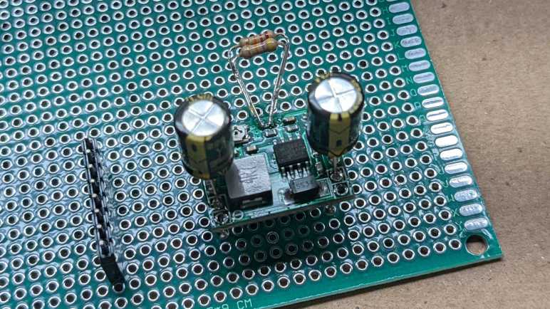
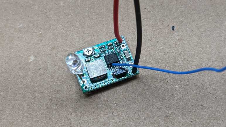
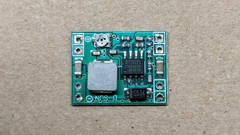
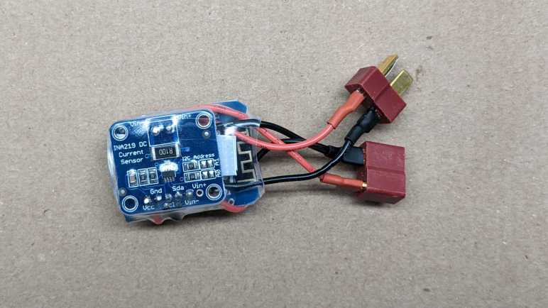
Preliminary measurements put this MP1584EN + ESP8266 + INA219 at a combined average power draw of somewhere around a quarter to a third of a Watt. This is pretty trivial in terms of home power consumption, but not if there is ambition to build nodes that run on battery power. For example, let’s do some simple math with a pair of cheap NiMH rechargeable AA batteries. With a nominal capacity of 2000 mAh and nominal voltage of 1.2V each, that multiplies out (1.2 V * 2 Amps 1 hour * 2 batteries) to 4.8 Watts over an hour. Actual behavior will vary a lot due other variables, but that simple math gives an order of magnitude. Something that constantly draws 0.3 Watt would last somewhere on the order of (4.8 / 0.3) 16 hours, or less than a day, on a pair of rechargeable AA NiMH batteries.

ESPHome has options for putting a node into deep sleep, and the simplest options are based on time like running for X seconds and sleep for Y minutes. For more sophisticated logic, a deep_sleep.enter action is exposed to enter sleep mode. There is also a deep_sleep.prevent action to keep a node awake, and the example is to keep a node awake long enough to upload a code update. This is a problem I’ve tripped over during my MicroPython adventure and it’s nice to see someone has provided a solution in this framework.

The example code reads retained value on a MQTT topic to decide whether to go to sleep or not. I think this is useful, but I also want a locally controlled method for times when MQTT broker is unreachable for any reason. I wanted to dedicate a pin on the ESP8266 for this, with an internal pull-up and an external switch to pull to ground. When the pin is low, the node will go to sleep as programmed. If the pin is high, the node stays awake. I will wire this pin to ground via a jumper so that when the jumper is removed, the node stays awake. And if the jumper is reinstalled, the node goes to sleep.

Such GPIO digital activity can be specified via ESPHome Binary Sensor:

deep_sleep:
  run_duration: 30s
  sleep_duration: 2min
  id: deep_sleep_1

binary_sensor:
  - platform: gpio
    name: "Sleep Jumper"
    id: sleep_jumper
    pin:
      number: 13
      mode:
        input: true
        pullup: true
    on_press:
      then:
        - logger.log: "Preventing deep sleep"
        - deep_sleep.prevent: deep_sleep_1
    on_release:
      then:
        - logger.log: "Entering deep sleep"
        - deep_sleep.enter:
            id: deep_sleep_1
            sleep_duration: 1min

But this is not quite good enough, because on_press only happens if the high-to-low transition happens while the node is awake. If I pull the jumper while the node is asleep, upon wake the pin state is low and my code for high-to-low transition does not run. I needed to check the binary sensor state elsewhere before the sleep timer happens. In the case of this particular project, I also used the analog pin to read battery voltage once every few seconds, so I removed the check from on_press to ADC sensor on_value. (I left on_release code in place so it will still go to sleep when jumper is reinstalled.)

sensor:
  - platform: adc
    pin: A0
    name: "Battery"
    update_interval: 5s
    on_value:
      if:
        condition:
          binary_sensor.is_on: sleep_jumper
        then:
          - logger.log: "Preventing deep sleep"
          - deep_sleep.prevent: deep_sleep_1

This performs a jumper check every time the ADC value is read. This is pretty inelegant code, linking two unrelated topics, but it works for now. It also avoids the problem of digital signal debouncing, which would cause on_press and on_release to both be called in rapid succession unless a delayed_on_off filter is specified.


Ideally, this sensor node would go to sleep immediately after successfully performing a sensor read operation. This should take less than 30 seconds, but the time is variable due to external conditions. (Starting up WiFi, connect to router, connect to Home Assistant, etc.) The naive approach is to call deep_sleep.enter in response to on_value for a sensor, but that was too early. on_value happens immediately after the value is read, before it was submitted to Home Assistant. So when I put it to sleep in on_value, Home Assistant would never receive data. I have to find some other event corresponding to “successfully uploaded value” to trigger sleep, and I haven’t found it yet. The closest so far is the Home Assistant client api.connected condition, but that falls short on two fronts. The first is that it does not differentiate between connecting to Home Assistant (useful) versus ESPHome dashboard (not useful). The second is that it doesn’t say anything about success/failure of sensor value upload. Maybe it’s possible to do something using that condition, in the meantime I wait 30 seconds.

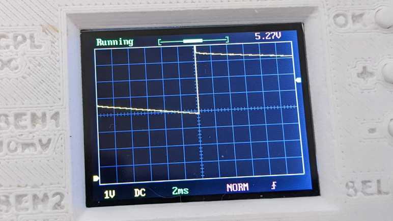
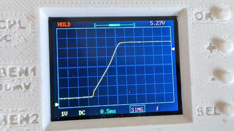
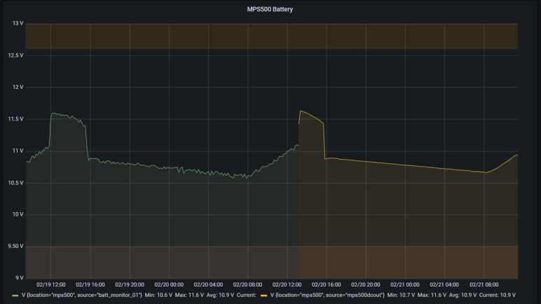
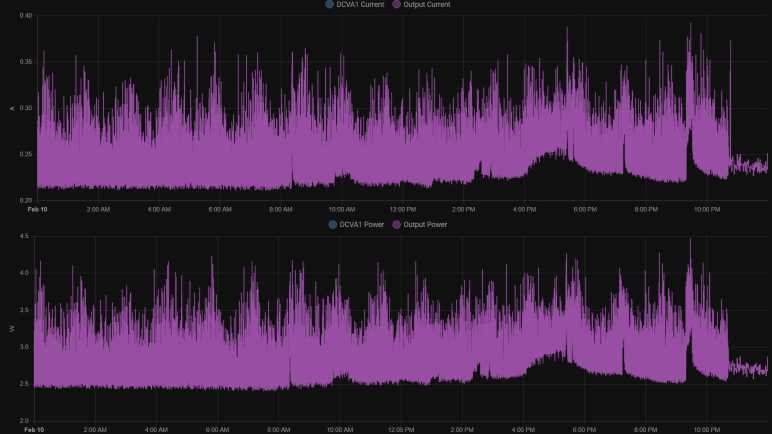
A quick search online found this person’s project also working to prolong battery life for an ESP8266 running ESPHome, and their solution is to use MQTT instead of the Home Assistant communication API. I guess they didn’t find an “after successful send” event, either. Oh well, at least I’m getting data from INA219 between sleep periods, and that data looks pretty good.

Adding Up Power in ESPHome and Home Assistant

Using an INA219 breakout board, I could continuously measure voltage and current passing through a circuit. Data is transmitted by an ESP8266 running ESPHome software and reported to Home Assistant. In order to avoid getting flooded with data, we can use ESPHome sensor filters to aggregate data points. Once we have voltage and current, multiplying them gives us power at a particular instant. The next step is to sum up all of these readings over time to calculate energy produced/consumed. We have two methods to perform this power integration: onboard the microcontroller with ESPHome, or on the Home Assistant server.

ESPHome

The Total Daily Energy component accumulates value from a specified power sensor and integrates a daily tally. (It also needs the Time component to know when midnight rolls around, in order to reset to zero.) The downside of doing this calculation on the controller is that our runny tally must be saved somewhere, or else we would start from zero every time we reset. By default, the tally is saved in flash memory every time a power reading arrives. If power readings are taken at high frequency, this could wear out flash storage very quickly. ESPHome provides two parameters to mitigate wear: we could set min_save_interval to a longer duration in order to reduce the number of writes, or we could set restore to false and skip writing entirely. The former means we lose some amount of data when we reset, the latter means we lose all the data. But your flash memory will thank you!

Home Assistant

Alternatively, we can perform this calculation on Home Assistant server with the unfortunately named integration integration. The first “integration” refers to the math, called Riemann sum integral. The second “integration” is what Home Assistant calls its modules. Hence “integration integration” (which is also very annoying to search for).

Curiously, I found no way in Home Assistant user interface to add this to my instance, I had to go and manually edit configuration.yml as per documentation. After I restarted Home Assistant, a new tally started counting up on my dashboard, but I could not do anything else with the user interface element. I just get an error “This entity does not have a unique ID“.

On the upside, doing this math on the server meant data in progress will be tracked and saved in a real database, kept on a real storage device instead of fragile flash memory. But by default it does not reset at midnight, so the number keeps ticking upwards. Doing more processing with this data is on the to-do list.


Should we do our computation on the microcontroller or on the server? There are certainly advantages to either approach, but right now I lean towards server-side because that lets us put the microcontroller to sleep.

ESPHome Sensor Filters Help Manage Flood of Data

I was happy to find that ESPHome made building a sensor node super easy. Once my hardware was soldered together, it took less than ten minutes of software work before I was looking at a flood of voltage and current values coming in from my ESP8266-based power sensor.

It was a flood of data by my decision. Sample code from ESPHome INA219 documentation set data refresh rate at once every sixty seconds. I was hungry for more so I reduced that to a single second. This allowed me to see constantly updating numbers in my Home Assistant dashboard, which is satisfying in a statistics nerd kind of way, but doing so highlighted a few problems. Home Assistant was not designed for this kind of (ab)use. When I click on a chart, it queries from SQLite and took several seconds to plot every single data point on the graph. And since there are far more points than there are pixels on screen, what I get is a crowded mess of lines.

For comparison, InfluxDB and Grafana were designed to handle larger volumes of data and gives us tools for aggregating data. Working with aggregates for analysis and visualization avoids bogging the system down. I’m not sure how to do the same in Home Assistant, or if it’s possible at all, but I do know there are data aggregation tools in ESPHome to filter data before it gets into Home Assistant. These are described in the Sensor Filters documentation. I could still take a reading every second, but I could choose to send just the average value once a minute. Or the maximum value, or the minimum value. Showing average value once a minute, my Home Assistant UI is responsive again. The graph above was for the day I invoked this once-a-minute averaging, and the effect is immediately visible roughly around 10:45PM.

The graph below was from a later day when once-a-minute average was active the entire day:

It is a cleaner graph, but it does not tell the whole story. I had used this INA219 sensor node to measure power consumption of my HP Stream 7 tablet. Measuring once a second, I could see that power use was highly variable with minimum of less than two and a half watts but spikes up to four and a half watts. When showing the average, this information was lost. The average never dropped below 2.4 or rose above 3.2. If I had been planning power capacity for a power supply, this would have been misleading about what I would need. Ideally, I would like to know the minimum and the maximum and the average over a filtered period. If I had been writing my system from scratch, I know roughly what kind of code I would write to accomplish it. Hence the downside of using somebody else’s code: it’s not obvious to me how to do the same thing within this sensor filter framework. I may have to insert my own C code using ESPHome’s Lambda mechanism, something to learn later. [UPDATE: I learned it later and here’s the lambda/template code.] In the meantime I wanted to start adding up instantaneous power figures to calculate energy over time.

Using INA219 Was Super Easy with ESPHome

Once I had ESPHome set up and running, the software side of creating a small wireless voltage and current sensor node with was super easy. I needed to copy sample code for I2C bus component, then sample code for INA219 component, and… that’s it. I started getting voltage, current, and power reports into my Home Assistant dashboard. I am impressed.

It was certainly far less work than the hardware side, which took a bit of soldering. I started with the three modules. From left to right: the INA219 DC sensor board, the MP1584EN DC voltage buck converter, and the ESP8266 in a Wemos D1 Mini form factor.

First the D1 Mini received a small jumper wire connecting D0 to RST, this gives me to option to play with deep sleep.

The MP1584EN was adjusted to output 3.3 volts, then its output was wired directly to the D1 Mini’s 3V3 pin. A small piece of plastic cut from an expired credit card separated them.

The INA219 board was then wired in a similar manner on the other side of D1 mini, with another piece of plastic separating them. For I2C wires I used a white wire for SDA and green wire for SCL lines following Adafruit precedence. Vcc connected to the 3.3V output of MP1584EN in parallel with D1 mini, and ground wires across all three boards. The voltage input for MP1584EN was tapped from Vin- pin of the INA219 board. This means the power consumed by ESP8266 would be included in INA219’s measurements.

A small segment of transparent heat shrink tube packed them all together into a very compact package.

I like the concept of packing everything tightly but I’m squeamish about my particular execution. Some of the wires were a tiny bit longer than they needed to be, and the shrink tube compressed and contorted them to fit. If I do this again, I should plan out wire my lengths for a proper fit.


Like I said earlier, the hardware took far more time than the software, which thanks to ESPHome became a trivial bit of work. I was soon staring at a flood of data, but thankfully ESPHome offers sensor filters to deal with that, too.

Notes on Running ESPHome Dashboard

Once I got Home Assistant running on my home server, I launched an ESPHome container to run alongside and pointed Home Assistant to that container via ESPHome integration. After running it for a while, here are some notes.

Initial Setup Required USB

The primary advantage of this approach is that I have an always-on dashboard for my ESPHome devices, from which I could edit and upload new firmware wirelessly. The primary downside of this approach is that I couldn’t route USB port to this docker instance, so I needed another computer to perform initial firmware flash with USB cable. There are a few options: (1) select “Manual Install” to download a binary file that I would then flash with esptool.py. Advantage: esptool is easy to install. Disadvantage: I have to remember all of the other parameters for flashing. Option (2) copy the configuration YAML file and run a separate instance of ESPHome on the computer with USB port. Advantage: ESPHome took care of all flashing parameters, no need to remember them. Disadvantage: ESPHome not as easy to install. Option (3) select “Manual Install” to download a binary, then use https://web.esphome.io/ to flash. Advantage: zero setup!

ESPHome /cache Directory

In addition to the required /config directory, we could optionally mount a /cache directory to ESPHome container instance. When present, the directory is used for items that are easily replaceable. For example downloading PlatformIO binaries and intermediate files during compilation. My /config directory is mapped to a ZFS hard drive array. It is regularly backed up so I have a history of my configuration YAML files, but it is not fast. So I mapped /cache to a SSD volume which is fast but not regularly backed up. It also gets quite large, after a few experiments I approached a gigabyte under /cache versus only a few megabytes in /config.

Not Actually Required for Home Assistant

I had thought ESPHome dashboard served as communication node for all my ESP32/ESP8266 boards to talk to Home Assistant. I was wrong! The boards actually get all the code to talk to Home Assistant directly. This meant I don’t strictly need to have Home Assistant Core and ESPHome Dashboard launch together in a common docker-compose.yml file. Home Assistant Core needs to be running, but ESPHome Dashboard could be launched just when I want to wirelessly modify a node.

Add Dashboard Password

But if ESPHome will always be left running as a standalone container, it would be a very good idea to install a minimum bar of security protection. By default, ESPHome dashboard is openly accessible, and I didn’t think it was the best idea. It left open access of all my ESPHome nodes to any port sniffers that might get on my home network. Whether I leave ESPHome running or not, I should at least add a username and password to ESPHome dashboard. This can be done by modifying the container launch commands as per parameters in ESPHome documentation.

version: '3'

services:
  esphome:
    image: esphome/esphome:latest
    command: dashboard --username [my username] --password [my password] /config
    restart: unless-stopped
    volumes:
      - [path to regularly backed-up volume]:/config
      - [path to speedy SSD that isn't backed-up]:/cache
    network_mode: host

This would not be necessary if running as an add-in with Home Assistant Operating System. When installed and managed by the supervisor, access to the ESPHome dashboard becomes part of Home Assistant user control.


All this effort to learn Home Assistant and ESPHome was kicked off when I decided not to write my own code to work with an INA219 voltage+current sensor, hoping it would be easier to use ESPHome instead. And I’m happy to report it absolutely paid off.

Hello Home Assistant

I have an existing home server set up to run Docker containers, it’s how I’ve been trying out tools like InfluxDB. I added an instance of Home Assistant Core to the list of running containers. When the first screen came up, I was happy to see that it required me to create a username and password before doing anything else. It’s the minimum bar of security, far better than leaving it openly accessible to anyone to probe a known port.

Once I got through initial setup, I was shown the “Overview” dashboard. We can create our own dashboards, but the system starts with this one. It was automatically generated, and by default it is also managed automatically to show everything that pops up. It was populated by a metrological (weather) widget, set to the home location specified during initial setup. I infer this was done so anyone starting fresh with Home Assistant has at least one item to interact with. (Of course, with the focus on local control, Home Assistant has a “Depends on Cloud” label/disclaimer/warning on such features, because it depends on weather data published online.) With weather as starting point, I could add more cards representing devices that already existed on my home network.

The TV was not the only device visible via multiple integrations. My home wireless router was made by Asus, and by default it was visible to the Universal Plug-and-Play Internet Gateway Device integration. However, I disabled that in favor of a more device-specific AsusWRT integration. The latter took a bit more work, as I had to generate a SSH keypair for secure connection between Home Assistant and the router. The public key was pasted into the router’s “Administration” control panel, in the “System” tab, under the “Service” section. I also had to enable SSH (LAN only) and I took the option to change to a nonstandard port.

Once these integrations were added, their associated entities were automatically added to the “Overview” dashboard. This was a lot of data. In fact, I think it is too much data! Thus my first lesson in using Home Assistant is going into the entities list and disabling them. For example, at the moment I don’t see a reason why I needed to know whether my TV is connected via Ethernet or wireless, so I disabled that particular entity. I appreciated the power of having all of these entities at my disposal, but this data overload is also why Home Assistant is not exactly considered beginner friendly.

Anyway, getting my feet wet with Home Assistant was fun, but ESPHome is the reason I’m here.

Notes on Home Assistant Core Docker Compose File

I’m playing with Home Assistant and I started with their Home Assistant Core Docker container image. After a week of use, I understood some of the benefits of going with their full Home Assistant Operating System. If I like Home Assistant enough to keep it around I will likely dig up one of my old computers and make it a dedicated machine. In the meantime, I will continue evaluating Home Assistant by running Home Assistant Core in a container. The documentation even gave us a docker-compose.yml file all ready to go:

version: '3'
services:
  homeassistant:
    container_name: homeassistant
    image: "ghcr.io/home-assistant/home-assistant:stable"
    volumes:
      - /PATH_TO_YOUR_CONFIG:/config
      - /etc/localtime:/etc/localtime:ro
    restart: unless-stopped
    privileged: true
    network_mode: host

This is fairly straightforward, but I had wondered about the last two lines.

    privileged: true

First question: why does it need to run in privileged mode? I couldn’t find an answer in Home Assistant documentation. And on the other end, official Docker compose specification just says:

privileged configures the service container to run with elevated privileges. Support and actual impacts are platform-specific.

So the behavior of this flag isn’t even explicitly defined! For the sake of following directions, my first launch of Home Assistant Core image specified true. Once I verified it was up and running, I took down the container and brought it back up without the flag. It seemed to work just fine.

One potential explanation: upon initial startup, Home Assistant needed to create a few directories and files in the mapped volume /config. Perhaps it needed the privileged flag to make sure it had permissions to create those files and set their ownership properly? If so, then I only needed to run with the flag for first execution. If not, then that flag may be completely unnecessary.

    network_mode: host

Second question: why does it need to run in host network mode? Unlike privileged, network mode is much better defined and host means “gives the container raw access to host’s network interface”. I tried running Home Assistant Core with and without this flag. When running without, Home Assistant could no longer automatically detect ESPHome nodes on the network. Apparently auto-discovery requires running in host network mode, and it’s a big part of the convenience of ESPHome. In order to avoid the tedium of getting, tracking, and typing in network addresses, I shall keep this line in my Docker compose file while I play with Home Assistant Core.

Notes on Home Assistant Core vs Home Assistant Operating System

Once I decided to try Home Assistant, the next decision is how to run it. Installation documentation listed many options. Since I’m in the kick-the-tires trial stage, I am not yet ready to dedicate a computer to the task (not even a Raspberry Pi) so I quickly focused on running Home Assistant inside a virtualized environment on my home server. But even then, that left me with two options: run Home Assistant Core in a Docker container, or run Home Assistant Operating System in a virtual machine.

Reading into more details, I was surprised to learn that both cases run Home Assistant Core in a Docker container. The difference is that Home Assistant Operating System also includes a “Supervisor” module that helps manage the Docker instance, doing things like automatic updates (and rollback in case of failure), making backups, and setting up additional Docker instances for Home Assistant add-ons. (ESPHome dashboard is one such addon.) If I opt out of supervisor to run Home Assistant Core on my existing Docker host, I will have to handle my own updates, backups, and add-ons.

Since I already had a backup solution for data used by Docker containers running on my server, I decided to start by running Home Assistant Core directly. After running in this fashion for a week, I’ve learned a few facts in favor of running Home Assistant Operating System on a physical computer:

  • Home Assistant Core updates very frequently, three updates in the first week of playing with it. Thanks to Docker it’s no great hardship to pull a new image and restart, but it’d be nice to have automatic rollback in case of failure.
  • When browsing the wide selection of Home Assistant integrations, there’s usually a little “Add Integration” button that held the promise to automatically set everything up for us. When the thing is an addon that requires running its own Docker container (like the ESPHome dashboard) the promise goes unfulfilled because we’d need the supervisor module for that.
  • When managed by the supervisor, addons like ESPHome can be integrated into the Home Assistant user interface. Versus opening up a separate browser tab when running in a Docker container I manage manually. This also means an addon can integrate with Home Assistant permissions so there’s no need to set up a separate username and password for access control.
  • Some addons like the ESPHome dashboard requires hardware access. In the case of ESPHome, a USB cable is required for flashing initial firmware on an ESP8266/ESP32. Further updates can be done over the network, but that first one needs a cable. Some Docker hosting environments allow routing a physical USB port to the Docker instance, but mine does not.

I could work around these problems so none of them are deal-breakers. But if I like Home Assistant enough to keep it around, I will seriously consider running it on its own physical hardware. Whether that’d be a Raspberry Pi or something else is to be determined.

In the meantime, I will continue running Home Assistant Core in a container. The documentation even gave us a docker-compose.yml file all ready to go, but I was skeptical about running it as-is.

Window Shopping Home Assistant

I learned about Home Assistant in a roundabout way, but once I started looking at it, I saw an interesting new tool I want to add to my toolbox. It started off on my good side with description on the project’s home page: “Open source home automation that puts local control and privacy first.” I like everything about that sentence and the tone it sets for the project.

I was once very interested in the promises of having a “smart home” and I was one of the early adopters of a Nest thermostat. (Before they were acquired by Google.) However, several years of Nest thermostat ownership also soured me on the concept of home automation via cloud services. Every once in a while, a server I never knew existed goes down and I get an error message on my Nest. To Nest’s credit, when their backend goes offline the thermostat continues running the last program it remembers. So it would never be worse than a “dumb” thermostat. Unfortunately not all “smart home” devices has such a graceful failure mode. For example whenever AWS us-east-1 suffers an outage, I would read about people not being able to get into their house because their Alexa-enabled smart lock wouldn’t unlock. If my smart home fails, I want it to be my own fault.

With an aversion to this class of failure, I have not bought any more Nest devices and became cool to the whole smart home concept. But maybe that will change if I could have local control and execution, and that is something Home Assistant offers. This also means any data is stored on my home server instead on somebody else’s AWS/Azure/GCP instance. It is popular for people to run on a Raspberry Pi dedicated to the purpose, but I could also run it in a Docker container on my home server as I’ve been doing for many other software pieces in this project.

While I intend to start playing with Home Assistant with DIY nodes built from ESP8266/ESP32, it offers integration with many home automation systems beyond those running ESPHome. It can even integrate with Google Nest, Amazon Alexa, and the like. But there’s a catch: to integrate with cloud-based services I would then have to either (1) open my instance of Home Assistant to the internet, or (2) use Nabu Casa’s cloud-hosted Home Assistant service.

In the near term that would not be a problem because I’m going to leave my Nest as-is. Until I’m more comfortable with the system, I’m not going to let Home Assistant control anything with drastic failure modes like locking me out of my house. I’m going to start simple and keep stakes low.

Learned About Home Assistant From ESPHome Via WLED

I thought Adafruit’s IO platform was a great service for building network-connected devices. If my current project had been something I wanted to be internet-accessible with responses built on immediate data, then that would be a great choice. However, my current intent is for something locally at home and I wanted the option to query and analyze long term data, so I started looking at Home Assistant instead.

I found out about Home Assistant in a roundabout way. The path started with a tweet from GeekMomProjects:

A cursory look at WLED’s home page told me it is a project superficially similar to Ben Hencke’s Pixelblaze: an ESP8266/ESP32-based platform for building network-connected projects that light up individually addressable LED arrays. The main difference I saw was of network control. A Pixelblaze is well suited for standalone execution, and the network interface is primarily to expose its web-based UI for programming effects. There are ways to control a Pixelblaze over the network, but they are more advanced scenarios. In contrast, WLED’s own interface for standalone effects are dominated by less sophisticated lighting schemes. For anything more sophisticated, WLED has an API for control over the network from other devices.

The Pixelblaze sensor board is a good illustration of this difference: it is consistent with Pixelblaze design to run code that reacts to its environment with the aid of a sensor board. There’s no sensor board peripheral for a WLED: if I want to build a sensor-reactive LED project using WLED, I would build something else with a sensor, and send commands over the network to control WLED lights.

So what would these other network nodes look like? Following some links led me to the ESPHome project. This is a platform for building small network-connected devices using ESP8266/ESP32 as its network gateway, with a library full of templates we can pick up and use. It looks like WLED is an advanced and specialized relative of ESPHome nodes like their adaptation of the FastLED library. I didn’t dig deeper to find exactly how closely related they are. What’s more interesting to me right now is that a lot of other popular electronics devices are available in the ESPHome template library, including the INA219 power monitor I’ve got on my workbench. All ready to go, no coding on my part required.

Using an inexpensive ESP as a small sensor input or output node, and offload processing logic somewhere else? This can work really well for my project depending on that “somewhere else.” If we’re talking about some cloud service, then we’re no better off than Adafruit IO. So I was happy to learn ESPHome is tailored to work with Home Assistant, an automation platform I could run locally.

Window Shopping: Adafruit.IO

I have an ESP8266 I wanted to use to with an INA219 chip as the voltage and current monitor for my toy solar panel array. The logged data can be visualized for curiosity, or maybe analyzed and that information fed into something in the future. I started with Arduino IDE, then moved to ESP-IDF on an ESP32, and most recently I played with MicroPython. This was a fun trip exploring the foundational elements, but looking towards the future I see a lot of software work to build this into a system and my interest started to fade.

What if somebody else has already built the infrastructure for something like this? Well, since I was on Adafruit’s INA219 page I saw that they had built one called Adafruit IO. Right up on the landing page it says: “We do the hard work so you can focus on the fun stuff.” Hey, I like the sound of that!

And in typical Adafruit fashion, they have great support for the product interoperating with a wide range of hardware. Including the ESP8266 and INA219! (Though via the Arduino platform and not their CircuitPython platform as they’ve dropped support for ESP8266 CircuitPython.) Data is logged, stored, easy dashboards for visualization, and that data feeds into programmable triggers to take action in response to date. Everything I foresaw having to build but is already here and ready to go. And the price is reasonable: free to start with limited functionality, and $10/mo to upgrade for full functionality.

This looks amazing but I decided against it, because I wanted something purely for consumption at home. I wouldn’t call myself averse to internet applications. After all, I’ve put all my code on GitHub and my project notebook is publicly readable. (You’re reading it right now.) Running some things on the internet makes sense when the intent is for access from anywhere, but for my home projects I don’t want that data to leave the house.

Also, Adafruit IO only retains data for a limited time period. From what I can see this was 30 days during the beta and the duration is something they reserve the right to change. I can’t seem to find their current data retention policy but it really doesn’t matter. Their target usage scenario is for “right now” interaction and projects like long-term historical tracking and analysis is out of scope. I want the option to store that data for longer, and to do it at home, so I passed on Adafruit IO and started looking for another solution.

Changing Project Direction to Use INA219 Power Monitor

I’ve had fun playing with MicroPython on an ESP8266, having an exception handling framework was especially welcome. I had originally intended to continue playing with MicroPython, gradually increasing the project complexity at each step, but I’ve changed my plan. The catalyst of this decision was a little breakout board for the Texas Instruments INA219 chip which measures electrical voltage (up to 26V DC), current (variable range depending on shunt resistor used), plus a built-in calculator for power (in Watts) from those two values. I bought mine off Amazon but I’ve since learned it was a knockoff of this Adafruit product so I’ll link to the original.

I had sat down with reference materials in front of me: the INA219 datasheet and the MicroPython I2C library. Then I felt a familiar sensation: that of my attention and enthusiasm fading. I know this sensation well! It stalled many projects in the past, and it is a warning sign I need to change directions fast or this project will stall as well.

I realized I was not enthusiastic about writing a MicroPython library for INA219 from scratch. There is educational value in doing so for sure, but for whatever reason right now I don’t feel the motivation I needed to reinvent this particular wheel. I went online looking for an existing solution and found a MicroPython Forum thread from someone who has done this work, pointing to their GitHub repository for the library.

Side note: Reading documentation for running this library on an ESP8266, I learned something interesting: the ESP8266 may encounter problems translating large MicroPython projects into executable code. The workaround is to use the MicroPython cross-compiler mpy-cross on my desktop and copy the resulting bytecode for execution on board the ESP8266.

If I could get this library up and running, I could see how to report resulting values to MQTT. Then I could perform calculations in Node-RED, and log calculated results into InfluxDB. Then I could start writing the infrastructure to read this data and make decisions on what to do in response. This is going to be a respectably large project and I don’t feel enthusiasm to do that, either! Apparently I’m not in the mood to learn by reinventing wheels, so I started looking to see what others have already done.