Window Shopping: NASA Perseverance Rover 3D Print Static Model

After finishing a model of Mars rover Curiosity, the obvious question is: did NASA release a 3D print static model of its successor Perseverance? And the answer is yes! Curiously, the web site page points to a 3D file suitable for graphics rendering, not for 3D printing. But poking around the GitHub repository revealed there’s a “M2020” 3D print model. (Before receiving its name, Perseverance was called Mars 2020.)

Armed with my recent experience, I looked over the files for this printable rover. First the good news: the rocker-bogie suspension is represented in much higher fidelity on this model. The full rocker bogie geometry is represented, including a differential bar that is designed for some bent paperclips to serve as critical linkages. The wheel tracks appear to be correct with the center pair of wheels having wider tracks than the front and rear pairs. And the geometry is more accurate, no weird right angle bends as concession to ease of printing.

The lack of concession to ease of printing is also the bad news. Unlike the previous model, none of the geometry has been modified to fit flat on a print bed. Printing this model will require, at a minimum, printing with supports which is always problematic. Dual-material printer with dissolvable supports should make such designs easy to print, but I don’t have one of those.

Another change from the previous model is that this one doesn’t use snap-together construction. Parts are designed to be glued together instead. It also means these files assume a much higher printing precision, since superglue requires a much tighter fit than snap-together construction.

If I saw these traits on a Thingiverse item, I would be skeptical that the model is even buildable. That site is littered with too many things that are obviously impossible, merely the dream someone created in CAD and never test printed.

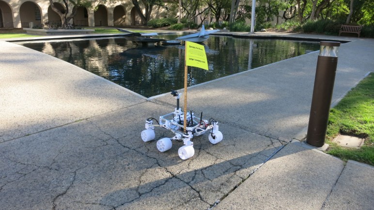
But this one appears to be real, since among the STL files is a picture of this rover design that has been built. Looking over the print quality of its parts, it was obviously printed at high detail quality on a good printer. Likely better than mine! I think I’ll hold off printing this rover design for the moment. Maybe later, when I have a well dialed-in printer that I can trust to meet precise tolerance requirements. In the meantime, I can admire the Perseverance 3D Model released by NASA that lives strictly in the digital realm.

Built NASA’s Curiosity Rover 3D Printed Static Model

I’ve completed assembly of a 3D-printed static display model, released by NASA, of Mars rover Curiosity. It had a lot of details that were demanding when printed in PETG. In hindsight, I should have printed with PLA for fewer printing problems like stringing and overhangs. It is only a display model, it’ll just sit on a shelf and not stand out in the sun as Sawppy has done (and suffered for it.) Better dimensional accuracy with cleaner printing PLA would also help make the snap-together construction more effective. PETG is more ductile and so there wasn’t a “click” to announce successful assembly.

The demanding details were fitting for a static display model. Unlike its smaller sibling, this one is even poseable with corner wheels that steer and a robot arm that can articulate through the same degrees of freedom as the robot arm of the real thing.

With its emphasis on appearance, I was disappointed at the representation of my favorite feature of NASA JPL’s Mars Rovers: their rocker-bogie suspension. The first complaint is cosmetic: this model placed all three pair of wheels with the same track (distance between left and right wheels.) Curiosity’s front and rear wheel pairs actually have a narrower track than the middle pair, which I speculated was done that way so the suspension can fold up for flight. While a static model does not need to fold up for flight, it should at least accurately represent the layout.

The next complaint is a combination of cosmetic and functional: the suspension rockers do not articulate. Their angle is fixed relative to the body. On Curiosity, the left and right rockers are connected via the differential bar which keeps the two rockers in sync with complementary movement: if one moves up, the other moves down the same amount. But on this model, the differential is a surface feature and not a functional one, without connection to the suspension rocker.

On the upside, at least this model has articulation for suspension bogies. This was also missing from its smaller sibling. With articulating bogies, this rover model can at least pretend to handle rough terrain capability even if it lacks full rocker-bogie capability. In this picture, the middle wheel is raised by a piece of 3D-printed plastic I had on hand.

And finally, the suspension arms leading up to corner steering wheels have right-angle bends that are not an accurate representation of Curiosity’s suspension. I suspect this was done as a compromise to make these parts 3D-printable without supports, but it further reduces fidelity of this model.

There are several additional print problems with this first draft. If I were excited about this model I would reprint in PLA to see if it improves as expected. But given my lack of enthusiasm about representation of rocker-bogie suspension, I am content to stop here and look around for the next project.

NASA’s Curiosity Rover Model Print Cleanup and Assembly

NASA published a 3D printable static display model for Curiosity rover, and one of the things they offered to make printing easier are STL files that have already laid out many parts so they can be printed all at once. The upside is a lot less work on setup and less time tending to the printer. The downside is that if one part fails, it dooms the entire print.

The rover suspension parts are all in a single large multipart print. The real Curiosity rover suspension structure is cylindrical, and this model tries to maintain that shape, meaning there’s very little surface area contacting the print bed at the bottom of the cylinder. In the first few failed attempts, one of the suspension parts (and never the same one twice) would pop free from the print bed and wreck havoc.

To work around this, I told MatterControl to add a brim on all parts to increase surface contact area. It allowed the print to complete, but now I have to cut all those brims off before I could proceed to assembly.

I started by cleaning up the wheel hubs and pressing them into wheels.

Following my tradition of rover building, I proceeded to build a rover wheel on a stick.

Which quickly led to a rocker-bogie assembly for one side of the rover.

Unfortunately, the rocker does not articulate on this model. Its angle relative to the body is fixed. So this particular portion of the model is no more functional than the smaller version. However, the bogie does articulate, and all four of the corner wheels can steer.

Having built one side, it was easy to build the mirror side and put everything together. I noticed I had two extra steering brackets left over. Reviewing the large multipart print, I now notice there are six steering brackets even though only four rover wheels could steer. I shrug and move on.

Assembly of the robot arm was straightforward following the directions, leaving rover head installation as the final step. The static model is complete and I can admire it in its entirety.

3D Printing NASA’s Curiosity Rover Model

I decided to build the 3D printed Curiosity rover model released by NASA, and ran into some problems with print bed adhesion. Whoever designed this model had a 3D printer with better print bed adhesion than mine. My first few printed parts would lift from my print bed.

Some of this is unavoidable, the natural orientation of some parts dictate minimal surface area. The wheels, for example, have to sit with their narrow side edges on the bed because that is the only flat side. Fortunately wheels are round and produced minimal stress.

In contrast, the body of the rover is a large rectangular solid with sharp corners. This is a recipe for lifts and they released the STL files with some pre-generated brims to help the corners stick. Unfortunately that was not enough for me, because some of the corners still lifted off the print surface. Fortunately this was only a minor cosmetic issue, since the bottom does not need to be absolutely flat to mesh with any other part.

Another cosmetic issue is the radiothermal generator at the back, which ramped up more aggressively than my Pulse XE revision D printer could handle with PETG. Fortunately this is a bottom-facing surface and shouldn’t be too much of a detraction.

The wheel spokes were the most problematic with their fine detail requiring a lot of filament retraction as the print head moves from one tiny feature to another. In my experience, retraction-heavy prints work much better in PLA than PETG, in hindsight that’s what I should have used.

An interesting nod to convenience is that, in addition to publishing STL for individual parts, the creator of this project also included STL files with many parts laid out to be printed all at once. The upside is that there’s a lot less overhead. The downside is that failures can be troublesome.

NASA’s 3D Printable Curiosity Rover

When I take Sawppy out for some publicity, people frequently ask about the 3D printable Curiosity rover static model released by NASA. Some mistakenly thought Sawppy was the NASA-released design, others wanted to know how the rovers compared. I couldn’t answer the latter because I never printed the NASA rover, to the surprise of some, so I thought I should do it at least once.

NASA’s 3D printing resources page for a printable Curiosity points to a GitHub directory that actually has two printable models. I’ve seen the smaller one at a MatterHackers event, printed by another attendee who left her little rover on Sawppy’s table to keep my rover company.

The small model has limited articulation. All six wheels can roll, but cannot steer and it could only sit on a flat surface because its rocker-bogie suspension joints are fixed. I also noticed the robot arm joint articulation doesn’t match that of the real rover’s. Still, it is undeniably a representation of Curiosity and a cute little model.

Since I’ve seen the little one, I decided to skip it and try building the larger one. “Large” is relative, of course, it would still be much smaller than Sawppy. Another important difference is that it is an unmotorized static display model, which is actually the main reason I had not tried to build it. I wanted a rover that moved!

But I’m glad I’ve built it, because it was a good study into the different compromises this model made for the sake of being 3D printing friendly.

Goodbye and Good Riddance To This Generation of Hybrid Drives

I have successfully upgraded a HP Pavilion Split X2 (13-r010dx) to use a modern M.2 SATA SSD with the help of an adapter circuit board. The results were stellar and, even though the adapter does not mount inside the computer properly, I have no plans to put the original drive back in. It was a compromised solution of its era and times have moved on.

A little over ten years ago, flash-based solid state drives started edging towards price levels affordable to normal computer buyers. A few bargain basement devices were released, and they were terrible. I had two JMF602-based drives that lasted through their 90-day warranty periods but not much beyond that. The big breakthrough in affordable and durable performance is credited to the Intel X25-M, but the capacity was quite small. SSD performance is something that I had to experience to be converted to a fan, and it was hard to get non-converts to accept living with 80GB of capacity when we had become accustomed to hundreds of gigabytes.

The compromised solution was the SSD/HDD hybrid drive: there is a magnetic platter hard disk drive, but there is also a small piece of flash memory acting as a small solid-state drive cache. The advertising proclaimed that we would get the capacity of a HDD with all the performance of a SSD. I thought the concept was enticing, but never actually got one to try.

I’m glad I did not, if this computer’s stock WD5000M21K hybrid drive is representative of the breed. Its performance was absolutely terrible. Maybe modern workloads overwhelmed its meager 8GB of flash cache. Maybe years of use has worn out the flash and there was no caching anymore. Whatever the reason, its performance was no better than a HDD, definitely nowhere near the performance of a real solid state drive.

Now solid state drives with plenty of elbow room are quite affordable, giving old computers a new lease on life. The hinderance of oddball connectors like the SFF-8784 become just a speed bump with help of adapters, so we don’t need to put up with the compromises of SSD/HDD hybrid drives anymore.

No Good SSD Adapter Mounting Option

Upgrading to a SATA SSD was a hugely successful transformational upgrade for this old HP Pavilion Split X2 (13-r010dx). Physically, it was only a tiny improvement to the problems of heavy weight and it doesn’t nothing to help the low 1366×768 resolution screen, but the computer is now immediately responsive to user input and no longer miserable to use. That is the good news.

The bad news is that Sintech’s SSD adapter didn’t have mounting holes to line up to original mounting brackets. I originally thought I could 3D-print something to adapt its vertical mounting holes to horizonal, a simple rectangular loop should do the trick. Then I took a closer look at the dimensions and realized it’s not so simple.

The circuit board height where the interface plugs into is fixed and that height is in the middle of the screw holes. In order to clear mounting screws I would have to cut into the circuit board, which I’m not prepared to do. I already had to wait for a replacement to be shipped to me once, I didn’t want to ruin a board and have to wait again.

I considered offsetting vertically to clear the screw holes, moving in one direction or the other. But the overall height of this adapter + M.2 socket is barely any thinner than the original hard drive, leaving very little margin to work with. Pushing towards the screen, I could not move far enough to clear the screws. Pushing towards the back, clearing the screws would bump against the back cover.

So no 3D-printed adapter bracket for me. I ended up using double-side tape sold for attaching Raspberry Pi heat sinks, and used that to attach the SSD to the chassis. This solution is not ideal, but I’m not willing to revert to the stock hard drive because it was something better left to the past where it belongs.

HP Split X2 (13-r010dx) Transformed with SSD Upgrade

With a SSD adapter circuit board temporarily held in place with painter’s tape, I powered up this old HP Split X2 (13-r010dx) to see if it’s willing to run on a modern M.2 SSD. The answer is yes — and quite well!

I have a USB flash drive prepared by the Windows Media Creation Tool for installing Windows 10 2004, and I could select it as the boot device by holding down F9 upon power-up. From there it was an uneventful Windows 10 installation, automatically activated by a Windows 8 license embedded in hardware.

Here is the “Before” picture, taken a few minutes after the computer has booted up on the original WD5000M21K hard drive. The computer is completely saturated with Windows startup tasks and it takes a few minutes to even get Task Manager up and running and a screenshot tool. From here we can see we’re doing well on memory, with only half used. The CPU is largely idle. They are all waiting for the disk.

Here is the “After” picture, taken shortly after the computer started up for the first time running Windows 10 freshly installed on the M.2 SSD. Disk overhead has stopped being a constraining factor. The memory is about the same, and now the humble low power Core i3 CPU is the constraining factor as this computer is chewing through information to decide what to download from Windows Update.

Once Windows was up to date, all drivers were automatically installed, and this computer was ready to go. A reboot verified that startup time has gone from several minutes down to less than 30 seconds. Launching and switching between applications are nearly instantaneous. When the meager 4GB RAM starts running low, virtual memory on the SSD is perfectly usable and not the molasses slow torture session it used to be.

The Core i3 might be the low end of the Core line, but it is far faster than an Atom chip of similar vintage. Freed from the shackles of its molasses slow stock HDD, this computer is now perfectly comfortable running up-to-date Windows 10 and modern applications. This SSD upgrade has proven to be a hugely beneficial transformation for this old computer. Which was fantastic! Except for one problem… how do I make sure it doesn’t rattle around inside the machine?

HP Split X2 (13-r010dx) SSD Upgrade: Round 2

I now have a M.2 SATA SSD available for experimentation, mounted on a Sintech ST-NG8784 adapter circuit board that lets me plug a M.2 SSD into a SSF-8784 connector. This unusual slim connector is used by a HP Pavilion Split X2 (13-r010dx) tablet/laptop convertible computer, which foiled an earlier attempt at SSD upgrade. This time I am better prepared.

Here’s the “Before” picture, with the stock SFF-8784 hard drive in the center. From the factory the interior of this device had a lot more tape and foil, including foil completely wrapping the hard drive. They’ve all been pulled off in earlier adventures.

In addition to disconnecting the AC adapter, the connector at the center of the image (with black wires, not white ribbon cable) is for the battery and should be disconnected before working on this machine.

Four screws held the drive in place using some metal brackets, which were in turn mounted to the drive via some screws on the side. Removing them were trivial, but that exposed the next problem: the PCB could match bottom mounting holes, but we need horizontal ones, so there’s no good way to fasten the drive.

I decided not to worry about proper fastening for the moment, because I had no idea if the computer would even accept this drive with adapter. Some temporary painter’s tape is enough to make sure the board doesn’t flop around while I experiment.

Examining Sintech M.2 to SFF-8784 SATA Adapter (ST-NG8784)

It took a second try before I received an adapter card that looked good enough to proceed. The objective of the exercise is to put a common M.2 2280 SATA SSD into an old HP Pavilion Split X2 (13-r010dx) convertible laptop which came with an unusually thin (5mm) spinning platter hard drive in the super rare SFF-8784 form factor. The form factor foiled my first attempt at an SSD upgrade for this computer, but now I have a M.2 SATA SSD available for experimentation and now I have the adapter card I bought (*) for the project.

This card is made and sold by Sintech, which has a product page for this item where I learned it is designated model ST-NG8784. I was fascinated by how simple the adapter is. There are only a few surface mount components and very few traces on the circuit board. C1 and C2 are obviously capacitors, but I’m not sure what U1 is. Searching on “84-33 2012DC” didn’t result in anything enlightening, but by its general shape and arrangement of nearby capacitors I guess it is a voltage regulator.

The M.2 connector has many, many pins but the SFF-8784 plug has significantly fewer, resulting in a superficially simple layout. I guess that makes sense, after all the S in SATA stands for Serial, so it wouldn’t need many pins to do its thing. I count just two differential pairs on top for data. Most of the other connections are either power or ground. But it does highlight the fact there is no active signal conversion on this adapter: this would only work for SATA M.2 SSDs and I would not expect it to work with NVMe M.2 SSDS.

Mechanically, this adapter card has provisions for several of the popular M.2 card lengths. A threaded standoff has been press-fit into the spot corresponding to the longest supported size M.2 2280. If the user has a SATA SSD in one of the shorter form factors, there is a small Ziploc bag with a screw-on standoff to be installed in the appropriate slot. Since my M.2 SATA SSD is in the 2280 format, I did not need the Ziploc bag. I installed my SSD into this adapter and turned attention to the laptop.


(*) Disclosure: As an Amazon Associate I earn from qualifying purchases.

SSD Upgrade Project Delayed By Shipping Damage

I’ve been aware that the performance of an old HP Pavilion Split X2 (13-r010dx) is constrained by its hard drive to some degree. But when I tried to remove that constraint by upgrading it to a commodity SATA SSD, I found that it did not use the connector type I was familiar with. Rather, it used a much thinner and rarer variant called SFF-8784. Native SFF-8784 drives are expensive due to their low volume, but I found an Amazon vendor selling SFF-8784 adapter circuit boards to use mSATA or M.2 SATA SSDs. I resolved to come back to this project later, when I have a spare M.2 SATA SSD to try.

It is now later. Thanks to some end-of-year sales, my computers received upgrades and the cascade of hand-me-down freed up a M.2 SATA SSD for this experiment. I proceeded to order the M.2 to SFF-8784 adapter board I found earlier (*) eager to see how it might improve the old HP’s responsiveness.

Unfortunately, the first adapter arrived damaged. It was shipped in an anti-static bag and enclosed in a padded envelope. The padding was apparently not enough, because the M.2 connector was crushed out of shape. I doubted it would accept a M.2 SATA SSD and I didn’t want to risk a perfectly functioning SSD to try.

I contacted Sintech and they sent a replacement. When the replacement arrived, I noticed a modification. It was still in an anti-static bag in a padded envelope, but there was the additional padding of a block of pink foam to protect the M.2 connector.

With the help of this pink foam block, the onboard M.2 connector survived shipping and looked good enough for this SSD upgrade project to begin.


(*) Disclosure: As an Amazon Associate I earn from qualifying purchases.

I Started Learning Jamstack Without Realizing It

My recent forays into learning about static-site generators, and the earlier foray into Angular framework for single-page applications, had a clearly observable influence on my web search results. Especially visible are changes in the “relevant to your interests” sidebars. “Jamstack” specifically started popping up more and more frequently as a suggestion.

Web frameworks have been evolving very rapidly. This is both a blessing when bug fixes and new features are added at a breakneck pace, and a curse because knowledge is quickly outdated. There are so many web stacks I can’t even begin to track of what’s what. With Hugo and Angular on my “devise a project for practice” list I had no interest in adding yet another concept to my to-do list.

But with the increasing frequency of Jamstack being pushed on my search results list, it was a matter of time before an unintentional click took me to Jamstack.org. I read the title claim in the time it took for me to move my mouse cursor towards the “Back” button on my browser.

The modern way to build [websites & apps] that delivers better performance

Yes, of course, they would all say that. No framework would advertise they are the old way, or that they deliver worse performance. So none of the claim is the least bit interesting, but before I clicked “Back” I noticed something else: the list of logos scrolling by included Angular, Hugo, and Netlify. All things that I have indeed recently looked at. What’s going on?

So instead of clicking “Back”, I continued reading and learned proponents of Jamstack are not promoting a specific software tool like I had ignorantly assumed. They are actually proponents of an approach to building web applications. JAM stands for (J)avaScript, web (A)PIs, and (M)arkup. Tools like Hugo and Angular (and others on that scrolling list) are all under that umbrella. An application developer might have to choose between Angular and its peers like React and Vue, but no matter the decision, the result is still JAM.

Thanks to my click mistake, I now know I’ve started my journey down the path of Jamstack philosophy without even realizing it. Now I have another keyword I can use in my future queries.

Sawppy Documentation: Change Preview and Other Notes

I am optimistic that one of the popular static site generators can help me reach my goals for an improved Sawppy documentation site. But the site generator itself is not enough, there are a few other details I’ll have to investigate. The primary one being ability to preview changes to pages earlier rather than later in the pipeline.

Today’s flow of editing markdown files can deliver immediate feedback because GitHub has a “Preview” tab on its built in Markdown editor. But once we’re no longer directly using GitHub’s simple Markdown transformation, we’ll lose that ability. Contributors should not be expected to set up a SSG environment on their computer in order to see the results of their work, and asking maintainers to review every change on their own SSG environment would not scale. (I say this using plural as if Sawppy has a big maintenance staff… it’s actually just me.)

The answer is to bring in tools from the continuous integration world, where tools exist to preview changes to a website before deploying live. Some use services like Netlify, which is not itself open source but there is a free tier available.

One example: look at the repository for Write the Docs website. Open one of the pending pull requests and click on “Show all checks”. One of them is “Read the Docs build succeeded!” and clicking “Details” will bring up a version of the site built with changes in the pull request. This is an interesting venue of investigation to learn more about.

This was the point where I ran out of steam, and the Write the Docs meeting ran out of time, but I have a big treasure trove of pointers to investigate and keep me busy for a while.

Other miscellaneous notes:

Sawppy Documentation Suggestion: Static Site Generators

I’m glad I had the chance to learn about terminology and tools of industrial-strength documentation. They are great for their respective niches, but adopting any of them would require major changes and I’m not ready to take such a big leap just yet. Which brings us to static site generators. (SSG) This category of software tools see a lot of open source development, giving us many options to choose from.

Background: As input, SSGs take content in various formats. A set of rules and templates are applied to that content, generating as output a set of HTML and CSS (and maybe JavaScript) files that can be served by any web server. “Static” in this context means the web server does not have to run any code to modify the files, they are transmitted directly to users’ web browsers as-is. (As opposed to a dynamic systems like PHP.)

A large number of SSGs accept Markdown as a text content input format, so Sawppy’s existing Markdown documentation could be used with small modifications rather than complete rewrites. This also preserves the advantages of using Markdown, meeting the ease-of-use challenges A and B.

Every SSG offers customization of the rules and templates that it applies to content. At the minimum there are themes for cosmetic appearance, but plugins and extensions allow more extensive functionality. This is where I hope to create something that meets my challenge C including a lightweight BOM tool. Around this point Eric spoke up that the JPL Open Source Rover documentation system has a script that generates parts list from document content, but the generated dependency tree is not exposed to the viewer. I want to build upon that precedent and also make this kind of information available to rover builders.

To be pedantic, Sawppy documentation is already using a SSG because GitHub does not display raw Markdown files. A simple transformation to HTML has been applied for display. However, the reason I started this investigation is because the simple GitHub transformation is very limited. GitHub is aware of this, and as an upgrade, has built-in support for a SSG called Jekyll for generating GitHub Pages.

As another example, most of us had experience reading technical software documentation on some subdomain of ReadTheDocs. All of these content were generated by a SSG. MkDocs and Sphinx are two popular SSGs for ReadTheDocs, and a lot of the default functionality (automatic indexing, references, etc.) useful for technical software documentation would be useful for Sawppy as well.

But features like a lightweight BOM tool would be outside the scope of software documentation, so there were several recommendations for investigating Hugo. It is apparently the current darling for flexibly transforming content (including Markdown text) into varying different presentations. Associated with Hugo is Docsy, a Hugo theme focused on technical documentation.

Hugo and Docsy would be a bigger step up in complexity than something like Jekyll, but I’m optimistic that the benefit will justify the cost. I plan to use that as my starting point and expand my experimentation from there. But they’ll only be a part of the solution, because no matter the static generator I use I will still want a way to preview changes.

Sawppy Documentation Suggestion: BOM and UML

I had the dream of a documentation system for Sawppy that doesn’t seem to fit anything out-of-the-box, but I had the chance to ask a group of documentation experts for what they thought might apply. It looks like DITA is the super flexible Swiss army knife for documentation. It is a free open standard, but the only freely available DITA software tool I could find works at a low level and I would have to put in a lot of time to build up the system I dream of. In addition, some of the problems I wanted to solve edge into other well-established problem areas.

Bill of Materials

Similar to documentation, the challenge of tracking parts and components is well-tread ground for engineering projects. People at the meeting with industry experience suggested a few terms. MRP or Materials Resource & Planning was one, plus several variants on BOM or Bill of Materials. This area is big business! Sadly free open source tools are scarce. Someone gave a pointer to OpenBOM.com but upon further research I was disappointed to find that despite the name, this tool is not actually open.

That leaves us with few choices between “use a spreadsheet” and big ticket enterprise software. Even if numerous choices were available, such tools are focused on a very small subset of the overall problem. I do want to set up some kind of parts management, but bringing in a full fledged BOM tool adds a lot of complexity I’m not sure is justified for a small scale project like Sawppy.

Model All The Things

I had the same concern about another series of suggestions: fully model everything about Sawppy using a modeling language like SysML or PlantUML. I agree doing so will result in a complete picture, breaking down every part of the rover project. Such data could then feed into software packages that generate visualizations plotting dependencies between components. That sounds good, but the amount of work also felt disproportionate to the benefit it would bring to a project of this scale.


What I hoped would be a better fit for a project of Sawppy’s scale are the documentation systems already available for open-source software projects. While they would not have some of the hardware-focused features — such as BOM or UML above — they are more approachable than DITA and promise to be amenable to customizations. Perhaps even to give a lightweight subset of big BOM and UML tools.

Sawppy Documentation Suggestion: DITA

I outlined my Sawppy project and the challenges I want to tackle to the combined Write the Docs LA/SGVLUG meetup on the evening of October 8th. Sawppy’s current system of a loose set of Markdown files score highly on ease of contribution (challenge A) and ease of management (challenge B), but fall flat on querying dependencies (challenge C). What can I look into that helps improve information presentation without giving up the rest?

Fundamentally speaking, challenge C is not new, as it would be desirable in any large scale engineering project. The novel twist here is the desire to do it all with a system that is inviting for public contribution. As a general rule, documentarians for large engineering projects are professionals who have undergone training and have licenses for proprietary software tools.

DITA

Most such tools are excluded from consideration due to cost, but many of them deal with DITA, an open XML-based data model for authoring and publishing under the custody of the OASIS consortium. It is the standard answer to reassure customers wary of being locked in to proprietary file formats. And since it is an open format, there exists a DITA Open Toolkit to transform DITA data to desired output formats… HTML, PDF, even Markdown! There are learning resources at https://learningdita.com/

As a XML (and thus text) based format, DITA would be GitHub friendly for branching and merging. It is very flexible for creating any organization we want (creating a “Subject Schema” for DITA) but taking advantage of that power will take work. DITA Open Toolkit functions at a lower level relative to the other tools discussed later. A quick web search found many commercial offerings built on DITA (example: https://easydita.com/) but failed to find free open source counterpart.

So DITA is powerful, but that power comes at a cost, and I’ll have to decide if the cost/benefit analysis comes out in favor. This also applies to several other professional documentation concepts.

Sawppy Documentation System Challenges

I want to improve the usability of Sawppy documentation. Keeping in mind some example problems I want solved I started my quest. To find a system to document and track these types of relationships, without losing too much of the advantages of my current system. This means every candidate system must meet the following challenges:

Challenge A: Easy to Contribute

When a Markdown file is hosted on GitHub, a potential contributor can click the “Edit” button to create a fork of the repository, make a quick fix, and create a pull request all via GitHub website. This presents an extremely low barrier to entry for contributors which is a feature I want to preserve. If contributors were required to install and learn some piece of documentation software, that would discourage many people from participating before we even talk about the learning curve for that software.

Challenge B: Easy to Manage

When using GitHub’s web interface to edit a Markdown file, visualizing the change is as simple as clicking over to the “Preview” tab of the editor. Sadly such ease can’t be matched by any system external to GitHub, but it would be nice to have some way to let a contributor see what the end results look like. Failing that, I must have a way to visualize the final impact of changes before I merge a pull request. It is unacceptable to not see changes until after merging into the main branch.

Challenge C: Easy to Query

The desired documentation system will take metadata written by document author and build an interactive presentation. This way rover builders can find information without being constrained by the current linear narrative. Here are some examples of questions I’ve received for Sawppy, rephrased in terms of wheel axle.

  • (Easy: positive query) I’m on the wheel hub assembly page, and it needs the wheel axle which I guess I forgot to build. Where do I need to go?
  • (Hard: negative query) My order of 8mm shafts got delayed. What can I work on now that’s not dependent on having these shafts?
  • (Both of above) How can a teacher most effectively divide up rover tasks so multiple students teams can build the rover in parallel?

Challenge D: Free

It would be nice for the system to be free as in freedom, but at the very least it must be free as in beer. Design for Sawppy is given away at no cost to rover fans everywhere, there is no profit to cover monetary expense of a commercial documentation system.

Once I laid out these challenges to the group and opened the meeting to discussion, people started offering suggestions. Some professional documentarians brought up DITA as a venue for investigation.

Sawppy Documentation Shortcoming Example: Wheel Axles

To illustrate problems with Sawppy’s documentation, I’ll use a single component as example: Sawppy wheel axle. There are at least three entirely separate pages relating to the wheel axle:

  1. The page of parts list, telling a builder to buy 8mm metal shaft.
  2. The page for 8mm shaft modification, where I describe how to cut the long shaft into shorter segments. Followed by steps to turn these segments into wheel axles. Other segments were turned into steering shafts, plus those turned into rocker-bogie suspension pivots.
  3. The page for wheel hub assembly, which incorporates a single segment of the 8mm wheel axle shaft.

While these three files were all linked from the index page, there’s no obvious way to retrieve the relationship between them in the context of wheel axles. I can manually add links between them, but this is time consuming and perpetually incomplete. Even worse, as the number of relationships grew, it will quickly become a maintenance nightmare.

Thus I started my quest to find a system to document and track these types of relationships without losing (too much) of the advantages of my current system.

Sawppy Documentation Could Be Better

When I decided to release Sawppy to the world, I thought briefly about how to best organize all the information I want to convey for rover assembly. I quickly fell into a state of Analysis Paralysis and, as a path out of that state, decided that it was better to have something written down whatever the format. No matter how unorganized, is still better than keeping it all in my head.

I first tried putting it in the “Build Instructions” section of Sawppy’s Hackaday.io page, but that feature has some strange and unpredictable limitations that became annoying as the length of instructions grew. The final straw was when I noticed that images and instructions for earlier steps were disappearing as I added later steps. That made me… unhappy, so I went to something else.

The second attempt is what I have as of today: a loose collection of Markdown files on a Github repository. Edited in a code editor rather than a word processor, I struggled with typos and grammatical errors as I lacked the usual automated proofreading tools present in a word processor. Still, with a large helping of assembly pictures, it was just barely enough to help other people build their own rovers.

I was painfully aware of the fact there is a ton of obvious room for improvement. This was just the “get it written down” first stage and at some point I need to revisit the various problems still open. The most significant of which is lack of structure beyond an index page with links to all the other pages. The index suggested a relative ordering that matched my personal assembly order, but that doesn’t necessarily work for anyone else. And worse, they would be stuck if they wanted to ask some specific questions my layout is unable to answer.

Cardboard Absurdity: Sexy Minion

I abandoned the first draft of my cardboard Mike Wazowski for another attempt later, but I did not abandon my other Hallowing. An idea to put it to use came courtesy of Emily’s reply to my cardboard minion tweet.

This “sexy minion” is certainly not something I would have found on my own, and my initial reaction was probably what Emily intended: vaguely disturbed and resignation to the fact I can’t un-see that image.

But it’s on Twitter now, and it’s also in my brain now, and I do have an extra Hallowing on hand, so I decided to play along with the joke with a minimum-effort project. I imported the image into a photo editor and scaled it so the eye is the right size to use with a Hallowing. Fortunately it fit on a sheet of standard letter-sized paper so I didn’t have to crop any part of it off.

I tried to print it on my color inkjet printer, but that thing hasn’t printed anything in months (possibly years) so naturally its print nozzles were clogged. A standard unclog routine did not fix it and I didn’t want to spend time troubleshooting. (Remember: minimal effort.) So I printed on my monochrome laser printer and colored it in manually afterwards using markers.

Given the minimal effort I didn’t try to trace the outline curves with my new favorite cardboard tool the Canary knife, just a rectangular piece of cardboard and the marker-colorized paper taped on top. My X-Acto blade made quick work of the eyehole, and the second Hallowing was taped in place. I set it up my convertible photo studio for a quick video and threw it up on Twitter.

This silly little project couldn’t have taken more than half an hour (even less if I subtract fussing with the clogged inkjet) and it turned out to be unexpectedly (or is that disturbingly?) popular. As a result I have the sinking feeling this is not the last I’ve seen of “sexy minion”.

I also felt a bit bad that I didn’t put in the time to research where that drawing came from. It wasn’t a big deal when I thought it’d just be a throwaway joke between friends, but with thousands of views the artist’s name should have been attached. I can’t edit my original tweet, but I could at least credit the artist @nicoisesalade here: