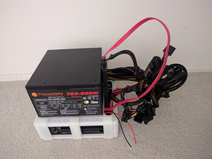
The previous two posts discussed the design reasoning behind the positioning for the power supply unit and the motherboard. Now we get to the most interesting problem: Where do we want to position the screen?
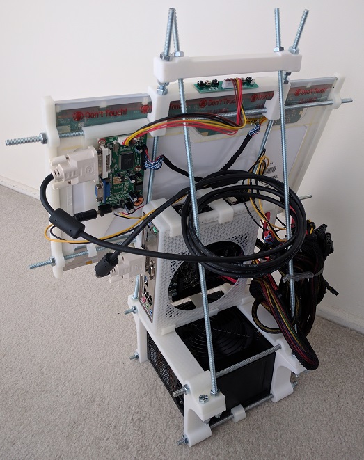
The easiest approach is to line the screen up with the existing components, so I tried that first. A 17″ screen is almost the same length and width as the ATX motherboard plus PSU. But that means the screen would be at a vertical (portrait) orientation. While common for phones and tablets, it is not a typical layout for a desktop PC. (Historical trivia: The Alto by XEROX PARC, recognized to be one of the first computers with a graphical user interface, uses a portrait orientation.)
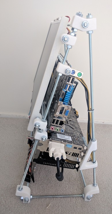
 The easiest solution to that problem is to rotate the whole works 90 degrees. I tried it for a while and the upright screen sitting at table height level was ergonomically poor.
Laptops also have their screens at table height (one of my peeves against laptops) but at least their screens can tilt. I wanted to do even better than merely tilting: I aim for the OSHA ergonomic recommendation raising the top of the screen to eye height.
 The wasted volume between the screen and the motherboard was another problem exposed by this prototype. The space looked small in CAD because the CAD model blocked out all the volume allocated by ATX spec. Since the actual motherboard consumed only a fraction of the allocated volume, the real world example had far more wasted space.
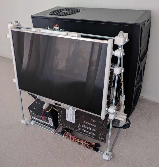
 I had the idea to solve both issues by raising the screen high to eye level, oriented horizontally, and tilt it into the empty volume. I never got as far as building it. Looking at the CAD layout, it is quite clear that the horizontally-oriented screen sticks out on either side of the case. This makes for a shape awkward to transport and also leaves the screen extremely vulnerable to damage. The screen height was good, but everything else was bad.
Plus, there was one more problem not addressed by any of these ideas: The screen glass surface is exposed while in transit. Laptops fold closed to protect the glass while travelling, but all these designs leave the glass exposed.
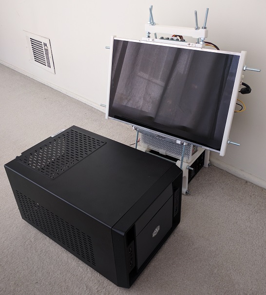
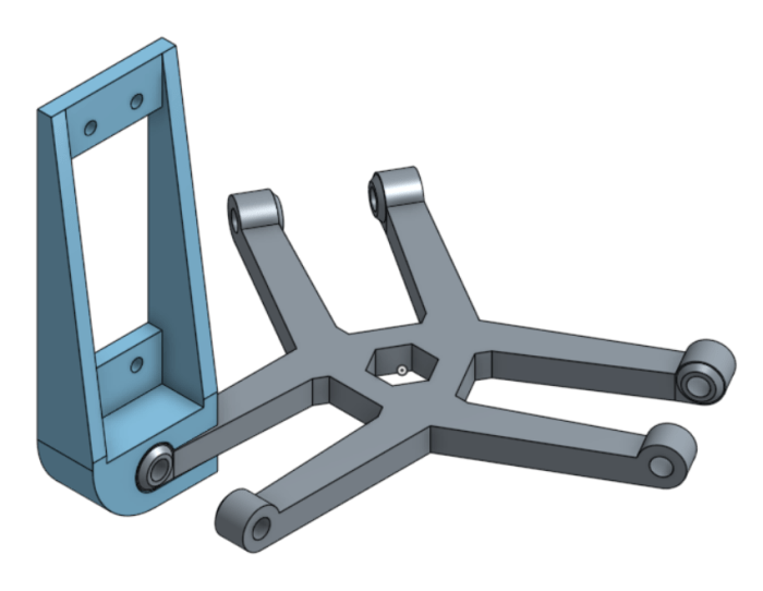
It became clear that no single static arrangement will have all of the desired qualities. Similar to a laptop, we will need some kind of mechanism to switch between two states.
- Closed: A compact configuration for easy transport while protecting the screen from damage.
- Open: An ergonomically desirable screen position.
Next post: The mechanism to address these challenges.

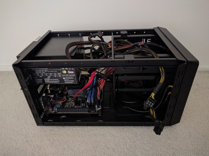
 The GPU itself is the next challenge. The primary slot is close to the CPU, which means it is going to stick up in the middle of the board, making the whole assembly awkward to fit. Again, I have an escape if I want it: there are PCIe extension ribbons available for purchase that allows more positioning flexibility for the GPU. They range from $89
  The GPU in the middle of the board leaves two rectangular volumes on either side: Both volume are candidates for use. One volume sits over the remaining expansion slots, and the other volume sits over the CPU.
 The latest iteration of the home built luggable computer gets a fancy rotating screen to protect the screen while in transit and hold the screen up while in use.
 I’ve known about Hackaday for a while, both the professionally curated site
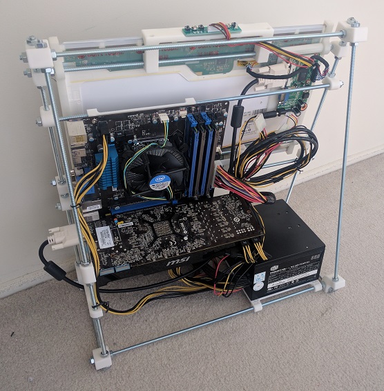
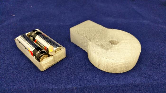
 And now another entry in the “3D printer is not the solution to everything” file.
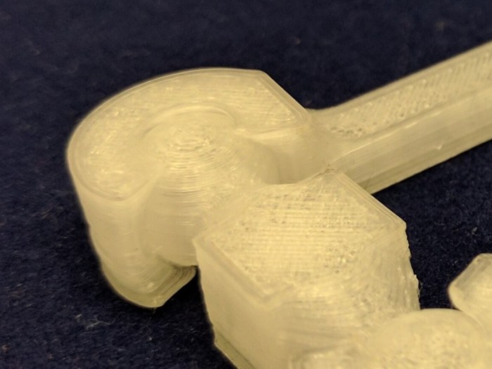
 I had been using
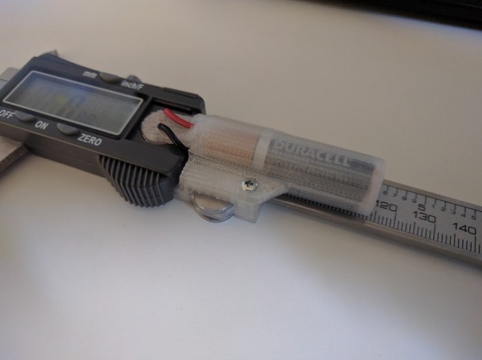
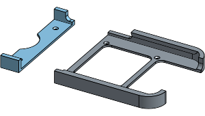
 And now, a story of failure not the fault of the 3D printer. The previous project allowed my Nexus 5X phone to sit correctly in the Utopia 360 VR viewer. This project addresses the next problem: the need to tap the screen during use of the VR app.

 Earlier this week Google officially released details about their upcoming
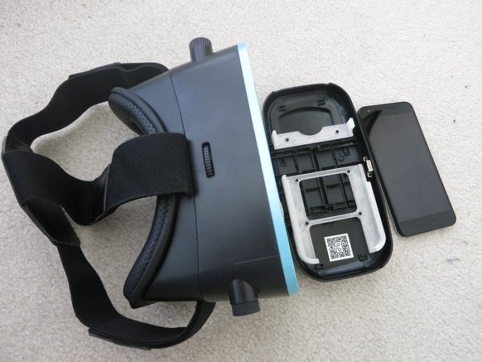
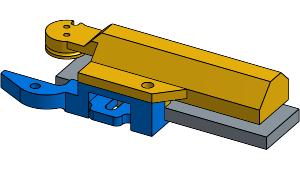
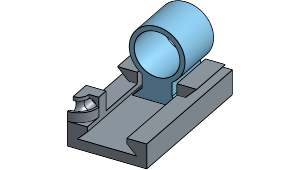
 I’ve enjoyed using my 3D printer to solve little problems around the house. This project was extra amusing: I wanted to solve a problem I had with my 3D printer that I wanted to solve with the 3D printer.
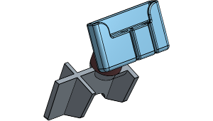 Given how popular it is to have mapping and navigation on the phone, there are a lot of phone mount products on the market. Unfortunately, given the diversity of phones and of cars, it isn’t feasible for product manufacturers to custom make individual design for every car + phone combination, so every mount is a generalized trade-off of some sort.
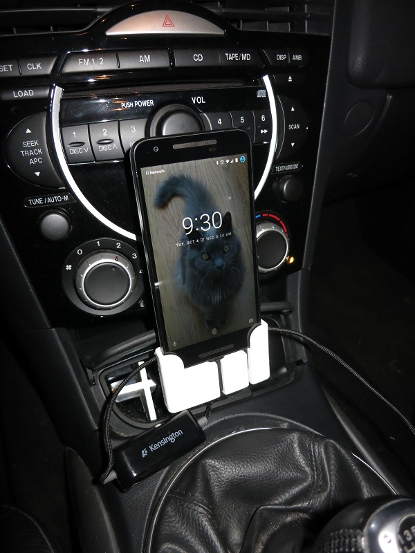
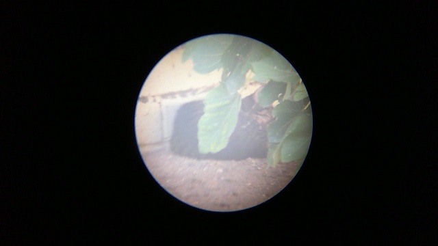
 Spotting scopes sold for bird watchers and rifle marksmen can be quite inexpensive compared to serious camera lenses of similar zoom capability. I knew there was a difference in the picture quality but wanted to try it first hand.
 Nowadays people are familiar with recycling. But some people forget recycling is only the third alternative in “reduce, reuse, recycle.” The goal of this project is to reuse small glass jars instead of tossing them into glass recycle.
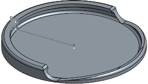
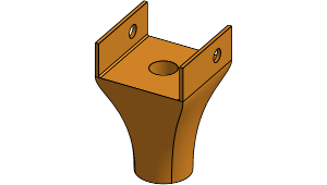 All modern garage door openers have a safety feature: a small light beam to detect objects that might be in the way. Most of the time this feature is unobtrusive working in the background for my safety.
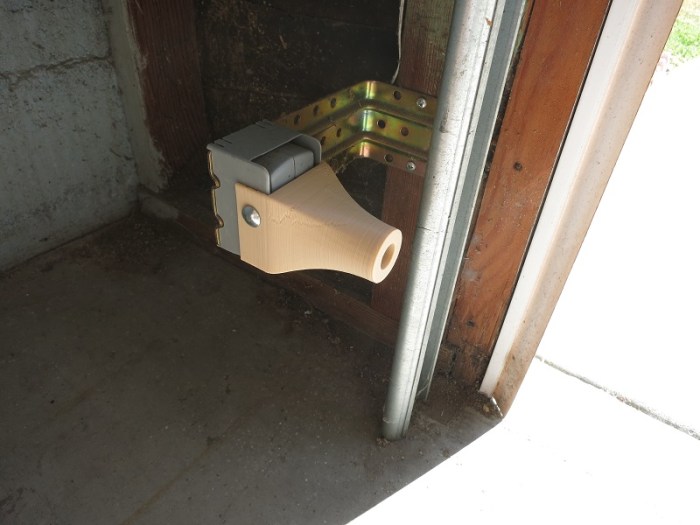
 The “Duck light” project earlier was a lot of fun, crafting an object to be lit with a little LED tea light. I liked the result so much I kept it lit around the clock, which led to the obvious next problem: battery life.