Old Drill Press Is New Drill Press

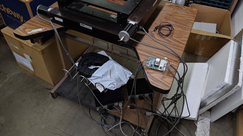
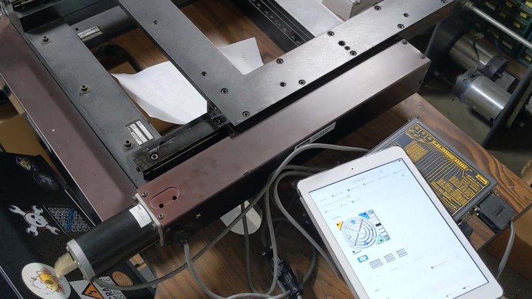
When local fellow maker Emily upgraded to a big floor standing Delta drill press, her old benchtop drill press was up for grabs. “Free if you pick it up” were the terms of the sale, and I was glad I could pick it up before someone else did. Taking part in countless Emily projects in the past, it shall now play a role in my projects in the near future.

Its long history in the hands of many handy creators showed clearly, with many stock parts missing replaced by either scratch fabricated or adapted parts. This is not a problem at all, a drill press is fundamentally a fairly simple machine and none of the modifications changed its ability to do its core job. Besides, with a less-than-new machine, I feel less intimidated about adding my own modifications as necessary.

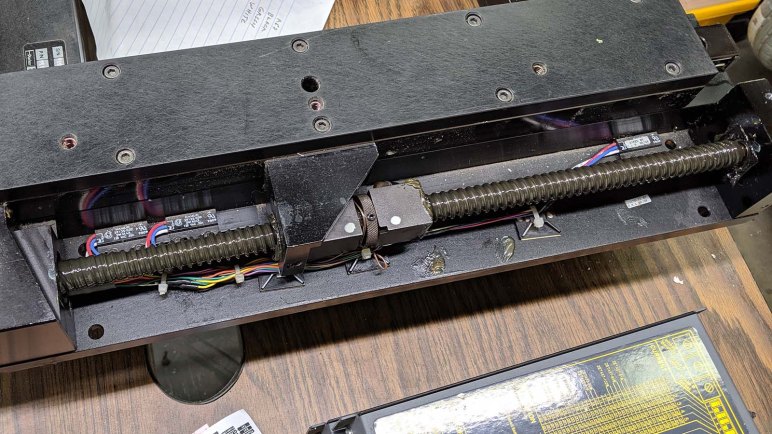
The first project on the list addressed a known existing mechanical problem: the drive belt occasionally rubs against the chassis when it is installed in the lowest and slowest of four pulley slots. I inherited a workaround from Emily which I was content to leave in place, but then I saw the set screws holding the pulley to the motor shaft.

Drill press motor pulley

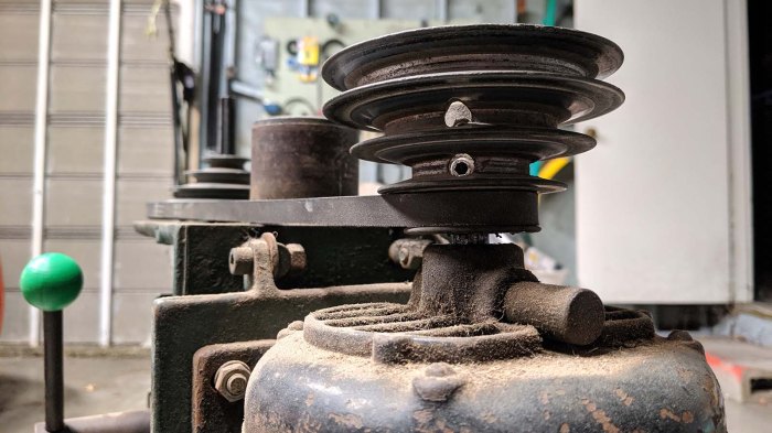
I thought it might be worth a shot to try loosening the set screw and move the pulley a little higher. There might be a good reason why the pulley was in its location. I thought it was possible (likely) the motor was not original and had a shorter shaft, or something along those lines. But it was worth investigating.

I put my hex wrench on the set screw and discovered it is loose now. The reason this pulley is too low is because the set screw came loose and it fell down due to gravity. I moved the pulley a little bit higher, tightened the set screw, and we’re back in business without any rubbing between belt and chassis. This was a great start to what I hope will be a long illustrious career for this drill press, enabling my project ideas in the future.

Industrial Glass Marbles

I remember playing with glass marbles as a child’s toy. I also remember mom being not terribly pleased when she would find them in various corners of the house, and definitely unhappy when some were on the floor where an adult might step on one and fall.

I also remember the swirls of color that were added to the glass to make them look prettier, and those are absent from industrial glass marbles. They have a job to do, and they don’t need to look pretty doing it. Not only do they lack the colorful swirl, they don’t even necessarily need to be perfectly spherical or have smooth exterior surfaces. I hadn’t known about these glass marbles with jobs until I learned of an overturned truck accident that was very difficult to clean up because its cargo were a full load of industrial marbles.

Curious, I read up on industrial glass marbles and how they are employed. I was excited when I learned that they are commonly used inside aerosol spray cans to stir its contents. They are what rattles when we shake up a can before spraying. I consumed several spray cans of Plasti-Dip for my RX-BB-8 project and saved the cans planning to cut into them to look at some industrial marbles up close. I finally got around to that particular project.

Clamp to release remaining pressure

Even though they’ve stopped delivering dip, these cans still had some propellent inside delivering pressure. It seemed wise to relieve that pressure before we cut into the can, so I used a clamp to keep the top pressed and waited until the hissing stopped.

Drill into can for industrial glass marble

A hole is then drilled in the can for a starting spot, where pliers can dig in and start tearing up the thin metal shell. It only takes a few rips to open a hole large enough for the marble to see the light of day.

Industrial glass marble extracted

A little cleanup later, I had my first look at a cosmetically imperfect but still fascinating industrial glass marble.

Industrial glass marble x3

I had several other empty spray cans which underwent the same procedure for marble extraction. I was fascinated by the surface texture of the first one I extracted, it gave the glass sphere more character than a perfectly smoothly counterpart. I plan to explore putting them in front of LEDs so their flaws can be part of a distinctive light diffuser.

I do not consider those glass imperfections of industrial glass marbles to be bug — I believe they have potential to be very unique features!

XY Stage Successfully Homing Both Axis Using New Board

Deciding on the machine axis was a useful piece of information for configuring Grbl ESP32 settings, but it was also an important decision for which wire connects to which pins. All of these could potentially be changed later if we change our mind, but hopefully spending a few minutes thinking now would save us that effort later.

The wires for both axis were put into JST-XH connectors for connection with perforated PCB. We could use other form of wire terminals but these polarized plugs seems like a good way to keep things orderly.

The Parker ZETA4 motor drivers offer a wide range options in microstepping. While it is tempting to go up to insane number of microsteps just because we can, for the immediate future we’ll go with “merely” 10 microsteps for a total of 2000 pulses per revolution. This lead screw is cut for 5 turns per inch, which made things a little tricky as Grbl uses metric values. Using 25.4mm to represent an inch, a setting of 2000 pulses per revolution works out to 393.7 steps per mm. It is not perfect but should be close enough for our purposes. If this causes a problem down the line, these ZETA4 drives do have a metric-friendly option of 25,400 steps per revolution. This will divide evenly but we may be trading off torque or run into problems with generating pulses fast enough.

For now, using 393.7 steps/mm is enough for reasonable precision in movement, and this machine homes on both X and Y axis according to newly decided axis alignment. Our dreams of a mini CNC is a little bit closer, and we can start thinking about how we want to approach building the Z axis. Part of that process will be deciding how everything will be bolted down to a table.

Deciding Machine Axis For XY Table Project

With a new control board built, there remained a few firmware configuration settings to pin down. Several of these parameters will dictate movement direction of the machine. We should decide on the direction our two machine axis will point, in a way that would make the most sense for the machine operator.

When exploring and working with a machine to bring it up and running, the most obviously convenient place to work is a place where it is easy to access various components of the machine. For me, this meant I had been spending most of my time staring at the side of XY stage where I could most easily access the motors and lead screws.

But aligning operational axis with this perspective would be a mistake. Assuming we get this machine up and running, the priorities will change. We would want machine components to be out of the way when actually using the machine. This translates to a desire to have the front of the machine be the least cluttered side of the machine, away from components. The cleanest side of this XY table mechanism is the far side from where its motors are.

If we designate that side as “front”, the motors would be out of the way of normal operation and so will one of the lead screws. The other lead screw will still reach close to the front, but at least it would be the simpler side away from where the motor (and associated cables) would have to be routed.

Based on this designated front side, it was then easy to decide on the location of machine zero, and the direction of X and Y axis, Once Grbl ESP32 was configured accordingly, we could test if the machine responds as expected.


Perforated Board Iteration of Grbl ESP32 Control

Grbl ESP32 packed a lot of functionality in software, so it was relatively simple to put it to work controlling the salvaged industrial XY table. An ESP32 development board already included voltage and USB serial converter on board, all I really had to provide for the project are a few simple components to stand between the delicate 3.3V pins of a ESP32 and the physical world. If the goal was maximum simplicity, I would have used an ATmega based Arduino board  with its robust 5V IO pins that could have been used directly. But I was enticed by the feature set of Grbl ESP32 and willing to put in a little more effort.

These components were first proven out on a temporary breadboard, and a successful single axis home gave me the confidence to move that circuit to a perforated circuit board with soldered instead of jumper wires, and also duplicate the circuit so we could control both X and Y axis.

Grbl ESP32 board abandoned layout

I first laid out the ESP32 development module in the center, with roughly equal space for circuitry all around. As I started planning on component layout, though, I quickly realized this was silly. Even spacing was not a feature, it was actually very constrictive. Thankfully I had not yet soldered everything down so I could rotate the layout 90 degrees giving more space to the left and right of my ESP32 dev board for components. It didn’t matter this reduced the free space top and bottom – they weren’t convenient to use in this layout anyway.

For the step and direction lines on both axis, there’s a simple 2N2222 transistor allowing delicate ESP32 output pins (via a 1 kΩ resistor) to control the ground line of a much larger 5V circuit going into the Parker ZETA4 stepper motor driver. In parallel with the output ground pin going to the ZETA4, there’s also a LED (with a 470 Ω current limiting resistor) to indicate activity on that line. Following the footstep of my Pixelblaze axis test, I used two red LEDs for X and two green ones for Y.

I had originally intended to install an optoisolator for each of the two homing switch input pins, but I ran short on time for the work session. I was too squeamish to connect the pins directly so I put in another 1 kΩ resistor between the ESP32 pin and the input that would be shorted to ground. It’s not a very robust level of protection, but it is better than nothing. A future iteration will have to revisit the topic of ESP32 protection measures, potentially after one is damaged from insufficient protection…

But that’s a problem for later. For the purposes of this work session, we have to decide how we want our machine axis to be configured.

Successful Single Axis Homing On XY Stage

Once the intermittent wiring problem had been tracked down and fixed, we could resume where we left off on the previous work session with this salvaged Parker XY stage: trying to command an axis to find its homing position. The previous attempt failed because the stage sailed right past the homing switch due to the homing switch.

We did get the homing operation to work, but we had to adjust a few settings from Grbl defaults before everything started moving as planned. Those defaults made sense for a relatively lightweight motion control table using physical micro switches for home and limit switches. This salvaged industrial stage is quite sturdy with significant momentum once it starts moving, and it uses magnetic reed switches for its home and limit switches.

  • To compensate for greater momentum, homing seek speed (Grbl parameter $25) was halved from 2000 mm/min to 1000 mm/min.
  • Reed switches have greater hysteresis than micro switches, so the homing pull-off distance (Grbl parameter $27) was increased from 1 mm to 6 mm.

We haven’t yet decided which direction will actually be positive or negative nor which motor will move which axis. This will affect direction port invert mask (Grbl parameter $3) once the decision is made. For now, it only matters that we wire up the correct reed switch to function as a homing switch.

Seeing the large Parker Motion Control linear actuator move and find home position was quite satisfying, and with this much confidence in functionality, I can transfer the control circuit from a temporary breadboard with jumpers to a perforated prototype board with more reliable soldered wires.

XY Stage Switch Test Board Helped Find Loose Wire Inside Connector

Following plan for the switch test board, I crimped 3-pin JST-XH connectors on loose wires at the end of XY stage’s limit and home switches. The colors matched the wiring diagram I found in documentation, which also matched what we determined via probing with a meter. But there was a problem hiding somewhere in this system, and that’s what the test board is here to determine.

The first discovery is that one of the limit switches is no longer closing before the carriage runs into a hard mechanical stop. In my eagerness to move the switches as far out to their limits as I could, I’ve managed to move one of the limit switches too far out of detection range. This will have to be fixed eventually but it isn’t the top problem right now.

Moving the axis back and forth and watching LEDs on the test board, we eventually figured out the problem: there is a loose connection somewhere in the system. There are six LEDs on the test board, a pair of complementary LEDs for each of three switches. In normal operation we expect one of the two LEDs to illuminate. But for the homing switch, it occasionally goes dark and neither LEDs are illuminated.

XY stage switch connector interior

Hunting for loose connections, we eliminated the more likely suspects first (such as my JST-XH crimps) and worked our way down the list. We did not expect the strong industrial standard AMP circular connectors to be the problem, but that’s where it was: pin for the black wire, which is the common wire of the homing switch, had backed out from its proper location and unable to make a strong and reliable connection. We pushed it back into position and it seemed to stay in position. At least, for now.

With this intermittent connection, homing the machine would have been an unreliable process. It is conceivable this was the very problem that caused the original machine to be retired, but that is just speculation. With the homing switch repaired, it’s time to get back to work.

Create A Board To Test XY Stage Switches

It was fun to tear apart an old optical drive for its stepper driven carriage, but the main objective was to figure out why my Grbl configuration didn’t work. When it worked on the first try with my home stepper test configuration, suspicion went to switches on the salvaged XY stage. Something about it did not behave as originally expected and I intend to find out why.

The first thing to do was to hunt for a manual. I found the manual for the ZETA4 controller on Parker Motion’s web site, and this time I returned in an attempt to find the manual for the switches. This type of mechanism no longer appears to be Parker’s main line of business, but hunting around their product pages I eventually found the Open Frame Series 300AT that is either the same XY stage still in production, or more likely a product that is its successor. But even if it’s not the exact same thing, the specifications table is instructive: this table is quite capable for every project we had in mind as a potential project candidate.

Backing off from daydreaming of possibilities, I found what I was looking for on that page in the link to a PDF titled Linear-Rotary Product Manual. This appears to be a scan of a paper document and not a digital original, but the important wiring diagram is perfectly legible.

Daedal switch wiring

This information matches what we’ve found by probing with a meter, giving us greater confidence our expected behavior is indeed the intended behavior. Using this information I planned to wire up each of these switches to their own 3-pin JST-XH connector in the following order:

  1. Normally Closed
  2. Common
  3. Normally Open

Each of these three connectors were then connected to a pair of LEDs that shared a connection to pin 2. One LED would illuminate when the “Normally Closed” circuit is closed, and the other would illuminate when “Normally Open” circuit is closed. If neither illuminate, there’s a problem somewhere. If both illuminate, we have a more serious problem somewhere! If all goes well, as long as this board receives power three out of six LEDs would illuminate. As each switch closes, the LED that is illuminated would switch within its pair of LEDs.

This test board is simple and, as it turned out, effective in successfully finding the problem.

Successful Axis Homing Test In Grbl

When I played with the salvaged XY stage, I had only about 10 minutes at the end of that work session to play with homing. I connected the homing switch so it can bring the pin low when the switch closes, and the stage moved right past the homing switch and into the hard end stop.

Before my next work session, I wanted to learn how to properly set up a homing switch for an axis in Grbl. So I started playing with salvaged optical carriages and, when I found it had very little mechanical power, I salvaged some tiny switches requiring only a very light touch to trigger.

Since this was only serving as a test chassis for Grbl configuration, I didn’t put too much work into making this an elegant and durable setup. The new limit switch was placed roughly in the right position with tape. All I needed was for the carriage to touch and close the switch when it nears one end of the travel. There was a secondary benefit to this very temporary setup: if the carriage runs past the switch as I expected, the switch is able to fall out of the way without damage.

I commanded this carriage to home and, much to my surprise, it functioned exactly as expected. I had thought this would replicate the problem I saw with the full sized salvaged XY stage running past the homing position. The fact that it did not implied the problem was not in Grbl configuration, but in the limit switch on board the XY stage.

The switch looked fine when I tested continuity with a meter, but it was an awkward setup and I could only look at one switch at a time. To help isolate the problem, I shall create a simple test circuit to watch all three switches (min and max limit, plus home) on a single axis.

Salvage Surface Mount Switches For Homing Test

After I managed to destroy a stepper motor during experimentation, Emily graciously donated another one to the cause. Hooking it up to my A4988 test board, I can tell this optical drive carriage had more power than the one I salvaged from a laptop drive. At least this one could win a fight against gravity. However, I was dismayed to find it is still quite weak in absolute terms, and this time I’m wary of cranking up the power in fear of destroying another motor.

So in order to set up something to learn how to wire up a homing switch for Grbl, I need to find switches that take less force to activate than the switches I already have on hand. Where might I find tiny switches that take tiny force to activate? The recently disassembled laptop optical drive!

SMD switches

Its control board had a few tiny surface mount switches. They were connected to small mechanical linkages throughout the drive so this control board can determine various states of the eject mechanism and such. There were a total of four switches and I put them under a heat gun in an effort to remove them.

This was a tricky procedure, as I had to melt the solder without melting the plastic. I put too much heat into two of the switches and destroyed them in the process. Fortunately, two of them were removed relatively undamaged. I put one of them under a meter to check for continuity, and it appeared to still work as a switch.

And soon, if all goes well, it will be a homing switch.

Optical Drive Carriage, The Sequel

During my learning and exploration of stepper motor control, I managed to destroy an optical carriage I salvaged from a laptop drive. In order to continue experimentation I need another stepper motor linear actuator of some kind. I rummaged in my pile of parts and came up empty-handed, but I am fortunate to have another local resource: Emily‘s pile of parts. My request was granted with an assembly that had an intact motor, drive screw, and linear carriage. The optical assembly in that carriage had been torn apart, but that is irrelevant for the purposes of this project.

Unlike the previous two stepper motors I played with, this one has exposed pads on the flexible control cable so I tried to solder to them. Given my experience soldering fine pitched parts, I knew it’s problematic to solder one at a time: they are so close together heat from one pad will melt solder on an adjacent pad. My best bet is to set things up so all the wires are soldered at the same time.

Emily salvaged stepper motor wiring
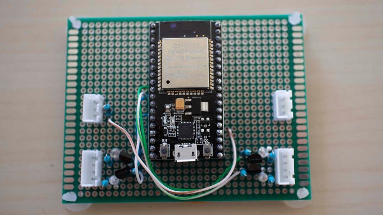
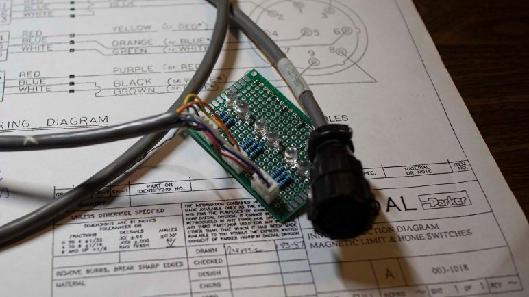
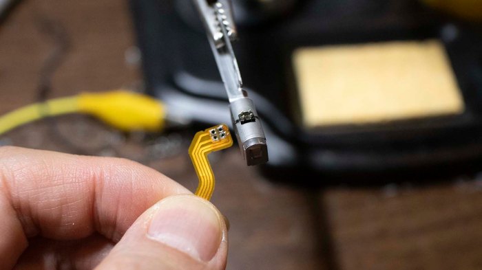
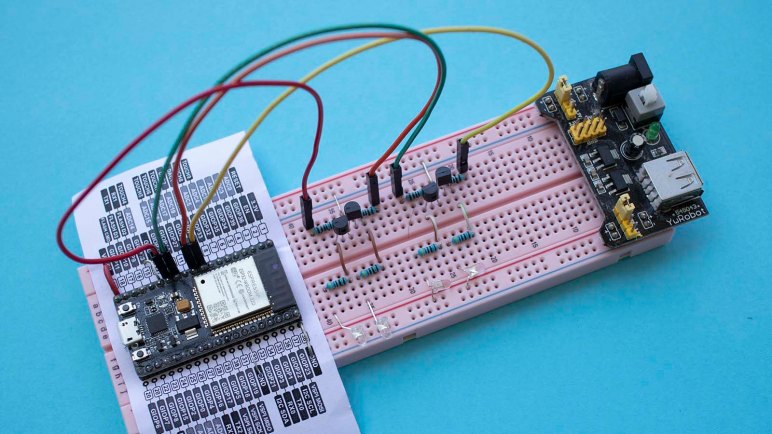
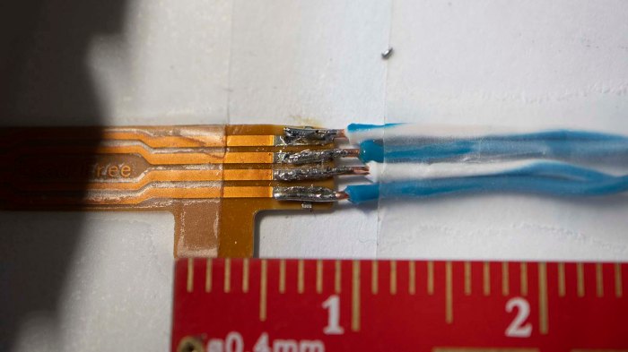
There is slightly less solder than I would have preferred on each of these joints, but several efforts to add solder created solder bridges across pins. Requiring removal by solder sucker, which reduced the amount of solder even more. Since there was enough for electrical conductivity, I left it as is to continue my experiments.


Unrelated to stepper motors or Grbl:

While I was taking the above picture to document my work, I noticed I was being watched and took a picture of the watcher. This little beauty was surveying my workbench perched on top of a cardboard box of M3 fasteners from McMaster-Carr. The spider was only about 5mm long overall including legs. Unfortunately at the time of this shot I had set it for shallow depth of field to photograph the above solder joint. I adjusted my camera to bring more into focus, but this little one was camera shy and jumped away before I could take a better shot. Still, I’m quite pleased with my camera’s macro lens.

Spider on McMaster Carr box

Panasonic UJ-867 Optical Carriage (Briefly) Under A4988 Control

Once I extracted the optical assembly carriage of a Panasonic UJ-867 optical drive, the next step is to interface it with a Pololu A4988 driver board. And just as with the previous optical drive stepper motor, there are four visible pins indicating a bipolar motor suitable for control via A4988. However, this motor is far smaller as befitting a laptop computer component.

Panasonic UJ-867 70 stepper motor connector

The existing motor control cable actually passed through the spindle motor, meaning there were no convenient place to solder new wires on the flexible connector. So the cable was removed and new wires soldered in its place.

Panasonic UJ-867 80 stepper motor new wires

Given the fine pitch of these pins it was very difficult to avoid solder bridges. But it appeared to run standalone so I reinstalled into the carriage. Where it still ran – but was very weak. Hardly any power at all. When I tilted it up so the axis of travel is vertical, the carriage couldn’t win its fight against gravity. Since the job is only to move an optical assembly, I didn’t expect these carriages exert a great deal of force. But I’ve seen vertically mounted slot loading optical drives. I thought it should at least be able to fight against gravity.

A Dell laptop charger delivers 19.2V. I’m not sure how many volts this motor intended to run at, but 12V seemed reasonable. Then I increased current beyond the 50mA of the previous motor. Increasing both voltage and amperage seemed to help with more power, but it remained too weak to overcome gravity.

As I’m tilting the metal carriage assembly in my hand, I started noticing it was warming. Oh no! The motor! I checked the temperature with my finger, which was a mistake as it was hot enough to be painful to human skin. I shut down my test program but it was too late, the carriage never moved again.

Lessons learned: don’t get too overzealous with power and check temperature more frequently.

And if I want to continue these experiments, I’ll need another stepper motor assembly.

Panasonic UJ-867 Optical Drive Carriage Extraction

The Panasonic UJ-867 is a slot loading optical drive. This particular unit was salvaged from a dead Dell XPS M1330 previously featured when I pulled its power port, and disassembled its battery, plus trying to use its AC power adapter to charge a Neato vacuum. A web search indicated this drive was better known as a drive used in certain models of Apple MacBooks. An optical drive typically has a carriage for its laser assembly driven by a stepper motor, and that carriage is my target for further stepper motor experimentation.

Panasonic UJ-867 20 Norton inside

When the lid was removed, the age of this device was clear: it still held a disk! The Windows edition of Norton AntiVirus confirms this was not from a MacBook. The year also spoke to the vintage of this drive.

Panasonic UJ-867 30 mechanicals top

With the disk removed, we can see all the mechanical linkages. This was far more than I had expected, because I had never taken apart a slot-loading drive before. Many of the pieces were involved in the slot loading mechanism, which is in the “disk inserted” position. (The Norton disk was not properly ejected – I removed the lid and popped it off!) Various mechanisms in this position block fasteners making it difficult to take apart.

Panasonic UJ-867 40 eject motor

Tracing through the mechanical bits, I guessed this motor is the heart of the drive loading and ejection mechanism. It is a simple DC motor so I should be able to put power on these pins to move the mechanism to their eject state. However, there are a few parts nearby that I might bump into if I powered from the top, so to be safe I soldered some pins from the bottom.

Panasonic UJ-867 50 eject motor wired

Applying power to this motor did indeed run through the ejection sequence, even though I’ve already removed the disk. Now it became fairly straightforward to take apart the drive.

Panasonic UJ-867 60 eject motor gearbox

Almost all of the pieces are specifically tailored to this usage, making reuse unlikely. But I do enjoy seeing the eject motor gearbox run. This is a distraction, though. The optical carriage was the goal and that was removed for the next step: connecting it to my Arduino + A4988 test breadboard.

Resuming Pololu Stepper Driver Adventures with Arduino and A4988

By the time I got around to playing with homing switches on a salvaged industrial XY stage, it was getting late. I only had a few minutes to perform one experiment: connect the normally open homing switch to X_LIMIT_PIN (GPIO02 as per cpu_map.h), set HOMING_CYCLE_0 to X_AXIS in config.h, and sent command to home X-axis. The motor moved right past the switch into the hard stops, so I turned off the ESP32 marking an unsatisfying end to the work session.

I wanted to be able continue learning Grbl while at home, away from the salvaged hardware, so I dug up the A4988 motor control board I’ve played with briefly. It’s time to get a little further in depth with this thing. Motivated by my current state in the XY stage project, the first goal is to get a stepper motor to activate a homing switch. If I could get that far, I’ll think about other projects. People have done some pretty creative things with little stepper motors controlled by Grbl, I could join that fun.

Rummaging through my pile of parts, the first stepper motor I retrieved was one pulled from an optical drive. This particular stepper motor had only the drive screw, the carriage has been lost. But with four exposed pins in two groups of two, it is a bipolar motor suitable for an A4988 motor control board. I just had to solder some wires to make it usable with a breadboard.

Since this stepper motor was a lot smaller than the one used in my previous A4988 stepper motor experience, I thought this was a good opportunity to learn how to tune the current limits on these modules by following instructions published by Pololu and using an Arduino as a test controller running code published on this page. I started with a limit of 100mA, but the motor got quite toasty at that level after running for a minute. I turned it down to 50mA, and it no longer got hot to the touch running that Arduino sketch.

This is a good start, but a motor with just a drive shaft is not useful for motion control. The next step is to find something that could push on a limit switch. I don’t seem to have anything handy, so it’s time to start digging into salvaged hardware.

XY Stage Position Detection Switches

When I built my prototype Grbl ESP32 controller on a breadboard, I thought I would get X and Y axis to start moving before looking at other parts of the system. Once I got X moving, though, I changed my mind. Instead of getting Y to run, I wanted to make sure I understand more of X. Which meant learning about limit switches and homing routine in Grbl.

But first, a look at the actual hardware, which meant picking up the other wiring harness leading inside the linear actuator. There were nine wires, only six of which were connected from its previous usage. Three of the six were connected together resulting in a total of four unique pins.

On the assumption the three wires twisted together is a common ground, I probed between it and the remaining wires. I found two of them were closed circuit and the remaining one was open. This is consistent with a homing switch and two limit switches. The homing switch is normally open and, during homing operation, the controller looks for that switch to close. When that happens, the controller knows where home is. The limit switches are normally closed because that allows them all to be wired together in series. If any limit is reached, the circuit opens, and the controller stops. For the purposes of machine protection, it didn’t really matter which limit was reached, as long as it was detected.

With the ZETA4 unplugged, the stage could be moved by hand. Watching the output from a meter wired up to these pins, I looked for positions where these switches were tripped. The initial results were very disappointing! The limit switches would trip when there were still over ~10cm of travel remaining, and the home switch is ~5cm further inside of that range. This severely constrains the usable area to a very small subset of total area. When I reported this finding to the rest of SGVHAK, I was told “Oh. Why don’t you move them, then?”

Move them?

I didn’t know these switches are adjustable to fit specific installations. In its previous life, this tables only needed to deliver a small range of its overall motion and were set appropriately. An allen wrench was all I needed to remove the cover and look inside: I saw three devices labeled Hamlin 59135, still in production and available from Digi-Key for $7.48 in single quantities. Each of these is a reed switch with a normally-open and normally-closed wire in addition to their common wire.

This explains the nine wires in the bundle: three wires for each of the switches, and the previous installation only used the common wire plus one of the other wires, leaving the remaining unconnected.

I loosened the screws holding these reed switches in place, and move them as far to the ends as I could push them with existing wiring. This still leaves approx ~3cm on either end, but I’m content to leave them as safety margin. The physical size of the home reed switch meant it couldn’t get within ~4cm of the limit switch. I don’t know if this is a problem yet. Next step: figure out how to interface these switches into Grbl.

Successful First Commands From Grbl ESP32 To Parker ZETA4

Once I could bring my breadboard prototype Grbl ESP32 controller into the shop where the salvaged XY stage lives, I was eager to hook up some wires to see if anything moves. While I put provisions for two axis on my breadboard, it felt like a good idea to start with just the X axis. It moved, but not accurately, because I had not configured the two components to match.

These stepper motors have 200 steps per revolution. ZETA4 controllers can easily handle full steps, but there are a lot of options for microsteps configurable with switches. The headache here is the lead screw: it is an old Imperial unit with a pitch of 5 revolutions per inch, but Grbl is a metric minded piece of software with everything in terms of millimeters. Using a conversion rate of 25.4 millimeters per inch, the most obvious ZETA4 microstep option that divided evenly is 25,400 steps per revolution.

The good news is that Grbl ESP32 appears fast enough to generate pulses at this speed, which is orders of magnitude beyond what I can generate with AccelStepper on an ATmega. But even with tests along a single axis, the system would halt at various times and I don’t always understand why. For example: one of the halts gave an error of “Door Open” but Grbl configuration file explicitly said to ignore the door sensor switch, so why is it stopping motion? There are more to this system I don’t yet understand.

So for the sake of eliminating potential problems, both the ZETA4 and ESP32 were configured for 2000 steps per revolution, or 10 micro steps in between whole steps. We know this is easily within the timing capabilities of the chip and, while it may introduce some error converting between Imperial and metric, it’s not the biggest problem right now so we’ll deal with it later.

These intermittent errors will likely continue as I run this system, and I will have to diagnose and debug as I go. In parallel with this, I’ve changed my plan: as my next step I will not connect the Y axis step/direction motion control pins. Instead, I will continue to refine X axis operation by getting position homing to work.

ESP32 Grbl Controller Breadboard Prototype

An ESP32 plus Grbl motion control software seems like a good candidate for running an old industrial XY table, definitely promising enough to move forward with prototyping. I had originally intended to use an Olimex ESP32 DevKitC (*) as it was equipped with two rows of sockets. This is easy to connect with jumper wires while not leave pins exposed to risk of short circuits.

This plan was short lived, because I quickly ran into a problem: The ATmega at the heart of an Arduino is a beefy 5V part that can supply up to 40 mA per pin. In contrast, the ESP32 is rather delicate 3.3V part that should not exceed 12 mA per pin. The data sheet for the ZETA4 controller I want to connect to this board expects a minimum of 3.5V to signal step and direction, which means I need external components to shift the ESP32 voltage level up to what the ZETA4 expects. When I made this discovery I was momentarily tempted to switch back to an ATmega solution, but the siren call of higher performance carried me forward.

Since I would need external components, the project brain switched to my HiLetgo ESP32 development board (*) which is mostly identical but came equipped with two rows of pins appropriate for a breadboard. Four level-shifting units were installed, each built around a 2N2222A transistor. They were connected to the step and direction pins for X and Y axis, and each received a LED (and corresponding current-limiting resistor) to indicate activity.

Staying consistent with the system I used for Glow Flow, red LEDs indicate X axis activity and green LEDs indicate Y. These LEDs allowed me to perform a quick test to verify the presence of blinking activity. Next step: connected them to ZETA4 controller to see if the motors move as commanded.


(*) Disclosure: As an Amazon Associate I earn from qualifying purchases.

Evaluate Grbl For XY Stage

I considered driving an old industrial XY table from a 3D printer controller board. I have a Melzi board on hand to use but its onboard stepper drivers were too well integrated to be easily adapted to this project. I considered running Marlin on an Arduino directly, but if I’m going to start building my own control board instead of one already tailored for Marlin, it makes sense to look at other options. Given the popularity of the Arduino platform, there’s more than one motion control project out there for me to consider.

Enter Grbl.

Unlike Marlin, which is primarily focused on 3D printing, Grbl offers a more generalized motion control platform. Provisions already in the code include pen plotting, laser cutting, and 3-axis CNC milling. All of which could be done with Marlin as well, but with different amount of code modifications necessary.

But an even bigger advantage in favor of Grbl is the existence of an ESP32 port. Marlin’s development team is working on a 32-bit hardware abstraction layer (HAL) to take it beyond ATmega chips. It looks like they’re up and running ARM Cortex boards and have ambition to bring it to ESP32. But a Grbl ESP32 port is available today and stable enough for people to use in their projects.

The headline feature is, of course, speed. While AccelStepper topped out around 4 kHz pulses, Grbl on ATmega is good for approximately 30 kHz. Grbl on ESP32 claims “at least 4x the step rates” which is likely a very conservative claim. After all, we’re comparing an 8 MHz 8-bit chip to a 240 MHz 32-bit chip. Though running on the ESP32 does incur more overhead than bare-metal code running on an ATmega, which is important in time-sensitive applications like motion control.

There are upsides for this real time operating system (FreeRTOS) overhead, as it allows the ESP32 to handle things beyond motion control. The best part employs its WiFi module to present a web-based control interface. A control interface would have required additional hardware in a Grbl machine built around an ATmega, but with Grbl on ESP32 I just need a web browser to start testing.

And since I already have an ESP32 development board (*) on hand, this looks like a great venue to explore. Let’s try running this XY stage with an ESP32 running Grbl.


(*) Disclosure: As an Amazon Associate I earn from qualifying purchases.

Evaluate Retired Melzi Board for XY Stage

In an effort to put a salvaged industrial XY table back to work, the Arduino AccelStepper was used as a quick test to see if the motors and controllers still respond to input signals. Things moved, which is a good sign, but the high precision of the Parker ZETA4 controller demanded step pulses at a far higher frequency than what AccelStepper could deliver.

The search then moved on to something that could generate the pulses required. I’m confident the hardware is capable of more, as AccelStepper topped out at less than 5 kHz signal on a 8 MHz chip. Pulsing a pin isn’t a task that requires over 1,000 instruction cycles. Given familiarity with the 3D printer world, I started looking at Marlin which runs on Arduino hardware.

The problem with running Marlin on my Arduino Nano is that I would have none of the associated accessories. No control panel, no SD reader, etc. However, I do have a full control board retired from one of my 3D printers. This board called itself a Melzi Ardentissimo and a search led to the Melzi page of RepRap wiki. Thanks to the open nature of this design, I could trace through its PCB layout. Much to my disappointment, the step and direction signals connected straight from the tiny pin on the main processor to the motor driver without surfacing in an easily tapped fashion. The intent of this board is integration and it’ll be quite some work to defeat that intent in order to decouple the processor from its integrated stepper driver.

Fortunately, I’m not limited to the world of AVR ATmega chips, nor Marlin software. There’s another very capable processor on hand waiting for such project… an ESP32 running Grbl software.

Arduino AccelStepper Under The Scope

The standard Arduino library includes a stepper motor control library. The external AccelStepper library adds the capability for acceleration and deceleration curves. I thought that would be important for driving industrial equipment as the large pieces of metal impart far more momentum than what I’m familiar with in a 3D printer.

As it turns out, I was worrying about the wrong thing. I connected my bargain oscilloscope to the output pins of my (knockoff) Arduino Nano and watched the pulses go by as I issue different commands to AccelStepper. As I issued commands for faster and faster speeds, I could see those pulses come closer and closer together until they were almost but not quite 0.2 ms apart. Running a test program in a tight loop, an Arduino running AccelStepper is indeed failing to reach 5 kHz pulse speed.

A little web search indicated this is roughly comparable to what others are saying online. AccelStepper is good for roughly 3-4 kHz and things get dicey beyond that. For the ZETA4 controller, configured to 25,000 microsteps per revolution, this is simply not fast enough to get decent speed out of the box.

How does this happen? Further web search indicated this is because all the timing for AccelStepper is done in software. Perhaps for the goal of leaving the very precious hardware timer resources for other user programs? That’s merely speculation of the design decisions involved. But one thing is certain – AccelStepper limits meant it is not sufficient for generating high frequency pulses required to drive this particular salvaged XY motion control table. I’ll have to look at something more specific for motion control, possibly a 3D printer control board.