KISS Tindie: Drum Set

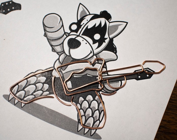
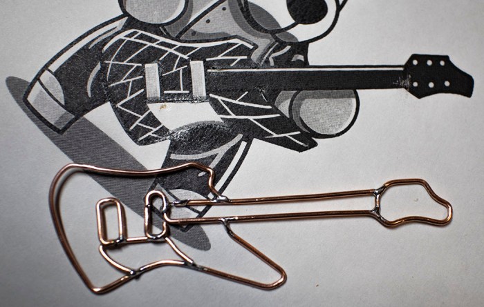
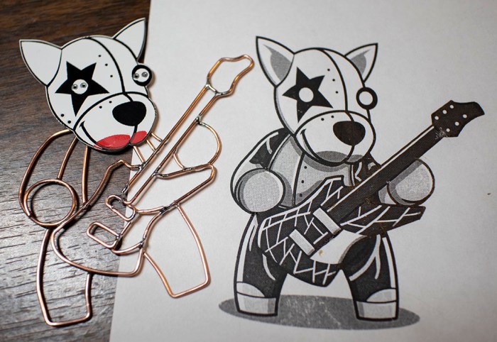
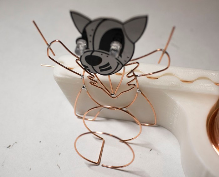
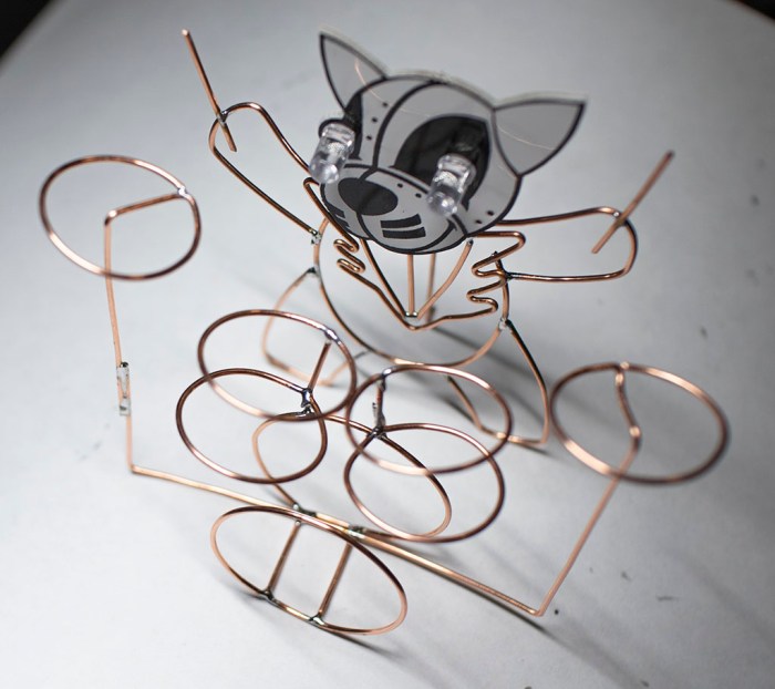
The four KISS Tindie PCB heads now have copper wire bodies, but only three of them have their instruments. They can’t go on tour like this – the drummer needs a drum set!

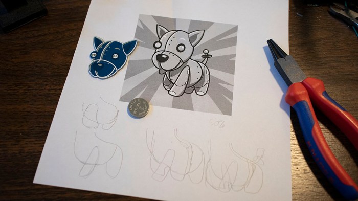
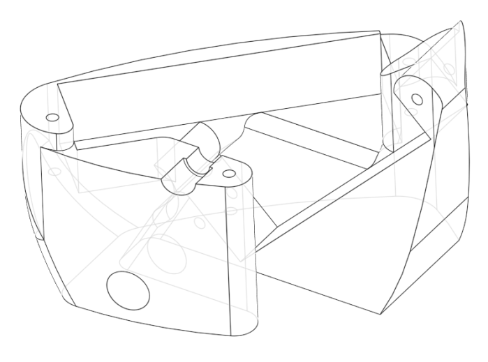
Kidding aside, a copper wire frame drum set would be a good first step into creating three-dimensional shapes using copper wire. I had thought about creating the band members’ bodies in three dimensions, but such complex shapes were above my current skill level — making it in two dimensions was challenging enough.

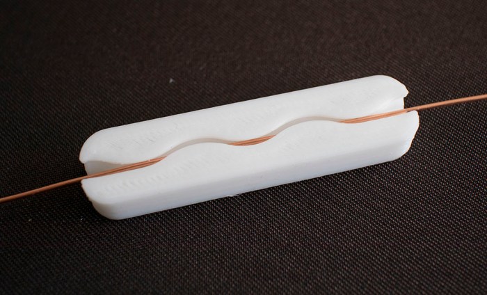
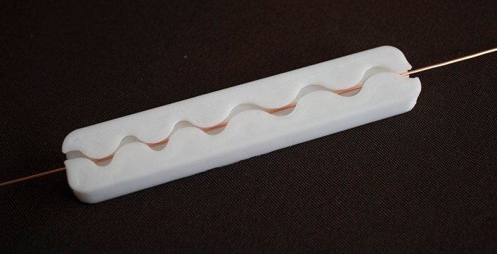
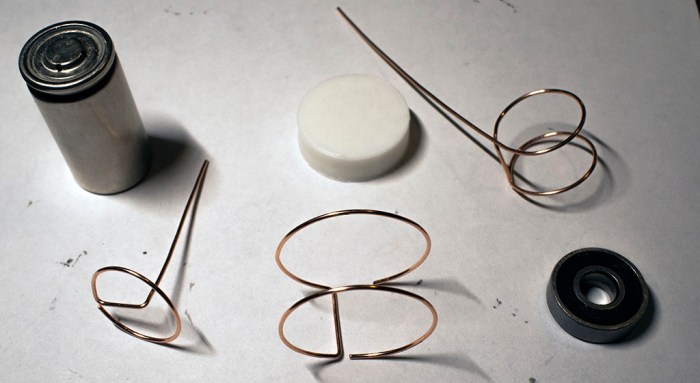
But perhaps the simpler cylindrical geometry of a drum set would be within my reach. Or at least, a simple caricature of a drum set, since everything I know came from 15 minutes of reading Wikipedia. The biggest drum that dominates visually is called the bass drum, so I started crafting cylinders to get a feel of size. I settled on this size which was shaped using a 3D-printed 30mm diameter cylinder.

tindie drummer bass drum

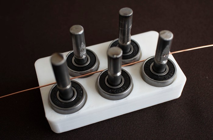
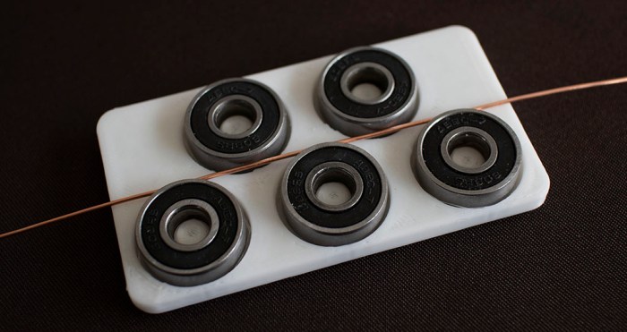
Once I picked a size for the bass drum size, I started trying every round thing on my workbench to see how well their diameter might work for the other drums. The outside diameter of a 608 bearing seemed a little too large, but the diameter of a sub-C nicad battery cell is just about right.

tindie drummer other drum components

Some wire bending and soldering later, we have a vague approximation of a drum kit as built by someone with no knowledge of drums. But it gets the point across – our KISS Tindie drummer the Catman now has a drum set.

tindie drummer with drum set

(Cross-posted to Hackaday.io)

KISS Tindies: Peter/Catman Completes The Band

Fourth and final member of KISS Tindie heads project represents the Catman. Unlike Starchild, Spaceman, or Demon, Catman is the drummer and has no guitar. This makes the figure itself easier as there’s no axe to form. The only item of any complexity were his lapels, which required sharp bends that I couldn’t quite make in copper wire. But it’s all a simplified approximation anyway so…. hopefully good enough.

KISS Tindie Peter Catman start

Soldering it together was a little tricky, but after I started using tape on Spaceman, my proficiency is now good enough for me to handle it as a problem I know how to solve.

KISS Tindie Peter Catman progress

With the chest details in place, the rest of the drummer were pretty simple.

KISS Tindie Peter Catman complete

In fact, too simple. I’m not happy with leaving the drummer standing up holding a pair of drumsticks… but more on that later. For now, I have taken the four KISS Tindie heads and, using existing reference artwork, given them simplified copper wire bodies. Here they are overlaid on top of my reference sheet.

KISS Tindie band with reference

And here they are without the reference art:

KISS Tindie band no reference

This was a fun project to trace out existing artwork using copper wire. But I’m not done yet. For starters, Catman the drummer needs a drum set.

(Cross-posted to Hackaday.io)

KISS Tindies: Gene/Demon

I know nothing about the band KISS or their music, but I have a PCB of Tindie puppy heads styled after stage makeup for the band. I wanted something to practice forming shapes with copper wire, and these looked fun. After tackling Starchild and Spaceman, next up is Demon. (All names I pulled out of Wikipedia.)

The previous two were done piecemeal: I formed one piece of wire, soldered it, then formed the next piece, then soldered that. With Demon I tried to form all the wires first before I start soldering, but tracking my pieces became difficult only about halfway through. I had to move wires around to keep them out of the way of the curve I’m actively tracing, and pieces intended for soldering (shown in this picture) were getting lost among extraneous pieces that were cut off. (Not in this picture, but certainly all over my work area!)

KISS Tindie Gene Demon pieces

Another experiment was to add some dimensional layering to the project. I retreated from building a full three dimensional body to a two-dimensional project, but I could still layer objects at varying heights to add a tiny bit of third dimension action. Seen here is the left hand (front-left paw?) behind/under the guitar.

KISS Tindie Gene Demon layers

As it turned out, soldering multiple pieces at once wasn’t noticeably faster than doing it one piece at a time. And there was a negative downside: since I’m not referencing the overall shape as I go, small errors in each individual piece added up as I didn’t have a chance to correct errors as I went. Demon ended up a little larger than the reference art, with a more distorted shape relative to the rest. But at least his axe looks good.

KISS Tindie Gene Demon axe

For the rest of Demon, I went back to soldering each piece as I bent them.

KISS Tindie Gene Demon complete

(Cross-posted to Hackaday.io)

KISS Tindies: Ace/Spaceman

Continuing the project to give KISS Tindies copper wire bodies, I moved on to the next PCB puppy head. Wikipedia tells me this one is the Spaceman. Just like I did with Starchild, I started with the guitar and built outwards from there. Bending wire is still slow going. I’m sure skilled artists and sculptors could have done it in a fraction of the time, but I won’t get better unless I practice!

I’m also trying out different techniques as I go. I struggled to hold Starchild parts together as I soldered, so for Spaceman I tried out a technique I saw in the Hackaday Supercon SMD soldering challenge: use tape to hold things in place. The picture showed high temperature Kapton tape, I just used plain desktop Scotch tape. This meant another learning opportunity: I’ve learned copper wire conducts soldering heat very well. It doesn’t take much to degrade the adhesive on Scotch tape, leaving residue on my copper wires. Thankfully the plastic substrate could stand quite a bit before it would melt as well, so the shape holds up through soldering.

KISS Tindie Ace Spaceman tape

Another novelty of Spaceman was the open loop forming his right hand. (Front-right paw?) I’m a little worried it would hook on things in the future, but I have to admit that it seems to work well visually.

KISS Tindie Ace Spaceman complete

(Cross-posted to Hackaday.io)

KISS Tindies: Paul/Starchild

With art reference in hand, printed to match scale with my KISS Tindie PCB heads, it’s time to start bending wire for my KISS Tindies project! I started with the face in the upper-left corner of the PCB, which Wikipedia told me represented “The Starchild” by Paul Stanley. The first wire I bent was for his right arm, but as I looked at my reference drawing I realized the critical part of this whole project would come down to whether I can make the guitar work in copper wire.

So I started on the guitar next. Bending wire to mimic features on my reference art. There were a lot of details on this guitar and, after thinking over how much time I wanted to spend on this project, I decided to skip out on those fine details. My copper wire curves will represent just the major character lines.

KISS Tindie Paul start

So the next question for project go/no-go is whether a simplified version of the art would look good enough to proceed. The guitar curves were painstakingly retracing in copper wire, and I decided the results were good enough to continue.

KISS Tindie Paul guitar

Here’s my simplified version of Paul’s Starchild rendered in copper wire. I think the important parts have been sufficiently represented, and I can always come back later to solder in more details if I wanted. This is encouraging enough of a result for me to proceed with the rest of the band.

KISS Tindie Paul complete

(Cross-posted to Hackaday.io)

KISS Tindies: A Wire Form Practice Project

After I built a very simple copper wire body for a Tindie blinky, I wanted to advance my copper wire forming technique with practice making something a little more complex. Looking on my workbench of stuff, the most obvious candidate for a follow-up project are the KISS Tindies given out at Hackaday Superconference 2018. They were the demonstration objects in a workshop on pad printing – people were invited to apply red to these circuit boards and take them home. Not everyone took theirs home, so extras were distributed to other interested Supercon attendees like myself.

KISS Tindies

So I could create some copper wire bodies for the band. It wouldn’t make sense to give the same dog bodies to these heads – these call for some stylized human-like poses. I thought I would have to dig deep into my meager artistic skills to draw a guitar-playing puppy, but it turns out art already existed for these heads. (It’s possible these PCB heads were actually made from the art – I don’t have the history here.)

KISS Tindies reference art

Unlike the puppy, though, there wasn’t an obvious way for me to separate these shapes into a “front” and “back” for the two voltage planes. I thought I might try to make fully three-dimensional bodies but a few tests indicate I don’t yet have enough skills as a copper wire sculptor to pull it off.

Scaling my ambitions back down to match my current skill level means the next project will take a slight step backwards in functionality: they will be flat figures, and the body won’t be a functioning circuit. The focus of this exercise is to practice wire forming on a flat plane.

(Cross-posted to Hackaday.io)

Onshape is Free For Makers, But They’re Less Eager To Say So Now

onshape_logo_mediumWhen I first discovered Onshape over two years ago, it was a novelty to see a capable CAD system run completely within my web browser. The technologies that made Onshape possible were still evolving at the time: on the client-side, web browsers had immature WebGL implementation that sometimes didn’t work, or worked unacceptably slowly. And on the server side, Onshape is an active participant in evolving AWS to work for them.

Now WebGL is a mature part of every popular web browser, including those at the heart of inexpensive Chromebooks. I’m old enough that the phrase “CAD Workstation” conjured up computer systems that cost as much as a car. With Onshape, a Chromebook can be a CAD workstation! Not a great one to be sure, but more than enough for curious learners to get started. (This page has more details on Onshape performance.)

This is why, when I started Sawppy the Rover, I switched from Fusion 360 to Onshape. Because I wanted Sawppy to be accessible to everyone, not just those who have a computer capable of Fusion 360. And I have continued to do so, not realizing another aspect of Onshape evolution had occurred.

This came up on my radar because of my super simple wire straightener project. I’ve shared simple tools before, but this one caught more attention than most thanks to a referral from Twitter (and another). I was surprised to see feedback in the theme of “I don’t have an Onshape account” and was surprised people felt it was a barrier.

When I first started using Onshape, their sign-on screen would direct people to a page where people could sign up for an account. On this screen, a free plan for makers and hobbyists was prominently displayed.

That has been removed, hence the confusion.

The free plan still exists, but it’s no longer on their “CAD Pricing” table and not mentioned in their “How to Compare Onshape Plans” guide. From the FAQ I inferred that it’s not even possible to sign up for a free plan directly, one would have to start a trial for the Professional plan, decline to pay, and be downgraded to the free plan. (I can’t test this hypothesis myself since I already have an established account on the free plan.)

I personally find this disappointing, but I’m not surprised. Onshape is a business and businesses have to be profitable or they’ll disappear. I’m a little afraid this might mean they’re working to phase out the free plan, but even in that case I hope they offer a subscription tier that’s priced reasonably for hobbyists on tight budgets.

LEGO 41611: BrickHeadz Marty McFly and Doc Brown

Today will be a little holiday break from the usual fare… it’s time to play with LEGO bricks!

I count Back to the Future as one of my favorite movie series, a fact known to most of my friends. So it’s no surprise that I had been gifted a Back to the Future themed LEGO set. Kit #41611 from their “BrickHeadz” line of caricature figurines represented our stars Doc Brown and Marty McFly. This is my first BrickHeadz set and I was very curious to see how they would come together.

Our heroes are depicted as they were at the beginning of the first movie, when Doc demonstrated time machine operation for the first time in the parking lot of Puente Hills Twin Pines Mall. Marty is in his puffy 1985 jacket holding a VHS camcorder, and Doc is wearing his white lab coat with radiation symbol on the back and holding the car’s remote control.

These kits minimize appearance of LEGO studs, using a lot of smooth pieces to create the desired appearance. This is especially apparent in the face and hair. Marty had many smoothly curved pieces, whereas Doc had a much more random jumble of pieces to represent his wild Einstein-like hair.

When I poured all the pieces out on the table, I wondered about a few pieces that were brightly colored in a way that did not match the color theme of the character. As I followed instructions, I learned these pieces would not be visible when properly assembled. Hence these oddly colored pieces were designed to be a visual indication if assembly should go wrong. Here’s a partially complete Marty, the bright pink and bright green pieces sit inside the body and head, invisible when properly assembled.

LEGO 41611 1 partial Marty

Once Marty was complete, it was time for Doc. Again, the bright pink, yellow, and green pieces would not be visible when properly assembled.

LEGO 41611 2 Marty done time for Doc

And here is Doc and Marty, ready for their adventures through time. It’s very generous of LEGO to give a few extra small pieces that are easy to lose. Assembling both of them consumed approximately 30-45 minutes, and I enjoyed every minute of it.

LEGO 41611 3 Doc and Marty


A Copper Wire Body For Tindie

With the wire spool ready to go, it’s time to tackle a simple starter learning project. For the subject I turned to the simple Tindie blinky badge. The badge itself is a soldering exercise, and now it will also serve as a freeform circuit exercise: I will give the Tindie puppy a copper wire body!

Tindie copper body 4 with tail

There will be two loops of wire, one will be electrically connected to battery positive, other loop will be connected to battery negative. There are two existing positions for LEDs on the badge, and I will be adding a third LED to give Tindie puppy a flashy tail. Each LED will bridge the two loops of wire for power.

The Tindie logo was printed up, scaled so printed head matches circuit board size. Then I start tracing out curves as nominees for positive and negative loops.

Tindie copper body 1 planning

Once I had a plan, three segments of wire formed the positive loop, which has Tindie’s two left legs and most of the body.

Tindie copper body 2 front

The negative loop has Tindie’s two right legs and some duplication of body curvature. I had to make sure it reached back far enough for the tail LED to get power. The two loops also formed a battery holder between them. It was important for the battery to be in the body if I wanted Tindie to sit on paws, because if I used the default battery holder in the head our puppy would topple over from being too top-heavy. And the natural place to put a battery in the body is in the chest, as heart of the machine.

Tindie copper body 3 front and back

Some soldering work later, Tindie is standing on paws of a shiny copper wire body, complete with blinky tail. Since the two loops of wire are only held together by leads of the three blinking LEDs, it is rather fragile. For future projects I need to find additional ways to brace positive and negative loops without short circuiting them. Either more electronic components or non-conductive structure.

(Cross-posted to Hackaday.io)

Copper Wire Spool Holder With Straightener

Now that I’m warmed up to make circuit sculptures, it’s time for more practice. And for that practice, I’ll need wire and lots of it. Most of the projects I’ve seen are built from straight rods of brass that I could procure from the local hobby shop. However, I personally prefer the color of copper (though it will suffer from oxidation) and I can get copper wire fairly inexpensively in a large spool. But of course, that wire would need straightening.

Thus the next project: A holder for a spool of wire that includes a straightener. For reference on straightener, I looked at CNC wire bending machines of both the DIY variety and an industrial offering, both of which featured similar wire straightening mechanisms. Then I tried to replicate my own using my stock of cheap 608 bearings and metal 8mm shafts left from my Sawppy rover project.

Version 1 was a very simple base that laid out the five shafts in the arrangement I wanted. I neglected to consider wire behavior so they ended up getting caught under the bearing.

Wire straightener 1

Version 2 addressed that issue by raising its working surface so wire would not get under bearings. However, a 3D printer has problem holding precise tolerances and so shaft holes had to be drilled out before the shafts would fit. This changed position enough that final bearing spacing didn’t work well.

Wire straightener 2

Version 3 attempted to eliminate variability of shaft position by eliminating the shafts entirely – have bearings sit on 3D-printed posts. Unfortunately position errors were even worse!

Wire straightener 3

After stopping and thinking about the problem, I thought perhaps I’m over-complicating the device. As an introduction, I’m only dealing with 18 AWG wire. This is fairly easy to bend so perhaps I don’t even need bearings – simple shapes might be enough. Hence version 4 replicated the round (but not rolling) surfaces in a wave.

Wire straightener 4

Version 5 tried to improve by having a second stage with different spacing. This is an improvement. A mild one, but an improvement nonetheless.

Wire straightener 5

Version 6 integrated version 5 into a spool holder.

Wire straightener 6

Since I’m not using bearings, friction is quite high. It would not be acceptable if I were trying to build a CNC wire bending machine (a potential future project) but for manual use it’ll do for now. Using a pair of pliers, I can grab and pull on the end to give me wire straight enough for the next few projects.

Onshape CAD file is publicly available here. Adjust dimensions to fit your 3D printer’s characteristics, then export to STL for printing.

UPDATE: Onshape has a free subscription tier for makers, even though it isn’t as prominently advertised as it used to be.

(This page has also been posted to Hackaday.io)

Freeform Fun with Salvaged SMD LEDs

There’s a freeform circuit contest going on at Hackaday right now. I’m not eligible to enter, but I can still have fun on my own. I haven’t had any experience creating freeform circuit sculptures and now is as good as time as any to play around for a bit.

Where should I start? The sensible thing is to start simple with a few large through-hole light-emitting diodes (LEDs), but I didn’t do that. I decided to start higher up on the difficulty scale because of a few other events. The first is that I learned to salvage surface mount devices (SMD) from circuit boards with a cheap hot air gun originally designed for paint stripping. I had pulled a few SMD LEDs from a retired landline telephone and they were sitting in a jar.

The second is the arrival of a fine soldering iron tip (*). I had ordered it in anticipation for trying to repair a damaged ESP32 module. I thought I should practice using these new tips on something expendable before tackling an actual project, and a freeform exercise with salvaged SMD LED seems like a great opportunity to do so.

As a beginner at free form soldering, and a beginner at SMD soldering, the results were predictably terrible. I will win no prizes for fine workmanship here! But everyone has to start somewhere, and there will be many opportunities for practice in the future.

7 survivors light

It’s just a simple circuit with seven LEDs in parallel, on the lead of their shared current-limiting resistor. Not visible here is another aspect of learning to work with surface mount components: they are really, really small. I had actually salvaged nine LEDs. Two of the nine LEDs have flown off somewhere in my workshop and didn’t make it to the final product.

9 salvaged LEDs

For comparison, here is the “I ❤ SMD” soldering kit that was my gentle introduction to surface mount soldering. The LED in that soldering kit were significantly larger and easier to manipulate than those I salvaged from an obsolete landline telephone.

SMD intro size comparison

Moral of the story: for future projects practicing SMD assembly, be sure to have spare components on hand to replace those that fly off into space.


(*) Disclosure: As an Amazon Associate I earn from qualifying purchases.

Royal Purple Lissajous CRT

I brought my laser Lissajous curve machine (that degraded into a not-Lessajous curve machine) to our SGVTech meet, but it was not the only one there. [Emily] brought her salvaged CRT that she intends to turn into a Lissajous machine as well. Since I had brought my amplifier with me for my machine, it was easy to disconnect my contraption and connect to hers instead. Now, the stereo amp will be driving the CRT’s horizontal and vertical deflection coils instead of speakers. Unlike the last time we hooked this amp up to a CRT in this manner, we now have LRWave to control left and right audio channels independently.

Violet Lissajous back

This CRT was originally a black and white unit. To add some visual interest, [Emily] has coated it with Krylon Royal Purple Stained Glass Paint. I think the change is subtle but effective at communicating this is something special.

Another change for this experiment: we’ve switched platforms from Android to running LRWave on an old MacBook Pro. We’ve had recurring problems with random pops and crackles in output waveform, and since it’s a problem shared with the native signal generation app across three different Android devices, I suspect the root cause is somewhere within Android OS. Hence switching to MacOS as a change of pace to see if it also has the cracks and pops heard when running on LRWave. Or in the case of a CRT, seen on-screen as a sporadic scrambling of the curve. The switch was a good move. We had no unexpected noises for the rest of the night.

Violet Lissajous front

We got some very pretty curves, far better than what I got out of my laser LED and speaker apparatus. And unlike the speakers, a CRT deflection coil does not degrade as we send different wave forms through it. We had smooth curves throughout the entire test session, it did not degrade into squiggly abstract modern art.

Violet Lissajous closeup

Observations from the night:

  • LRWave can generate a more consistent signal running on MacOS than on Android.
  • Laser + mirrors + speakers are indeed accessible at lower cost and lower voltage, but speakers suffer damage when forced to reproduce arbitrary wave forms. Further evolution of my idea would require finding a different actuator to replace speakers.
  • CRTs can produce beautiful Lissajous curves, far smoother than any pixel-based flat panel display can. Furthermore, their deflection coils seem to suffer no damage from arbitrary wave forms pushed through them.
  • When a salvaged raster CRT like this unit is run at low speeds, there is a visible gap in the line that [Emily] credits to the beam occasionally cutting out for vertical blanking interval. Its effect can be mitigated by running at high speeds, or be used as intentional visual effect at low speeds.

[Emily] plans to spray a matte coating to reduce distracting reflections. I look forward to future progress on this project.

Laser Lissajous at SGVTech

The main reason I wanted a less delicate and more portable form for my laser Lissajous project is that I wanted to bring it to show-and-tell at SGVTech meetup. I got it printed and assembled a half our before the meet. I verified it could make a basic Lissajous curve and then it was time to go.

It was an interesting piece of novelty for show-and-tell. The laser was difficult to see against the ceiling of the space, so I ended up tilting the contraption on its side so the laser is projected sideways onto a taped-up sheet of white paper serving as screen.

I started the night with sine waves that produced decent Lissajous curves. Then we started playing around. LRWave allowed us to feed different wave forms in – triangular, sawtooth, and square waves. Each produced their own wild patterns, but after a while we noticed some changes in the system. Reverting back to sine waves no longer reverted to soothing sounds and smooth curves. Looking over the apparatus, we found that a speaker has rattled itself loose. Tightening fasteners back down did get us some of the curvature back, but could not eliminate all the extraneous vibrations affecting the curve. Something else is degrading. Either the hot glue holding mirrors to the speaker, or the coil inside the speakers.

By the end of the night, between all the potential variables of speaker degradation, glue adhesion failure, mirror flex, and extraneous vibration in the system, the laser curves stopped being Lissajous curves and started becoming wild abstract modern art. It had come full circle: I started this with a 3D-printed stand that was a tribute to Frank Gehry. By the end of the night, the laser projection started resembling Frank Gehry sketches.

Decayed Lissajous laser curve

3D-Printed Laser Lissjous Apparatus

Copper wires and helping hands are fine for my laser Lissajous rough draft, but it’s fragile and nearly impossible to take elsewhere. It’s time to design and 3D-print a more rigid and portable version of my cheap & cheery laser light show.

The fundamental task is not difficult: note the final arrangement of components in my rough draft, put them into Onshape, and create a housing for those parts with the help of Onshape in-context modeling. However, the geometry requirements of mirror and laser placement resulted in quite an awkward layout of components involved.

I looked at component layout in 3D space inside Onshape and spent a few hours trying to find a good way to package them all together. After a few fruitless hours trying to create something that I find pleasing to my existing sense of aesthetics, I decided to take this opportunity and go in a different direction instead: I’m going to channel my inner Frank Gehry for packaging these components.

Lissajous bracket 2 wireframe

This is my take on a wild asymmetric shape that still serves all the requirements of the project, much as how Gehry architecture have many features that seem wild at first glance. Their jarring exterior masks the fact it still creates the interior volume and structural support necessary for the building. For me, this was a fun way to experiment with contour and curvature tools available in Onshape and difficult to represent in OpenSCAD.

Lissajous bracket 2

When assembled, my apparatus can create fairly decent Lissajous curves. Not as nice as those [Emily] and I created on a CRT, but a lot more easily reproducible by anyone with access to a laser pointer, a pair of speakers, and some mirrors. It also allows me to take it around for show-and-tell with other makers.

Helping Hands For Laser Lissajous Rough Draft

With small plastic mirrors now installed on salvaged laptop speakers, it’s time to put them to work. With their far smaller size, I could place the mirrors much closer together. This is important because if they were too far, beam deflected from the first mirror would spread out in a wider arc than that the size of the second mirror. This was a problem with the initial proof of concept rig, especially when I explored maximum deflection which ended up burning up a speaker. Now, these compact speakers allow mirrors to be only about 15mm apart.

These speakers were again powered by the same thrift-store stereo amp, but keeping in mind the lessons from the last round, I’m more careful about the amp’s output volume. The next challenge was to find ways to hold all the components involved as I experiment with direction, angle, and orientation. Since I only had two hands and there were three components (two speakers and a laser) I needed to summon help.

The laser was taped to a stiff strand of copper wire which I could bend at will to aim the laser. For the speakers, I had two sets of helping hands which typically help me solder electronics together but today they are mirror holders. Their alligator clips hold nice and strong to mounting brackets formerly used to secure these speakers inside a laptop chassis. Together they helped me determine an arrangement that would produce the results I sought. Now I could take what I’ve learned and make it more permanent with a 3D-printed chassis.

Dell Inpsiron speaker Lissajous first draft with helping hands

Installing Mirrors On Laptop Speakers

I set out to use mirrors attached to speakers to deflect a laser beam into Lissajous figures. After I’ve destroyed (and taken apart) a speaker to prove the concept worked, I need replacement speakers to move forward. Searching through my parts bin for replacement speakers, I found another pair salvaged off an obsolete Dell Inspiron 6400 laptop. Given the track record so far, I do not expect these speakers to last long, but the journey should be fun.

Dell Inspiron 15 speakers

The proof of concept used blue painter’s tape. This time I’m going for a little more permanence with mirrors hot-glued to the speaker surface. Since these speakers are tiny, I need to cut my stock of plastic mirrors down to size. The first cut using scissors immediately signaled no-go: the plastic is brittle sending cracks along the cut.

Plastic mirrors too brittle cracks when cut

So instead of cutting with scissors, we’ll cut a shallow groove into the surface with a knife, then applying pressure with a pair of pliers to make it break along the groove. This technique also works for real glass mirrors as well, but glass would require a diamond-tipped cutter to form the groove and probably something other than pliers to apply force.

Plastic mirror score and break

I broke the plastic mirror into little octagons, which are close enough to a circle for today’s fabrication exercise. Trying to attach them, though, found another problem with plastic mirrors: heat deformation. I put some hot glue directly on the back of my first octagon mirror, and watched it deform from heat. Oops.

Plastic mirror damaged by heat

I switched to putting glue on the speaker first, then waiting a few seconds for the glue to cool. Before the glue solidifies, I apply the mirror. Success! I now have two small speakers with small plastic mirrors attached to them. Next up: lasers.

Mirrors installed on Dell Inspiron 15 speakers

Burnt Speaker Teardown

There was a casualty of my laser+speaker Lissajous proof of concept: while exploring the limits of how far I could push a speaker, I went too far and burned one up. It was an unfortunate but expected part of playing with using components outside of their designed purposes. And now the dead speaker has one final role to play: as a dissection subject so we can see what’s inside. This is a irreversibly destructive process because speakers are not built to be disassembled and repaired. Once I plunged the blade into the speaker surround, I am committed.

Cut speaker surround

Once the surround was cut, I could access and cut the suspension underneath. After they were both cut I could lift the cone. Several problems were immediately visible. The voice coil that should have been attached to the bottom of the cone has separated, leaving a ring of charred material and a single thin strand of magnet wire. Emphasis on single: there should have been two wires for the coil! Also, lifting the cone released a strong odor of burnt insulation.

Speaker cone lifted

Since that thin strand of magnet wire is our only connection to the voice coil carcass still buried within its narrow slot, the only thing to do is to tug on it (gently) to unwind the coil. As wires were pulled, they occasionally brought up flakes of burnt speaker with them. Eventually, enough of the obstacles were removed that the charred remains of the voice coil could be recovered. It’s a pretty sorry sight and a fitting company to the smell.

Speaker voice coil recovered

I originally had the ambition of creating my own voice coil actuator out of the damaged chassis, by winding magnet wire around a 3D-printed replacement cone. But that’s before I saw how narrow the slot was. I could not make anything to fit in that slot, so the re-purposing plan was abandoned. We’ll just keep the big chunk of magnet because magnets are always fun. (Keep away from credit cards, though.)

The magnet assembly was held on to the speaker chassis by four big rivet-like structures. A drill press was summoned to remove the bulk of the metal. It was novel to see metal shavings align themselves to the magnetic field.

Speaker on drill press

After the majority of the rivet were removed, the chassis was placed in a vice and the magnet assembly was pried loose from the chassis.

Speaker magnet pried loose

This still left four protrusions to cut flush, and the tedious task of cleanup – the metal chips really wanted to stay with the magnet! But by the end of the night I have a hefty speaker magnet assembly.

Laser+Speaker Lissajous Proof of Concept

With LRWave 1.0 complete, I could focus on the mechanical bits of a Lissajous machine driven by that web app. The goal is to build a more accessible Lissajous machine that does not have the risk presented by high voltages involved in driving a CRT. It will not look as good as a CRT, but that’s the tradeoff:

  • High voltage electron beam in a CRT replaced by far lower voltage LED laser diode.
  • CRT deflection yokes replaced by audio speakers.

The proof of concept rig is driven by the same thrift store amplifier used in the successful CRT Lissajous curve demo. This time it will be driving speakers, which is what it was designed for, instead of CRT deflection yokes. The speakers came from the same source as that CRT: a Sony KP-53S35 rear projection television we took apart for parts so we could embark on projects like this.

Hypothesis: If we attach a mirror to a speaker, then point a laser beam at that mirror, the reflected beam will be displaced by the movement of that speaker. By using two speakers and adjusting beam path through them, we can direct a laser beam among two orthogonal axis X and Y via stereo audio waveform generated by LRWave.

For the initial test, mirrors were taped directly on speaker cones and arranged so laser beam is projected to the ceiling. This produced a satisfactory Lissajous curve. Then the mirror configuration were changed to test another hypothesis: instead of direct attachment to speaker cone, tape the mirror so it sits between the fixed speaker frame and the moving speaker cone. This was expected to provide greater beam deflection, which it did in the pictured test rig. However, the resulting Lissajous curves were distorted due to flex by the plastic mirrors and not-very-secure tape.

RPTV Speakers and masking tape

Experimenting with maximum deflection range, I pushed the speakers too far and burned one up. For a brief few seconds the laser beams were visible, reflected by the smoke of an overloaded speaker coil.

  1. I could see the laser beams, cool!
  2. Um… why am I able to see the laser beams?
  3. [sniff sniff]
  4. Oh no, the magic smoke is escaping!

The Lissajous curve collapsed into a flat line as one deflection axis stopped deflecting, and that ended experimentation for the day.

LRWave 1.0 Complete

The (mostly cosmetic) fine tuning have been done and the LRWave web app is sitting at a good state to declare version 1.0 complete. Now I can move onward to the hardware components of my laser Lissajous project.

LRWaveV1.0

Some tidbits worthy of note are:

  • MDC Web theme colors can be applied via CSS styles as per documentation. What’s (currently) missing from the documentation is the requirement I also have to add @import "@material/theme/mdc-theme"; to my style sheet. In the absence of that import directive, the theme CSS styles have no effect, causing me to bang my forehead against a non-respnsive brick wall. Now the following visual elements finally worked as designed:
    • App has a dark background, because I’m building this for a laser Lissajous curve project and I expect to use this app mostly in the dark.
    • The column titles “Left” and “Right” now has theme colors.
    • The waveform drop-down box options are now visible and not white-on-white. (Change is not visible in screenshot.)
  • Web Audio API implementation in Chrome would cause audible pops when pausing or resuming playback. This is true even if I write code to fade volume. (Fade out to zero upon pause, fade in from zero upon resume.) Since this fade code added complexity to my app but failing to eliminate the audible pops, I did not commit fade code to my app.
  • The browser tab favicon now works… I am not sure why but next item might be related:
  • I’ve added an instance of the icon to my app’s background. Now there’s a little app icon at top center of app background. Perhaps this change helped kicked the browser favicon code into action?
  • Responsive layout is much improved – the app was always fine in portrait mode in a compact phone resolution, but now it no longer looks embarrassing on larger displays.
  • Added support for Safari browser. (Safari uses webkitAudioContext while other browsers use AudioContext.)
  • Wrote up a README.md for the project.

The whole project was done via Cloud 9 IDE. My AWS cost for this experiment was a grand total of $0.43.

LRWave EC2 Cost

Github project: https://github.com/Roger-random/lrwave

Published live version: https://roger-random.github.io/lrwave/

LRWave Core Functions Complete

After a few hours of JavaScript coding, all the core functionality I set out to implement is running. At least, at a basic level. (This link will go to the live version of LRWave, which should continue to improve as I learn.)

  • Two-channel (left and right) function generator
  • Frequency adjustment
    • User can type in anything from 0 to 24 kHz
    • Buttons to adjust frequency up/down in 1Hz steps.
  • Waveform selection available in Web Audio API
    • Sine
    • Square
    • Sawtooth
    • Triangle
  • Gain adjustment
    • User can type in anything from 0% to 100%
  • Play/pause button.

LRWave on Nexus 5

Since I hate web pages that start playing some sound upon load without user interaction, I don’t start playing sound until the user has pushed the play button. It turns out I have accidentally followed the guidance from Google, which will not allow pages using Web Audio API to play sound before user input. I don’t always agree with Google, but I’m glad we’re aligned here.

The JavaScript portion of this project have been relatively easy. I found Web Audio API to be straightforward to use in my simple little function generation app. There are some refinements to be made: there are audible pops as settings are updated. Right now I perform those updates immediately, but they should ramp from old to new value in order to avoid abrupt changes. Everything else dealing with user interface are standard event handler code.

What I found challenging is the aesthetics side of things. Proper HTML layout is still a struggle for me, but I know projects like this will eventual lead to mastery (or at least competence) with responsive web layout. In the meantime, my app looks fine on a phone in portrait orientation but things start to get weird quickly as browser window size grows.

Individual components in MDC Web have worked well so far, with the exception of the slider control. I tried to use it for gain but it didn’t behave as I expected so, after a half an hour scratching my head, I set it aside for later. Another difficulty was MDC theming. I wanted the background to be black and I haven’t found my mistake when trying to do it within MDC theming module.

On the web browser interaction side, I designed an icon and added a reference in the header. Google Chrome recognizes it enough to use the icon on the recently opened sites window, but it doesn’t use the icon on the browser tab and I don’t understand why.

Lots of learning so far, but more learning plus refinement ahead…