Hard Drive Brushless Motor as Generator

Some time ago I had a broken hobby servo that I traced to a burned-out control board. Since the motor itself and its geartrain are still good, I thought I could use it as a gearmotor but I didn’t have an immediate project. What I did have immediately on hand was a few LEDs on the workbench, so I reversed the power flow: I connected the LED to the motor and spun the servo shaft. The former output shaft is now where I input my mechanical energy, and the former motor power input pins have become electrical output pins of a very simple and crude power generator. Making the LED glow a dull red was fun for a few minutes before some gears failed. Clearly, there is room for improvement.

I think of that experience every time I take apart a failed hard disk drive, which I do for a few reasons: first, because I wanted the powerful magnets within a hard drive. Second, because disassembling the data platters make my data very difficult to steal. And third, because all that precision machining is very pretty to look at! The typical finish line for this activity is a hard drive chassis with a brushless motor that formerly spun the platters.

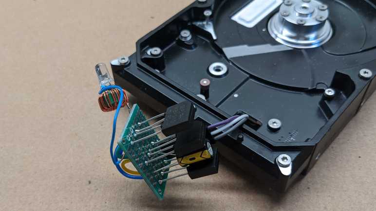
I’ve wanted to try turning such a motor into a generator as well, a more complex project that I had put off until now. I started by soldering wires to the motor’s three input pins.

From here I could connect any two of these three wires to my cheap oscilloscope. When I spin the motor by hand, I can see a small sinusoidal AC signal. There should be three sets of these waveforms, one between each pair of wire. (1-2, 2-3, and 1-3.) In order to convert this to DC power suitable for lighting up a LED, I will need rectifiers to turn that AC power into DC. I have a motley collection of rectifiers salvaged from various electronics teardowns, but I don’t know if it is important that I use three matching units. Since they are cheap, I decided to buy a pack of twenty rectifiers(*) just so I have three identical units for this experiment.

Rectifiers in hand, I picked two out of the three wires from my motor and wire them up to the two pins labeled “AC”. Repeat for two more rectifiers each for one of the other two wire pairings, then connect all three “+” and “-” together in parallel with a capacitor. I then put my DC voltmeter across them and started playing with the motor spindle. Unsurprisingly, there’s some kind of startup barrier. If I just casually spin the motor about the same speed I turn the volume knob on audio equipment, nothing happens. But if I give it a fast twist like I’m spinning a top, I can see the capacitor voltage jump to about 1V.

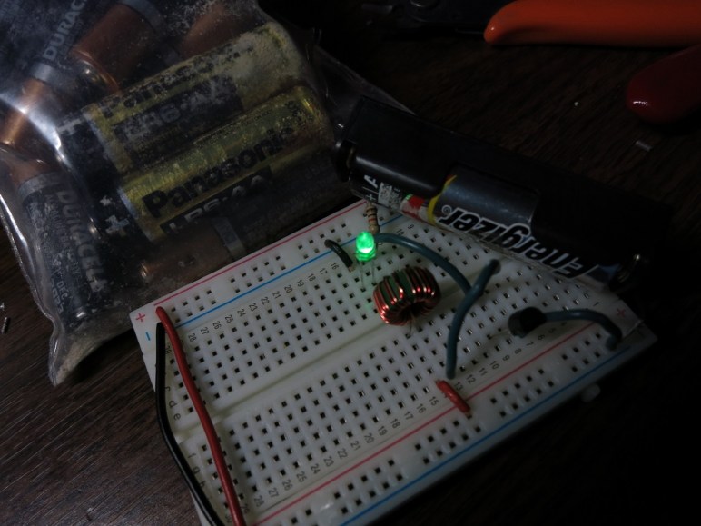
A single volt is not enough to directly illuminate a LED, but I have built lots of little “Joule thief” boost converters that can light LEDs from tired alkaline batteries. They only need about 0.4V to do their thing, but I don’t know if there’s enough current. I soldered one of them to this circuit and gave the motor a good twist. I was rewarded by a brief blink of LED. I count that as success!

The next step in this exploration is to build something so that motor can spin faster and more consistently than what I can accomplish with a flick of the wrist. What form of mechanical energy should I try to harness for power generation?


(*) Disclosure: As an Amazon Associate I earn from qualifying purchases.

Building a Tiny “Joule Thief”

Yesterday I got a “Joule Thief” (a.k.a. Armstrong self-oscillating voltage booster) circuit up and running on a breadboard. The circuit was more complex than it needed to be, with a tangle of wires, because things got messy while debugging. But now that I know which parts connect to which, it’s time to simplify.

The goal is to make it small and compact enough to package together as a single-battery LED flashlight. That general goal broke down to the following parts:

  1. Minimize physical size. Since the coil is the largest single piece (other than the AA battery) it makes sense to align the diameter of the coil to the battery and pack everything else as tightly inside as I can.
  2. Minimize component count. Most Joule Thief examples on the internet (including the top picture on the Wikipedia page) soldered the legs of the individual components together. No circuit board needed.
  3. Friendly to hand soldering. There are some ready-made Joule Thief circuits for sale on the internet using surface mount components and a circuit board. I wanted something I can build by hand and maybe use as a soldering teaching project to be shared on the internet.

After a few iterations, I have something I’m happy to share with the world. This is purely about the mechanical assembly – the electronic schematic is identical to the one in the Wikipedia article linked at the top of this post.

An overview in words:

  • The resistor for the NPN transistor base is installed between the collector and emitter. The resistor acts as physical separation in order to avoid a short-circuit.
  • The transistor and LED are pointing in opposite directions, allowing their pins to point towards each other and soldered together. The aforementioned resistor keeps the LED anode and cathode separate.
  • The transistor is stuffed into the middle of the coil, utilizing the center volume.

The build sequence in pictures:

1 - Transistor
Transistor with the base bent in preparation for resistor installation.

2 - Transistor Resistor.jpg
The 1K Ohm resistor is installed on the base, between collector and emitter.

3 - Transistor Resistor Coil
The coil has two wires wound together. One end of this dual-coil is facing the camera, the other end facing away. Since we need to wire up the coil in opposite directions, we’ll bend one wire of the front pair towards the back, and the opposite back side wire to the front.

4 - Coil prep.jpg
The two wires now facing away from the camera are soldered together to become the positive terminal of the circuit. One of the two wires facing the front will be soldered to the resistor, and the other to the emitter.

5 - Transistor in Coil
Transistor in the center of the coil. Now the coil wires can be soldered.

5a - Resister soldered
Resistor soldered to one coil wire, all the others have been trimmed short in preparation for attaching the LED.

6 - LED
LED is soldered to the circuit, as is a wire to act as negative (return) wire.

7 - AA
Install the whole assembly in front of a 3D-printed AA battery tray: Let there be light!

Building a “Joule Thief”: Adventure in Analog Electronics

One of my early memories as a little kid playing with my battery-powered toys was the realization that battery exhaustion is not an absolute thing. A set of AA batteries that could no longer run a motorized toy aren’t completely useless – they could be installed in an electronic toy and make that light and beep. I turned it into a little game for myself: swapping batteries around trying to figure out which tired worn batteries would work in which toys.

A well-meaning adult saw this activity and thought they saw a poor child frustrated by dying batteries. He or she (I have no memory of the person, only their action) tried to help by taking away the worn batteries and giving me a fresh pack of AAs. They were understandably confused when their well-intended kindness were rewarded by an upset toddler in tears.

Many years later I would learn how electric motors demand more current than microprocessors along with their effect on battery power output, thus explaining my childhood observation. I understand what’s going on now, but I still try to pull every bit of power out of a non-rechargeable battery before they are disposed.

Which is why my eyes lit up when I learned of a circuit that can power a LED from a “dead” battery. Wikipedia says the official description is “Armstrong self-oscillating voltage booster” but it’s filed under “Joule Thief“, the pun name that I usually see.

This type of electronics projects venture beyond the digital world I’m familiar with. There’s no voltage representing 1 and 0, instead it works with voltage that oscillates. Specifically, I’ve never worked with the fields generated by wires coiled around a toroid core. The first few attempts – using either hand wound coils or savaged from electronics – failed. And I didn’t understand enough to diagnose if it’s the coil or the circuit.

This time around, I took a shortcut: I bought a pack of coils (*) with customer comments that confirm they can be used for building Joule Thieves. This way, if the circuit didn’t work, I knew it was my fault and not the coil. And indeed, the first few attempts failed because the coil was not correctly connected to the rest of the circuit. (The key phrase I missed in the Wikipedia article: “the two windings are connected in opposing directions”.)

Attached is the picture of the first iteration that actually worked, powered by a “dead” AA battery. This circuit is unnecessarily complex because I had been moving parts and wires, around trying to understand where I made my mistake. But now that I have a working Joule Thief I can start simplifying and make a more compact version.


(*) Disclosure: As an Amazon Associate I earn from qualifying purchases.