Sawppy and SGVHAK Rovers at SGVLUG May 2018 Meet

SGVLUG201805

Yesterday was the monthly meeting of San Gabriel Valley Linux Users Group (SGVLUG) for May 2018. SGVHAK, the maker hacker group who built a rover, is a subset of SGVLUG and we got to present our project to the wider community.

The night’s presentation started with Eric Junkins of JPL talking about how JPL’s Open Source Rover came about. Several groups were invited to beta test the build instructions before public release and that was the stage where SGVHAK got involved. SGVHAK made a few changes to the baseline design for our own take on the project, exactly as the nature of open source release intended.

Towards the end Sawppy the Rover got a few minutes in the spotlight as a spin-off rover that was inspired by JPL’s Open Source Rover project. I got to talk about how it came out of an offhand comment by Eric and eventually I delivered a basic chassis that met his challenge of a $500 price point. It is not as fast, nor as powerful, nor as flexible as the JPL open source rover design. These were all trade-offs made in the name of hitting that price point.

After the presentation both rovers ventured out to the parking lot behind our meeting location (Du-Par’s Pasadena) and ran around for a while, attracting attention from passers-by along the way. The rovers may have managed to recruit a few new members to SGVLUG. We’ll see!

Sawppy Feet 1.0: Rover Wheel Design for 3D Printing

Based on past experience building with aluminum extrusions and 3D printing, I was confident I could build most of the rover structure. The construction technique I used had been evolving through the Luggable PC projects and was further refined by building Sawppy. It ended up as a Hackaday.com article to be shared with the world.

But the wheels? That was a question mark early on. 3D printing a rover wheel was an important part of hitting our $500 price target. If we have to buy commercial remote-control monster truck tires and wheels like the baseline rover, that would take a pretty big bite out of the budget.

Besides cost, we also want our wheels to resemble that on the actual rover, with extra brownie points if we can also replicate some functionality. Curiosity’s misfortune is my luck in this case – thanks to unexpected wheel damage on the Curiosity becoming a news item, there are lots of online pictures of rover wheels for reference. I also had the chance to take a close-up picture of a model of Curiosity in the lobby of a JPL building.

Lobby Curiosity Wheel

We see six spokes, and the shape of each spoke shows an integration of two distinct mechanisms. The outer ~20% of the wheel stands at a shallow angle to the outer rim, making it amenable to bending to absorb shock. The remaining spokes stand perpendicular and can still help with shock absorption but will be much more reluctant to do so.

Another important detail is that the wheel mounting point towards the outer far edge of the wheel. So the spokes must be simultaneously soft to up-down forces but strong against twisting forces to make sure the wheel surfaces stay flat against the ground.

The real rover’s spokes were machined from titanium and their shape isn’t something we can duplicate with hobbyist level 3D printing. However, we can copy the general profile which will give us some of this two-stage shock absorption mechanism. And by extending our imitation spoke across the width of the wheel, we gain the desired strength against twisting forces without using titanium machined parts.

This is pretty good for a first draft, but there’s more fine tuning to be done to this design.

Sawppy Wheel v1


Before We Begin: Make Sure Sawppy the Rover Is Feasible

Servo RoverAs mentioned yesterday, Sawppy the Rover started with an offhand comment made by a member of JPL’s Open Source Rover project discussing possible variants on their baseline design. One common piece of feedback on the baseline was its $2,500 cost, and like good engineers they’ve brainstormed potential methods to reduce cost.

One idea – the one I took and ran with to create Sawppy the Rover – was to use remote-control hobby servos as actuators. The baseline designed used RoboClaw motor controllers hooked up to motor gearboxes monitored by position encoders. This is a very capable and precise system that gives a lot of headroom for a rover project to grow in sophistication, but all that capability costs money.

A hobby servo combines all the components into an inexpensive self-contained unit. A motor, its gear train, a potentiometer for closed-loop feedback, and the motor control circuit to make it all work inside one box. This integration also reduces parts count and construction complexity of the rover. It seems worth making the trade-off against power, speed, and the ability to monitor precise position.

Another piece of feedback for the baseline rover was its use of Actobotics construction system for robot structure. Again, this is a very capable system that gives easy flexibility to experiment with different robot configurations, because it is basically an Erector Set for robots. But again, this flexibility costs money.

3D printing would allow individual rover components to be created at a lower price. The trade-off is that the rover would be less convenient to reconfigure, since it would require different pieces to be printed instead of just unbolting Actobotics parts and bolting things back on in different places. And even though 3D printed plastic won’t be as strong, they should be lighter than Actobotics metal parts thereby reducing workload on the less powerful hobby servo motors.

Following engineering tradition, a quick back-of-the-napkin calculation was made to see if the project is in the ballpark to be feasible. The baseline rover is a little over 20 pounds. If we guess at a 25% weight reduction from using 3D printed plastic, that gives us a target of roughly 17.5 pounds, or roughly eight kilograms. Hobbyist grade 3D printing plastic filament is sold in one kilogram spools for roughly $25 each, depending on plastic type and quality.  8 x $25 = $200 for plastic filament if the rover is completely printed. Which it won’t be, this is just for the sake of a rough estimate.

We’ll need ten actuators to build a mechanically faithful rover model. (Six to drive each wheel, four to steer each corner.) Hobby servos are available for $20 or less, 10 x $20 = $200

This gives a rough estimate of $400 leaving another $100 for Raspberry Pi and remaining components. Once a $500 servo-actuated, 3D printed rover is determined to be feasible, Sawppy the Rover project was underway.

Rover Romping at JPL: First Public Appearance of Sawppy the Rover

Today was the first public appearance of my next rover project: Sawppy the Rover. Well, the local maker group SGVHAK has seen Sawppy from prototypes of individual parts, but this is the first time it was shown to people I didn’t already know.

The event was at JPL and Sawppy got to romp with its predecessors. The whole story starts with JPL’s Open Source Rover project serving as our baseline. In January, a team was formed from SGVHAK members to beta-test their assembly instructions and submit feedback. During the test/feedback/review process, I had the chance to talk with Eric Junkins of JPL. At some point Eric tossed out an idea that somebody might take this build-it-yourself rover concept in another direction and design a servo-powered, 3D-printed version.

After SGVHAK’s rover project was complete, Eric’s idea kept coming back up in my head. Eventually I decided that “somebody” will be me, so I started drawing up plans for a rover that uses servo-actuated wheels and 3D printed interconnects for extrusions. Thinking like an engineer, at first I turned that description into an acronym: SAWPIFE. But then I turned that into the name Sawppy to make it more approachable.

Here’s the rover lineup at JPL today: Eric is in the back (center) standing by his black & red rover. SGVHAK’s rover is the blue one in the middle, and Sawppy is the white rover sitting in the front right.

Today also marks the first public appearance of Sawppy online, albeit indirectly. I wrote up my construction technique for Hackaday.com and Sawppy served as cover model for that article. Sawppy is open for anyone to look over and maybe build their own, with its own Hackaday.io project page, Github repository and a public Onshape CAD document.

Over the next several days, this blog will detail adventures in building Sawppy the Rover.

SGVHAK Rover Interface Avoids Confirmation Dialog

Shutdown Reboot

Our SGVHAK Rover’s brain prefers to be shut down gracefully rather than having its power removed at an arbitrary time. If power cuts out in the middle of a system write operation, it risks corrupting our system storage drive. While our control software is written to be fairly platform-agnostic, we’re primarily running it on Raspberry Pi which lacks a hardware shutdown button. So we need to create an UI to initiate a system shutdown via software.

The easiest thing to do would be to add a “Shutdown” button. And since it is a rather drastic event, have a “Are you sure?” confirmation dialog. This historically common pattern is falling out of favor with user interface designers. Computer users today are constantly inundated with confirmation dialog making them less effective. If our user has built up a habit of dismissing confirmation dialog without thinking, a confirmation dialog is no confirmation at all.

So how do we enforce confirmation of action without resorting to the overplayed confirmation dialog? We have to design our UI to prevent an accidental shutdown from a wayward finger press. To accomplish this goal, our shutdown procedure is designed so user must make a deliberate series of actions, none of which is “Yes/No’ on an ineffectual dialog box.

First – our user must enter a “System Power” menu. If they entered by mistake, any of the three active buttons will take then back to main menu. There’s no way to accidentally shutdown with a single mistaken tap.

Second – they must select “Shutdown” or “Reboot”, forcing a deliberate choice to be made before our UI activates “OK” button. If an incorrect selection is made, it can be corrected without accidentally triggering the action because both options are on the far left of the screen and “OK” is on the far right. Bottom line: Even with two accidental presses, our system will not shut down or reboot.

Third – With the “OK” button now activate after two deliberate actions, the user can tap it to begin the shutdown (or reboot) process.

SGVHAK Rover Steering Trim Adjustment

One of the changes we made to our SGVHAK Rover relative to the baseline design was a decision to omit absolute encoders for our corner steering motors. The baseline design used absolute encoders so it knows every wheel’s steering angle upon system startup, but we decided to sacrifice that ability in exchange for cost savings (~$50/ea * 4 corners = ~$200.) Since there is no free lunch, this decision also means we have additional work to do upon our system startup.

Our control software launches with the assumption that all steerable wheels are pointed straight front-back, which is of course not always true. We could manually push the wheels to straight front-back orientation before turning on power, but that’s not great for the gearbox. Also, the shaft coupler used to connect our motor gearbox to our steering mechanism is liable to slip. (This is considered a bug even though it has a potential feature: in theory sharp jolts to the system would slip the coupler instead of breaking something else in the system. In practice, we found that it didn’t slip enough to avoid breaking a gearbox.)

Given both of these scenarios, we need a software-based solution to adjust steering trim on the fly. Once our RoboClaw motor controller is told where zero degree position is, it is quite capable of holding a commanded angle until the coupler slips or the system reboots, whichever comes first.

Steering Trim

Steering trim adjustment took the form of a multi-stage HTML form designed for our specific workflow. First our user chooses a wheel to work with, and they are directed to do so because every other UI element on the page is inactive until one wheel is chosen.

Once a wheel is chosen, the remaining UI activates and wheel selection UI deactivates to guarantee we’re working on a single wheel at a time. In this stage, steering angle can be adjusted in 1- and 5-degree increments. When we’re satisfied our wheel has been returned to zero degrees deflection, we can select “Accept Current Angle as New Zero” to commit. We also have the option to abort adjustment and retain previous zero position. Either way, wheel selection activates to allow user to select another wheel, and the rest of the page deactivates until a wheel is chosen.

We have no scenarios where multiple steering motors need to be trimmed at the same time, so this user experience specifically focus on one wheel at a time makes the process straightforward. It also becomes impossible to make mistakes caused by user thinking they’re adjusting wheel when they’re actually adjusting another, which is a good thing for positive user experience.

SGVHAK Rover Control With Cartesian Coordinates

Having learned some valuable lessons from trying to drive our SGVHAK rover using an interface based on polar coordinates, we returned to the drawing board to create an alternative. Thankfully, the abstracted command structure meant we could experiment with front-end user interface without any changes to the back-end rover calculations.

Our first-hand experience taught us polar coordinate math are more trouble than it was worth, so our next attempt will stay in the Cartesian coordinate space. Furthermore, we’ll rearrange the layout so a position going full speed ahead would never be adjacent to a position going full speed reverse. (This was the case for polar coordinate system when doing full deflection turns.) Third, we’ll have to make sure low speed maneuvering has just as much room to fine-tune its angle as going high speed. And lastly, when someone releases their finger out of caution, we need to stop the rover but we don’t need to reset steering angles.

It turned out to be very easy to satisfy all of the above desires: map X-axis left-right dimension to steering angle, and Y-axis up-down dimension to speed.

Cartesian Pad

Full speed ahead is now along the top edge of the blue rectangle, which is far from the bottom edge representing full speed reverse. There is no longer any risk of suddenly jerking between them.

At any given speed, we now have the full width for designating steering angle, we are no longer frustrated by a tiny range of adjustments when moving slow speed versus high.

And finally, when the user releases their finger, the dot will snap to vertical center (stop moving) but will remain at its most recent horizontal position, preserving the steering angle most recently used by our rover driver. This makes fine position adjustments much easier by allowing slow incremental inching forward/reverse movements.

Most users who tried both UI design prefer the Cartesian coordinate system. It was used for most of our driving at SCaLE 16X.

SGVHAK Rover Control With Polar Coordinates

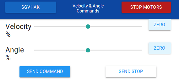
Once an abstraction layer was defined for communication between user interface and rover chassis calculations, I could start trying out various ideas for building a rover driving UI. The baseline rover UI presents two touchscreen controls mimicking joysticks on a traditional remote control vehicle: one moves up/down for controlling forward/back movement, and the other moves left/right for controlling steering. Driving the baseline rover using its UI is a two-thumb affair.

That is a perfectly valid and functional UI, but my ambitions grew beyond copying it. I wanted to explore ideas around single-finger operation. This decision held firm even after the person who created the UI for baseline rover warned us that it could be tricky to implement – single-point operation was already tried before going with the two-thumb approach. I may yet bow to their wisdom, but I wanted to give it a shot first!

Polar Pad

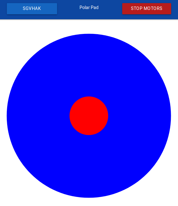
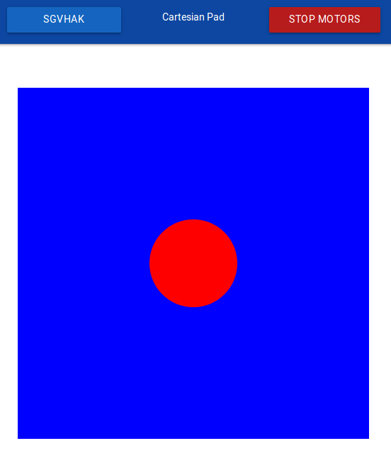
The first implementation of a one-finger driving control is based around polar coordinates. It seemed like an obvious match to rover mechanics: polar coordinates on a two-dimensional plane is an angle and a distance, which maps directly to rover control’s angle and velocity. The user puts their finger down on the red central control dot, and they can drag it around inside the blue circle to drive the rover. Move the dot up to drive forward, rotate the dot left to steer left, and so forth.

As I got into it, though, problems started to mount.

The first and most obvious problem is that our underlying infrastructure – HTML, <canvas> tag, and JavaScript input events – use cartesian coordinates. In order to implement polar coordinate control we need trigonometry math to convert between the two systems. Errors creep in as we perform multiple operations and conversions between coordinate spaces.

The second problem was a consequence of mapping upper semicircle to forward velocity and lower semicircle to moving backwards. This became problematic when the user wishes to steer at maximum angle.  Turning far left means moving straight left, but at that point small movements can flip between upper and lower semicircle, causing the rover to jerk suddenly between forward and backward movement.

To mitigate this, a band of dead space between the semicircles was introduced. The user is no longer able to use the full 180 degrees of a semicircle for movement, they are restricted to the middle 140 degrees with the far left 20 and far right 20 degrees blocked off. This was effective to prevent sudden transitions between full speed forward/backwards motion but it wasted screen real estate.

The third problem of polar coordinates was exposed when trying to maneuver the rover at low-speed around obstacles. When our finger is near the center of the circle, small left-right movement translates into large changes in steering angle. It was more difficult than it should be to make small steering changes at low speed.

The last problem is makes the above problem worse. When somebody runs into a problem, their first instinct is to lift their finger off the touchscreen. In order to retreat to a known safe condition, our control dot pops back to the center position representing wheels stopped and all steerable wheels pointing straight front-back. This is fine, but when people are frustrated by problem #3 of low-speed maneuverability, this behavior snapping to straight front-back erases whatever angle they were previously driving at, making low-speed maneuvers even more frustrating.

And what happens when a rover driver is trying to perform delicate maneuvers but find themselves fighting a bad UI that gets in the way and cause frustration? The rover ends up running into things and risk breaking gearboxes.

Now we have experimental evidence polar coordinate driving doesn’t work as originally thought, let’s take that lesson and create a new UI.


SGVHAK Rover Control Abstraction

Once we were confident our SGVHAK rover chassis control code looked pretty good, we were willing to trust that it could drive a rover without sending conflicting commands that make our rover try to twist itself into a pretzel. Now our focus turns to creating an interface for user control input.

A quick rough draft had been in place to help test rover chassis Ackermann math, letting a rover driver send a steering angle and travel speed to rover’s control code. But it was very tied to the current rover implementation: angle range was limited to angle range of what we have today, and speed was specified in raw quadrature pulses per second (QPPS) that we send straight down to RoboClaw motion controller‘s API.

Since we have ambitions for future rover variants, this direct dependency is not good. Future rovers may have a wider (or narrower) range of valid steering angles. They may also use something other than RoboClaw motor controllers. The answer is a typical software solution: abstraction!

This required changing the interface between our HTML UI front-end and the Flask-based Python code running on the rover. Instead of a fixed number angle or a fixed number of encoder pulses, user now send driving commands in terms of two percentages ranging from negative 100% to positive 100%.

For steering, -100% tells a rover to steer as far left as it could go, 0% is straight forward/back travel, and 100% is to steer as far right as it could go.

For velocity, -100% is travelling backwards as fast as it could, 0% is stop, and 100% is damn the torpedoes, full speed ahead.

Now when we adapt the code for future rover variants, we could focus on rover-side configuration and remain confident user-side HTML interface will automatically adapt to whatever capabilities are present on a particular rover variant.

This also allows us to experiment with user-side HTML without worrying about having to make matching changes in rover-side Python code. We can try different control schemes, as long as it ends up sending a velocity and steering angle percentage to the rover.

The first and crudest implementation of this concept is shown here: two HTML slider objects that move from -100% to 100%. The user can move the slider and tap “Send command” to rover. As the most basic HTML implementation possible, this is a useful test tool to isolate whether a particular control problem is in HTML front-end or in Python back-end, but it is obviously not a great driving interface.

That’s coming up next.

Velocity Angle

Visualizing SGVHAK Rover Chassis Calculations

When we were putting together code to calculate Ackermann steering angles for SGVHAK rover‘s wheels, initial testing was done via Python command line using some fixed test values to match against results pre-calculated by hand. Once we built some confidence our math was on the right track, it was time to start testing against more varied inputs.

There was just one minor problem – at this point in rover development, our software is a tiny bit ahead of the hardware which means we can’t test on hardware that hasn’t yet been assembled. Even if we could, it wouldn’t be a great idea to jump from a small fixed set of test values to actual hardware. As an intermediate step, we created a bit of code to visualize results of roverchass.py calculations: the “Chassis Configuration” screen will show what our control code thinks all six wheels should be doing. (This shows the intent, which is different from hardware telemetry of what’s actually happening.)

SGVHAK Rover Chassis Config

Each of the six wheels got its own blue box, laid out roughly analogous to their physical position on the rover chassis. Originally wheel steering & speed was displayed as text: number of degrees a wheel should be steered, and a second number reflecting the intended velocity for each wheel. This was accurate information but it took some effort to interpret. To make this information easier to understand, numerical text was changed to a visual representation.

By using HTML’s <canvas> element, we could draw some simple graphics. Each wheel is represented by a black rectangular outline. A wheel’s steering angle is now represented by tilting its rectangle to that angle. Inside a wheel’s rectangle is a green fill representing desired velocity. When a wheel is supposed to be stopped, there is no green fill and its black rectangle is empty. When a wheel is supposed to be rolling forward, green rectangle fills from the middle upwards. Faster velocity is represented by more green in the upper half. For a wheel that should be rolling backwards, green fills downwards instead.

This visualization of roverchassis.py calculation results were far easier for humans to understand. This made it very quick to validate that roverchassis is behaving roughly correctly. There’s a place for precise engineering calculations, but there’s also place for a quick glance to check “yeah, that looks about right.”

SGVHAK Rover Software: Chassis Calculations in Python

SGVHAK Rover Chassis ConfigOne of the biggest changes in our new rover controller code is the goal of managing all ten rover chassis motors together, starting to think of the rover as a single unit instead of ten individual things.

This logic is centered in roverchassis.py, which is be responsible for calculating Ackermann angles for all steerable wheels in the rover, as well as calculating the desired travel velocity for each wheel. In order to make this code as flexible as we can, we offload details of rover chassis into configuration files and make our Python math as generic as possible running calculations based on configuration file values. This meant we could support rovers with different geometries without editing source code. This feature began with a desire to have flexible wheelbase and track dimensions of our rover chassis, but eventually extended to supporting similar but different configurations such as two-wheel differential drive.

Another goal was to support different types of motors and motor controllers. We appreciated all the features in the RoboClaw motor controller we started with, but we also thought about trading off some of these features for lower cost. In preparation for this flexibility, we kept roverchassis.py focused on general Ackermann-related math and kept motor-specific code in a separate class. In the first draft, this meant pulling all RoboClaw related code into roboclaw_wrapper.py which translates general concepts from roverchassis.py into specific commands in Ion Motion Control’s public domain API roboclaw.py. Later on we validated this flexibility by steering a single wheel with a RC servo followed by adding support for LewanSoul serial bus servos.

This was all possible using a flexible syntax in config_roverchassis.json that allows us to adjust wheel dimensions as well as switch out individual wheel travel or steering motors for different motor controllers.