Obsolete Arduino Board Is Alive And Reading Analog Joystick

Learning Arduino has finally moved from a back burner to the front, and as a first step I finally unpackaged a years-old purchase of an Arduino Uno compatible board. Enough years have passed that particular board has become obsolete, but the Arduino ecosystem is still going strong so chances are good that I can still use the board to learn.

The first step with new hardware is always testing out some sort of a “Hello World” demo program to make sure the basics are working. When it comes to playing with electronics hardware, the popular choice is to blink a LED. This is such an entrenched thing that Arduino has designed a LED into their boards perfectly suited for the purpose, and my Arduino-compatible board has copied that arrangement.

Following the “Getting Started” guide for an Arduino Uno, I installed Arduino’s Desktop IDE. The basic example blink program was only a few clicks away, and an Arduino Uno was already selected as the target board type. Once I selected the serial port to use for communication, I was able to click on “Upload”. After a few seconds, I could see the test LED blinking on my board. It lives!

Success of that fundamental test gave me confidence to move on and add some hardware. I had bought some small joystick modules (*) for this purposes of building my own Arduino based controller. Like most joysticks, they are built around a pair of potentiometers which made them an easy match for Arduino joystick tutorial.

OSEPP Uno R3 Plus with joystick

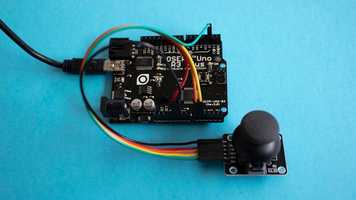
As many reviewers warned in that Amazon product listing, these joystick modules are very sensitive to movement. Their electrical range of motion is a surprisingly small subset of their actual physical range of motion. In other words, the potentiometers reach their minimum/maximum electrical values when the stick has only moved barely a third or halfway into its physical range of motion. This will be good for quick reaction movements but not as good for fine pitched movement.

These joysticks might not be the best ones for the job of rover control, but they will work well enough for continued Arduino exploration.


(*) Disclosure: As an Amazon Associate I earn from qualifying purchases.

Finally Opening My Arduino Compatible OSEPP Uno R3 Plus

With my newfound motivation to get rolling in Arduino programming, I am finally going to open up the plastic blister pack of my OSEPP Uno R3 Plus. I must have bought this item when it was on sale somewhere, thinking I would get into Arduino programming but ended up letting it sit on a shelf for years.

OSEPP Uno R3 Plus blister pack

Today the product web page lists it as a discontinued product whose production ended almost three years ago in June 2016. The packaging backside pointed buyers to the url www.osepp.com/boards which is not even a valid URL anymore and returns a HTTP404 error page instead.

OSEPP Uno R3 Plus specifications

If this had been a proprietary product I would have been worried if I could even use it anymore. But since it was based on Arduino, an open source product, I was not as worried. Based on its name and physical appearance I guess it was a derivative of the Arduino Uno, which is still an active part of the Arduino product line in Rev3 form.

OSEPP Uno R3 Plus PCB

The exterior dimensions of the circuit board look identical, as are the mounting holes, in order to be compatible with the Arduino shield ecosystem. Comparing it against the standard Arduino Uno I see a few modifications elevating this product above a mere clone. The power jack looks the same but the USB connector is different. Its reset button has been moved to make way for a connector labelled I2C. I see four surface mounted LEDs in the same place as the standard Arduino Uno, which will be useful as I recall the Arduino “Hello World” blinks one of them.

The only thing I’m not terribly thrilled about is the fact the processor is a surface mounted chip instead of socketed DIP of the standard Uno. A socketed chip would be easy to replace if I should damage it in some way, with this surface mounted chip I’m pretty confident I’d need to buy a new board.

I see a little bit of manufacturing residue on the circuit board, possibly solder flux that was not completely cleaned off. That and a few other cosmetic blemishes did not worry me in regard to board functionality. It looks ready to go, so let’s plug it in and see what happens.

I Found My Motivation To Enter World of Arduino: Make Sawppy Easier

When talking to people about fun electronics projects, it has come to people’s surprise that I have yet to do anything with an Arduino. It is the platform of choice for introduction to hardware computing and how many people got started in this hobby, but for one reason or another I never went through that phase.

Generally, if I need something with computing power or network connectivity, I use a Raspberry Pi 3. If I need low-level control over precision timing, I use a PIC. Sometimes those two are paired up, like our VFD driver board project. An Arduino’s capabilities fit in between those two platforms, but as I already have proficiency in coding for a Pi and for a PIC, it doesn’t leave much motivation for me to learn Arduino. But it’s something I kept in mind, expecting that one day an Arduino’s beginner friendliness will be an asset for me to build a project with one.

That opportunity has surfaced!

backyard sawppy 1600

As I took Sawppy around to various events, I had many opportunities to talk with people who show interest in a DIY motorized Mars rover model. My own personal ambition is to make Sawppy autonomous, but not everyone shares that goal. I learned that many people would be content with a remote controlled rover. Furthermore, I’ve seen a lot of interest in parents who wanted to gauge if Sawppy is a good project to build with their children. And in this scenario, my SGVHAK rover software running on a Raspberry Pi is far more complex than strictly necessary.

For this audience, a simple Arduino-based rover control system would fit a niche separate from that of a Raspberry Pi rover control scheme. It will be less powerful, but will also be lower cost and more approachable as a learning exercise for beginners.

So for the sake of making Sawppy more accessible to everyone, I’m going to start investigation into an Arduino-based control scheme.

Google AIY System Image Still Fragile

After exploring a Google AIY Voice kit’s capabilities and found it promising for future projects, I thought it was a pretty good deal at the clearance price of $15. Sadly for Google and Target, I still think its original price of $50 is high for what we get in the box. And that’s before I ran into what appears to be a recurring problem with the Google AIY kits: their customized build of Raspbian is very fragile and has a history of failing after system updates.

Google AIY Voice Bonnet

Of course, I didn’t realize the root cause immediately. When I initially booted up my box, with USB keyboard+mouse and HDMI cable attached, I ran through its initial setup procedure which helped me log on to my local network, change the default password to something other than ‘raspberry’, tasks of those nature. One of these steps was whether I wanted to download and install updates. Even though I followed instructions to download the latest system image, as of right now the “latest” is still from this past November and missing quite a few security patches since. I had continued playing with the hardware while updates installed, fiddling with things as I went. Eventually I had to reboot the box and when it came back up, everything has fallen apart.

I was in the middle of playing with aplay and arecord so my first symptom was a complaint of missing sound hardware. Since by then I had already established that they are standard Linux sound devices under ALSA (Advanced Linux Sound Architecture) I started looking up resources online to debug ALSA sound hardware running on a Raspberry Pi. This, I have since found out, is a huge bag of hurt best summarized by the following passage from this StackExchange thread:

However, at no time in history has mankind produced such an amount of useless and dysfunctional diagrams, as for trying to explain ALSA.

That’s just one man’s opinion, of course, but after several hours of banging my head against ALSA brick walls I saw nothing to contradict that opinion. Even Adafruit, typically the benchmark of clear concise tutorials, could only offer this mess which falls far short of their typical standards.

I was almost ready to give up on the whole works when I remembered to run a LED test and found that also failed with an error message Leds are not available on this board. That’s when I finally realized it’s not just the sound hardware, everything on board Voice Bonnet has gone offline. I’m not enough of a Linux expert to understand the details of what went wrong, but apparently certain types of system upgrades would wipe out all the customization required to support Voice Bonnet hardware.

This comment on a Github issues discussion thread suggested running a whole bunch of sudo dpkg-reconfigure commands to bring them all back. This might be worth trying some point later. But for today’s experimentation I re-imaged my microSD card and set up the box again – this time declining to download and install all updates. It’s a very insecure workaround, but today I only need to continue experimenting with the hardware. I’ll have to see if this problem is updated when I want to use this hardware for an actual project.

Bottom line: it’s very disappointing to have Google’s custom AIY version of Raspbian stop working on Google AIY hardware after certain system updates. I’m sure some number of these incidents resulted in the product getting returned to Target under their generous refund policy, which wouldn’t be very helpful to retail success at all.

Examining Google AIY Voice Bonnet LED and Pins

The default demo for a Google AIY Voice kit turns a Raspberry Pi Zero in a cardboard box into a Google Voice Assistant. I wasn’t terribly interested in that at full price, but at clearance discount they were interesting enough to purchase. I had fun looking over its “Voice Bonnet” audio accessory board to verify it is easy to re-purpose to sound-based projects of my own choosing. Once that primary goal was complete, I looked at some of the auxiliary features on that accessory board to see what’s going on.

Google AIY Voice Bonnet

First up is aiy.board which interfaces with the big plastic button. It looks like the kind of button found on an arcade console and I would expect it to be durable for many cycles. The source file has all the code dealing with the messy realities of dealing with a physical button, including logic to handle debouncing.

Next is aiy.leds. When assembling that button, I noticed it had more pins than strictly necessary for a button and it turns out the button also incorporates a RGB LED array. While aiy.board has code to deal with that LED array, comments indicate there’s a better API available elsewhere for the RGB LED in the aiy.leds source file. Indeed there appears to be better support for lighting effects like blinking, pulsing, and color blending.

Finally aiy.pins allows access to the GPIO pins exposed by Voice Bonnet. I had originally thought these were passed through from the Raspberry Pi GPIO bins, but further reading indicates I was wrong. These pins are controlled by the SAM D microcontroller on board the bonnet, and aiy.pins expose them for use in a way compatible with Raspberry Pi’s gpiozero library.

This looks like a pretty decent set of auxiliary functionality available on the Voice Bonnet, certainly enough to handle some simple projects without pulling in additional hardware. Also, the RGB button and auxiliary pins are apparently shared between the Voice and Vision bonnets so common code can drive both. This may prove useful somewhere down the line.

Google AIY Voice Bonnet Will Be Easy To Repurpose

Google’s AIY products were an experiment to bring a hands-on building experience to retail storefronts. It’s the kind of thing one would expect to find at Radio Shack, if Radio Shack were still alive. Sadly, with the AIY Voice kit marked down for clearance at my local Target, the experiment did not appear to be a resounding success. Still it means I now have a Google AIY voice kit to play with.

Just for the sake of seeing how it was supposed to come together, I followed assembly instructions even though I had no interest in building my own Google voice assistant for my home. Or at least, I got it set up far enough to have the mechanical box on my home network. I stopped before completing the steps to sign up for Google Assistant API access and enrolling this piece of hardware.

What it means is that I now have a Raspberry Pi Zero on my home network, coupled with “Voice Bonnet” audio hardware that I can now learn more about.

Google AIY Voice Bonnet

It appears all the code to interface with this Voice Bonnet is documented and available online. I went straight to the aiy.voice.audio APIs to see how one interacts with the audio capabilities. I had expected to find code interfacing with device drivers and hardware registers, I didn’t expect that the source file mostly consists of code that calls out to standard command-line audio utilities arecord and aplay.

I then looked into the default text-to-speech capabilities inside aiy.voice.tts and found much of the same: text is sent out to a command-line utility pico2wave which does all the hard work. It generates a sound file, which is then sent to aplay for playback.

This is great news: this meant it will be trivial to use the audio recording and playback capabilities of this Voice Bonnet for purposes other than interacting with Google voice assistant platform.

A Close-Up Look At VFD Internals

When we first pulled the vacuum fluorescent display (VFD) from an old Canon tuner timer unit, we can see a lot of intricate details inside the sealed glass. We had work to do that day – probing the pinout and such, but part of its overall allure comes from the beauty of details visible within. It is still something of interest, I just had to remember to bring my camera with a close up macro lens to take a few photos.

VFD under macro lens off

One of the reasons a VFD is so interesting to look at is the fact the actual illuminating elements sits under other parts which contribute to the process. Closest to the camera are the heating filaments, visible as four horizontal wires. This is where electrons begin their journey to trigger fluorescence.

Between these filaments and individual illuminating segments are our control grids, visible literally as a very fine mesh grid mostly – but not entirely – built on a pattern of hexagons.

And beyond the control grids, our individual phosphor coated segments that we control to illuminate at our command using our prototype driver board. (Once it is fully debugged, at least.) These phosphor elements are what actually emits light and become visible to the user. The grid and filament are thin which helps them block as little of this light as possible.

Fortunately an illuminated VFD segment emits plenty of light to make it through the fine mesh of grids and fine wires of filament. From a distance those fine elements aren’t even visible, but up close they provide a sophisticated look that can’t be matched by the simplicity of a modern segmented LED unit.

VFD under macro lens on

Salvaged VFD Power Supply And Debugging

Our first system integration test of a salvaged vacuum fluorescent display (VFD) and our prototype driver PCB was a success. At least going by our initial target of having our VFD segments illuminated and cycling through a test pattern to verify things are not stuck always on or off.

Once we had that basic level of functionality, [Emily] started working on the power supply side of the system. We have an original transformer salvaged from the same device which outputs multiple AC voltages. The first is a 2.5V AC line we could use directly on VFD filament. After that, Emily salvaged a few more components to deliver the ~30V DC we need for control grid and segments, and the ~24V DC we fed into a MP1584 buck converter to get 5V DC for filament bias and micro controller logic power.

VFD on transformer

We’re very close to a complete power solution for a VFD project, but not quite there yet. When we added a Raspberry Pi 3 to the mix, its power demand was too high for this system to handle. Power sagged to 4.2V and the Pi entered a power brown-out reset loop. We’re not sure what’s wrong with this setup yet, but in the meantime we connected an alternate 5V DC power source to look at how the rest of the system behaves.

This allowed us to see a problem in our prototype driver board. I had a new test pattern generated with the help of my tool created in Google Sheets, but the test program did not display as I expected. After some time sending various diagnostic patterns to the VFD, we figured out the key to the situation is segment H.

NEC VSL0010-A VFD Annotated

Whenever segment H is illuminated, everything else functioned as expected. But if segment H is dark, segments A-G are all dark regardless of commanded pattern. Segment I and J are unaffected.

Once this was determined, we ran a test pattern where H is commanded to be dark and everything else should illuminate. The test pattern is the same for every segment, so the circuit would be at a steady state for us to probe with a meter as the PIC cycled through segments.

Using segment A as an example, we probed to verify its output pin from PIC (RC0) is low as expected. We then traced that signal to the ULN2003, whose corresponding input pin is low as expected. With input low, the corresponding ULN2003 output pin should not be tied to ground. Which means we expect VFD pin for segment A to be sitting at near 30V DC due to a pull-up resistor.

This is where we went off script, for VFD pin A has been pulled low. Unplugging the wire between ULN2003 and VFD allowed the segment to illuminate. This narrows down the scope of our problem: it has something to do with that ULN2003 chip, but we ran out of time for tonight’s SGVHAK session before we could narrow it down any further.

To be continued!

Hello Google AIY Voice Kit

As someone who have played with electronics modules purchased online for a wide variety of projects, I was fascinated by Google’s AIY projects a.k.a do it yourself artificial intelligence line of products. Here in the United States, Google is not doing it alone. The products themselves are not enough if it isn’t in front of people’s faces, so there was also a partnership with the retail giant Target to have these kits on the shelves of Target stores. I didn’t think there is large enough of a market for these products willing to pay the prices it would take to justify a retail presence, but I admire the willingness to put up the money for an experiment to find out.

There were two kits: the AIY Voice kit and the AIY Vision kit. The vision kit costs roughly double that of the voice kit ($90 vs. $50) but it was far more interesting with an onboard Pi camera and a TensorFlow processor designed to accelerate machine vision tasks. When the vision kit became available at my local Target, I immediately purchased one so I could play around with its default demo software. Sadly my TensorFlow knowledge is still too weak for me to make the vision kit do my own bidding.

As for the voice kit, I knew it was also built around a Raspberry Pi Zero with a hardware accessory board, but that board was focused on audio capture and playback not significantly different from a sound card. I was not aware of any audio processing capability on board, so I expected the audio to be recorded and uploaded to Google for processing. This capability was not interesting enough for me to buy one at $50.

It’s been over a year since the retail experiment began, and my local Target has marked the AIY Voice kit for clearance sale at $15 each. (I later found out Micro Center was even more aggressively clearing them out at $5 each.) I guess this means we have an answer to that experiment. I’m a little sad to learn of this, because I would have loved to be proven wrong. If there was indeed a market for a successful product in this area that would have meant more interesting products for me to purchase locally. Alas, it looks like I’ll continue to buy esoteric little electronics gadgets online.

Still, right now I could pick up an AIY Voice kit for $15. The Raspberry Pi Zero at the heart of the device has a retail value of roughly $10 all by itself. Add in the microSD card and we’re pretty close to $15 before considering the rest of the kit. I passed on the AIY Voice kit at $50, but I’m willing to buy them at $15. Worst case scenario, I will have a Raspberry Pi Zero W and matching microSD card.

Here’s what I saw when I opened the box:

Google AIY Voice Kit

There were no surprises. Aside from the expected Raspberry Pi Zero W and microSD card, we have the hardware accessory called a “Voice Bonnet”.

Google AIY Voice Bonnet

The remaining hardware components are a single speaker and a big button (that turned out to have LEDs in it) and they plug into this bonnet.

Let’s see what this kit has to offer.

Adafruit Spooky Eyes On Raspberry Pi

[Emily] and I were first exposed to Adafruit’s “Spooky Eyes” in the context of their HalloWing given out to all Superconference 2018 attendees. We think it looks like a lot of fun and thought it would be nice to make it available on other hardware platforms. We looked under the hood to see how it has been packed tightly for low power microcontrollers, but as a result of its simplicity it was a fairly simple task to translate encoded Spooky Eyes data into PNG image files. This would make the image data more easily usable on less constrained hardware like a Raspberry Pi.

But as it turned out, Adafruit was way ahead of us. They already offer Spooky Eyes running on a Raspbbery Pi! I thought I had looked for this earlier but if so I had missed it.

Adafruit Raspberry Pi Eyes

Reading the details of that tutorial, a few interesting items of note:

  • Just like the HalloWing, there’s provision for light reactivity. However, a HalloWing has an onboard light sensor but a Raspberry Pi does not. The user would have to install a photocell.
  • By default the eyes move randomly, but there’s also provision for a joystick to steer their gaze direction. Again this is an analog joystick the user would have to install.
  • By default the eyes blink at random intervals, but there’s also the option to add buttons to trigger eyelid blinks.
  • Even though the product image shows a Raspberry Pi zero, the documentation says A Raspberry Pi 3 or Pi 2 is highly recommended. The code will run on a Pi Zero or other single-core Raspberry Pi boards, but performance lags greatly.
  • It is designed for Adafruit’s little display units, but the code could just as happily render to a Raspberry Pi’s standard HDMI output. Bypassing all the Adafruit hardware is possible as described in the Using Just the Software section.

Browsing through the source code repository, I see it uses quite a few Raspberry Pi specific code libraries. In addition code dealing interfacing the Adafruit display units, there’s also GPIO code to handle the joysticks and buttons above. And lastly, rendering is handled by the pi3d library to take advantage of a Raspberry Pi’s GPU. If I wanted to make Spooky Eyes run on, say, my Linux laptop, all those pieces of code would require modification.

Create VFD Bit Pattern With Help Of Google Sheets

With a successful integration test of our salvaged vacuum fluorescent display (VFD) we proceed to a few other tasks. On the hardware side, we’ll need to simplify our power supply situation. Our test had three separate AC plugs, we only really need one. We’ll also need to transfer what’s on the breadboard to a prototype circuit board.

On the software side, things are less clear because we’re still coming up with ideas on what to do with a salvaged VFD. Our very simple PIC driver code merely controls a pattern of bits, each bit representing a segment to be illuminated. This gives us a lot of flexibility but so far these bit patterns have been created using pencil and paper and quite time consuming. Once we have a project in mind we can write code specific to a theme, but until then it’s wide-open bits.

Well, at least we can streamline the pencil and paper system somewhat. The logic is not difficult, just time consume, and should be easy to automate. I started by creating a HTML form and laying out checkbox controls. I got as far as designing a JavaScript structure for checkbox click events when I realized everything is on a grid and looks a lot like a spreadsheet.

That realization led me to put my basic HTML and JavaScript on hold and switch to investigate what I can do in Google Sheets. The key that made it all possible is the BINTOHEX() function that reads a number, interpret it as binary, and translate to hexadecimal. This is the core functionality for my pattern generation and I was able to build everything else around it.

Here’s the initial build, with a fully populated grid of checkboxes and a test pattern for me to verify things were working.

VFD Pattern tool - full checkboxes

Once verified, I deleted the checkboxes that didn’t have a corresponding segment. This array now properly corresponds to our specific VFD.

VFD Pattern tool - customized checkboxes

Now creating a bit pattern is as simple as checking on the segments I wish to have illuminated. Here’s the pattern for “12:00”, the canonical Hello World for a time-based VFD display.

VFD Pattern tool - 12.00

I thought it would be fun to make this available for anyone to play with, but that requires keeping the sheet and its formulas fixed while allowing people to check and uncheck boxes. Unfortunately “view only” sharing does not allow checkbox manipulation, and “editable” sharing also allows modifying the sheet formula. Until I figure out how to do what I want, it was shared as “View Only” to the general public.


Integration of Salvaged VFD and Prototype Driver PCB

The time has finally come to put our salvaged vacuum fluorescent display (VFD) together with the prototype driver printed circuit board (PCB) we built for it. First we gave our VFD a little layer of protection. The individual pins of the VFD are small and seemed rather fragile. And as they went into a vacuum sealed chamber we had no means to repair, if one pin should break that would mark the end of our fun.

Fortunately, when we salvaged it from its previous home we noticed that those pins were quite strong in union. A single pin is fragile, but all twenty pins together was pretty strong. So we’ll solder up one of our cheap prototype boards to these pins just for the sake of holding them together. It was a bit tedious getting all the pins to line up. Two more boards were used as spacers to give us the desired distance.

VFD pin alignment

Once lined up, the VFD was soldered in place.

VFD pins in perf board

As anticipated, the assembly is now much more robust. Now we can work with this module with a lot less trepidation: if we should break a pin now, the break should stop at this PCB where we could still recover, not break all the way to VFD glass where we couldn’t.

We still had a lot of usable pin length remaining, so we left this unionizing PCB alone and soldered another one where we’ll actually attach wires and headers.

VFD second PCB

While this soldering work was underway, a breadboard was populated to test our design for interfacing our driver PCB and the VFD. Each VFD grid and segment wire received a 10 kilo-ohm pull-up resistor to the 30V line, and path cords were installed to map pins from our generic driver board to this specific VFD as per the pinout diagram we drew up earlier. Now the VFD, with its new more robust pins, should plug right in.

VFD interface breadboard

Finally, power delivery which is far more complex than what a LED project requires. This initial integration test had three different power sources. The power transformer we salvaged alongside this VFD delivers (among other voltages) the ~2.5V AC we need for our filament. With a few rectifier circuits, it should be able to deliver the other DC voltages we need as well, but we weren’t going to worry about it until we got this test working. In the meantime, a HP inkjet printer power supply delivered the 30V DC for grids and segments, and a Raspberry Pi delivers the 5V logic power as well as I²C control signals.

VFD integration test rig

We plugged everything in and… it lives again under our control!

Prototype VFD Driver Tested With Placeholder LED

PIC16F18345 VFD driver PCB

Once I had assembled our first prototype vacuum fluorescent display (VFD) driver circuit board, it’s tempting to connect it right up to our salvaged VFD and bask in its glow. But that would have been premature: there were bugs still to be ironed out with potential for fatal errors to damage or destroy our one and only salvaged VFD.

The first tests were what we used to test our bread board prototype: drive a 4-digit 7-segment LED, a Lite-On LTC4627-JR from my earlier PIC display driver project. From there I could verify 8 of 11 segments on this driver board functioned as expected by a demo program that constantly flips between two patterns, one spells “Hello” and the other “Ahoy”.

I then tested the I²C capability with a small update, changing the second pattern from “Anoy” to a very mutilated “MLE”. (It’s hard to do “M” on 7 segments.)

These experiments exposed a few minor bugs, just as tests were supposed to. After they were fixed I expanded my test with a second LTC4627-JR for eight total segments. I also expanded my use of I²C by continuously updating all digits from Raspberry Pi to create a text marquee. This experiment exposed some timing issues that is visible as a slight lag just as the “u” in “thank you” came up on screen.

That lag was diagnosed to my code inside a timer interrupt service routine (ISR). On a simple chip like this PIC, a hardware interrupt signal could not interrupt another ISR already in progress. So when my code inside a timer ISR grew beyond a certain point, it started interfering with timely response to hardware interrupts necessary for I²C communication. The solution is to put my timer ISR on a severe diet, moving almost all of its bulk elsewhere so that I²C handlers could run with minimal interference.

Once the software problems were sorted out, I started experimenting with the flexibility given by this project’s design decision to keep PIC code simple. It meant I could play with patterns that have nothing to do with displaying letters or text. I decided to try a pattern that keeps a single lighted segment running through the display in a figure 8. When cycled through all digits like a text marquee, it gave us a neat looking wave. I look forward to more experiments in driving a multi-segmented display in unusual ways.

Assembling Prototype VFD Driver PCB

PIC16F18345 VFD driver PCBIn addition to exploring the idea of aggressively packing chips densely, there were a few other design considerations in building our prototype driver PCB.

Why I²C?

When I was tearing my hair out trying to figure out why a tried-and-true piece of template code has stopped working, I was sorely tempted to move to some communication protocol other than I²C… good old TTL Serial always looks good whenever I run into a problem.

The answer is voltage compatibility: I want my driver board to be capable of running at either 3.3V or 5V, which is easy to do with an old 8-bit chip like the PIC16F18345 I’m using: give it power anywhere in its specified range (and probably a bit beyond that range) and it’ll happy run. But this doesn’t necessarily apply to whatever my driver board will accept commands from. Fortunately, I²C was designed from the start to accommodate devices that work off different VCC levels. So something like a Raspberry Pi (3.3V) can communicate with my PIC. (5V).

Pin Assignments

In addition to moving the decoder output pins so it could be placed immediately adjacent to my PIC, I also took advantage of my particular PIC’s feature of Peripheral Pin Select (PPS) by moving the I²C pins (handled by Master Synchronous Serial Peripheral – MSSP) from their default to RA4 & RA5 for easier routing on the PCB and easier data writes in my code.

Pin Isolation

This is the first time I planned to use pins RA0 and RA1 on a PIC16F18345 project. I usually avoid them because they are used as in-circuit system programming data (ICSPDAT) and clock (ICSPCLK) pins. They’re perfectly usable outside of this scenario, but they must be disconnected from the rest of the circuit during programming. In this case, it meant I had to put in two jumpers that are removed during programming. The jumpers are installed exactly where my PICkit 3 programmer would attach, so there’s no way for me to forget to remove them when reprogramming this chip.

Wires From CAT-5E Network Cable

Even with all these concessions to easier routing on a prototype PCB, there will still be an unavoidable nest of wires. In order to keep things tamed, I harvest my spool of CAT-5E network cable for wires that are thin and rigid. Thin wires help me fit more wires in a small volume, and rigid wires stay where I’ve put them. In addition to being affordable and easily available, the four twisted pairs of wires give me eight different insulation colors to help me keep track of which wire goes where.

Chip Packing Experiment On Prototype VFD Driver PCB

While we were building a breadboard prototype for our VFD driver, we weren’t terribly concerned with chip layout as it was largely constrained by the practicalities of a bread board anyway. Once we start thinking about transferring it to a PCB, however, we had more flexibility to be creative. The prototype printed circuit board is a grid of through-holes that we can use in any way we like. How shall we abuse this power?

While looking at how wires were run on our bread board, I noticed that there were a few pins that were perfectly aligned from one chip to the next. Placing the decoder output on PIC pins RB4, RB5, and RB6 lines them up perfectly with the input pins of 74138 decoder. As for the decoder output, six out of eight pins were directly lined up with a ULN2003.

Chip pin alignment

This allows some fairly straightforward wiring solder as these wires will not cross over each other and won’t tangle up and make a big mess. By itself that is valuable, but we were tempted to go one step further: how about we eliminate the wires entirely and jam those chips together? If they share the same PCB through-hole, that would eliminate wire soldering entirely.

It sounded good in theory, but in practice the chips are just a little too large for us to fit them three-abreast. I could push my decoder up against my PIC, but couldn’t push the Darlington array alongside the decoder as well. This is probably for the best – there’s value in having the ULN2003 lined up with its siblings.

Chips tightly packed on PCB

We may learn in the near future why this is a bad idea, but it’s all part of the fun: trying things and seeing how they work. (Or not, as the case may be.)

Breadboard Prototype of VFD Driver Project

Once we had some idea of what we wanted to do, it’s time to start wiring things up on a breadboard to see if it actually does anything interesting. Dealing with actual chips meant reading their data sheets and figure out where the rubber meets the road and how well theory meets practice.

Not having a lot of first-hand experience with such modules, it was a great way to learn by doing. The first surprise was behavior of the 74HC138 decoder module: Conceptually it takes a three-bit input and decodes it to one of eight pins. Conceptually we thought that meant raising one of eight pins high, but it actually lowers one of eight pins low.

We thought this was going to be a problem and started looking into inverters… before we realized it is a perfect pairing with ULN2003 to do what we actually wanted: The ULN2003 line inverts its input in the sense that when an input pin is high it connects the output pin to ground. So the output of a 74HC138 decoder (seven pins high, one pin low) driving ULN2003 results in seven pins connected to ground and one floating. We can work with this.

A 4-digit, 7-segment LED module stood in for the vacuum fluorescent display while all the logic got worked out. This flexibility is exactly where a breadboard is strong, letting us experiment and verify pieces of our circuit piecemeal. But it is not great for looking respectable or for long-term reliability, so once it successfully ran the LED module, we start planning to commit the design to soldering parts on a prototype PCB.

PIC16F18345 VFD breadboard and PCB

Hardware Side of Keeping PIC Driver Simple

For the VFD driver project, there were software design motivations to keep things simple. But that’s not the whole picture, there were also motivation from hardware constraints too. My previous projects to make a PIC drive a multi-segmented LED display had fairly simple wiring that connected most output pins of my PIC to current-limiting resistors. A few of the lines could have seen current flow higher than what a PIC is capable of handling, and those were handled with simple transistors. I knew there existed chips designed specifically to drive LEDs, but I wanted to learn the principles of controlling one myself.

Building something to drive a VFD requires dealing with voltages different and sometimes far higher than what is required to drive LED display modules. During our probe of this specific VFD we saw 2.5V AC and 30V DC, atypical of logic circuits. And just as there existed dedicated LED driver chips, there exist chips specifically designed to drive VFD modules, but again the project goal was to learn by building one ourselves.

So we turn to our standard electronic hobbyist toolbox item for controlling power and voltage beyond what our standard parts can handle: the ULN2003A line of Darlington arrays. The go-to solution for controlling inductive loads like relays and small motors, it can handle voltages up to 50V which we need for a VFD.

And again, with multiple different display projects on the horizon, it didn’t make sense to create a controller with hardware pinout specifically tailored to a specific unit. To keep things simple and consistent across displays, all of our controller outputs will be either left floating or tied to ground. If a particular device desires a particular pin to be at a higher voltage, we’ll have to wire up a pull-up resistor on that device’s specific interface board. We will learn if this concession to consistency will cause problems down the line.

VFD driver schematic

Why And How Of Simpler PIC Display Driver

Earlier in my outline for starting a new PIC display driver project for a vacuum fluorescent display (VFD), I mentioned one objective was to “keep the PIC side very simple and move more display-specific logic into driving code“. Let’s go into more detail on that part of the plan.

In my previous PIC display projects, the code was written for a specific multi-segment display unit as part of the overall project. This meant the source code reflected whether the LED was a common-anode or common-cathode design, it also knew about which segment represented which parts of a particular digit. This knowledge was required because I put priority on making control communication interface easy. For the temperature demo, making my display unit show “72.3F” was a matter of sending the actual UTF-8 text string “72.3F” as bytes. The PIC then parsed that string and determined which segment to illuminate.

But there’s a good chance we have several other matrix display projects in the future, and I didn’t want to invest the time to hard code intricacies of each unit into the PIC. It would be much easier to adapt and experiment if such logic was moved to a more developer-friendly environment like Python on a Raspberry Pi. In the case of the current NEC VFD under consideration, there are segments corresponding to days of the week and other function specific segments like an “On and “Off” text, “OTR”, little clock icon, etc. Most of which won’t necessarily be present on another VFD unit, why spend the time to embed such knowledge in my PIC driver?

NEC VSL0010-A VFD Annotated

We also want the flexibility to explore using the display in ways that are far afield of its original intent. For starters, that seven-segment display in the center doesn’t have to be constrained to display numbers for a clock. All these desires meant moving away from performing data interpretation on the PIC.

Instead, the PIC will accept a raw data stream where each bit corresponds to whether a segment is on or off. Each byte will correspond to 8 segments in a grid, and so forth. This means the task of mapping a desired digit to a set of segments will be the responsibility of driver code on host device rather than PIC peripheral. PIC will only concern itself with rapidly cycling through the matrix of digits keeping them all illuminated.

Old Microchip MCC Boilerplate for MSSP Requires C90 Compatibility Mode

PIC16F18345 VFD driver PCB

I’ve figured out how to compile the new Microchip Foundation Services Library boilerplate code for implement I²C peripheral, only to learn it doesn’t do what I wanted it to do. Well darn, it’s time to go back to the tried-and-true I²C boilerplate code I’ve used in earlier projects. It’s still there, it compiles with only the “this is outdated” warning, and I knew it worked well enough to be a good starting point for my projects. It was the tried-and-true known quantity that shouldn’t give me any trouble at all.

Except it did.

The code compiled fine, but it didn’t actually work. It would give a response to the first I²C query but then it would stop responding. Here’s the default boilerplate code, which responds to address 0x08, as probed by a Raspberry Pi using i2cdetect tool.

pi@raspberry:~ $ i2cdetect -y 1
     0  1  2  3  4  5  6  7  8  9  a  b  c  d  e  f
00:          -- -- -- -- -- 08 -- -- -- -- -- -- --
10: -- -- -- -- -- -- -- -- -- -- -- -- -- -- -- --
20: -- -- -- -- -- -- -- -- -- -- -- -- -- -- -- --
30: -- -- -- -- -- -- -- -- -- -- -- -- -- -- -- --
40: -- -- -- -- -- -- -- -- -- -- -- -- -- -- -- --
50: -- -- -- -- -- -- -- -- -- -- -- -- -- -- -- --
60: -- -- -- -- -- -- -- -- -- -- -- -- -- -- -- --
70: -- -- -- -- -- -- -- --

That part looks good, the problem comes when we run the same tool again.

pi@raspberry:~ $ i2cdetect -y 1
     0  1  2  3  4  5  6  7  8  9  a  b  c  d  e  f
00:          -- -- -- -- -- -- -- -- -- -- -- -- --
10: -- -- -- -- -- -- -- -- -- -- -- -- -- -- -- --
20: -- -- -- -- -- -- -- -- -- -- -- -- -- -- -- --
30: -- -- -- -- -- -- -- -- -- -- -- -- -- -- -- --
40: -- -- -- -- -- -- -- -- -- -- -- -- -- -- -- --
50: -- -- -- -- -- -- -- -- -- -- -- -- -- -- -- --
60: -- -- -- -- -- -- -- -- -- -- -- -- -- -- -- --
70: -- -- -- -- -- -- -- --

It has disappeared from scan, as it no longer responds to I²C commands sent to its address.

Comparing the I²C boilerplate code with my old LED project, I saw no differences worth mentioning. It should be the exact same code but it no longer does the exact same thing. What has changed between my old LED project and now?

Eventually I found the answer: Microchip has updated the XC8 compiler to C99, and this compiler update causes problems with existing code. I previously saw this in the form of compiler errors on an empty MCC-generated project. I no longer see compiler errors on an empty project template but arguably this is worse: no compiler errors but silent changes in behavior.

The solution is the same as before: change project properties so XC8 compiler uses its old C90 compatible mode. Once I switched over, the I²C boilerplate code functioned as expected.

Project Properties

Since Microchip has marked this old I²C boilerplate code as deprecated, I don’t expect them to bring it up to date with the new compiler. And given its history of causing me headaches, I guess I’ll plan on using C90 mode for all my projects for the foreseeable future.

Getting Microchip Foundation Services Library I2C Boilerplate To Compile

PIC16F18345 VFD driver PCBMotivated by the desire to get an old VFD up and running for fun, I set up my PIC16F18345 to act as an I²C peripheral. I could write my own code from scratch, or I could build on top of boilerplate code published by Microchip for implementing an I²C slave device. My problem is that I had two choices – the new thing that doesn’t compile, or the old thing that is deprecated.

I’ve since figured out how to resolve the two error messages to compile the new thing, formally called Foundation Services Library.

The first compiler error message was this:

In file included from mcc_generated_files/USBI2C_app.c:25:
mcc_generated_files/drivers/i2c_slave.h:55:34: error: unknown type name 'interruptHandler'
void i2c_slave_setReadIntHandler(interruptHandler handler);
^

Searching elsewhere in the generated boilerplate, I found a declaration for interruptHandler in another different header file. Copying it into i2c_slave.h addressed the “unknown type name” error.

typedef void (*interruptHandler)(void);

However, that error was replaced by a warning that there are now duplicate declarations of interruptHandler. This seems silly – if there were a declaration to collide with, it should not have thrown an unknown type name error signifying the declaration’s absence.

MPLAB should either not throw the error, or not raise the warning, but it is doing both. I have yet to figure out if the toolchain is busted or if the boilerplate code is. For now, though, I could proceed to the next problem.

The second compiler error message was this:

mcc_generated_files/USBI2C_app.c:30:14: error: no member named 'SSP1IE' in 'PIE3bits_t'
PIE3bits.SSP1IE = 1;
~~~~~~~~ ^
1 error generated.

This one was easier to figure out – go into the header files for this chip and look for SSP1IE. I found it declared on PIE1bits instead of PIE3bits. So to get this code to compile, I changed the boilerplate code from this:

void USBI2C_Initialize(void){
PIE3bits.SSP1IE = 1;
i2c_slave_open();
}

To this:

void USBI2C_Initialize(void){
PIE1bits.SSP1IE = 1;
i2c_slave_open();
}

What does PIE1bits.SSP1IE actually do? I’m not sure so I’m not positive this is actually the correct fix. But at least all of the foundation boilerplate compiles, and I start browsing through sample code for MikroElektronika USB-I2C Click module to figure out what it does and what I can do with it. Reading through code and comments, I saw this comment block.

- This module only supports byte operations. Block read and write operations is
not yet supported by MCC Foundation I2C Slave Drivers.

This comment implies Microchip has decided to deprecate their previous I²C library even though the new library is unable to duplicate important functionality. If true, this is… unsatisfactory. I want block read and write operations for my project.

Now I’m even more motivated to stay with the old code, but unfortunately there were some complications with that, too…