It’s always nice when the team behind a particular piece of software put in an effort to make newcomer introduction easy. Part of Angular’s low-friction introduction shopping app tutorial is letting us learn Angular basics without installing anything on our development machines, by using the web-based development environment StackBlitz. After I used it for the Angular tutorial, I took a quick detour to learn a bit more about StackBlitz to see what else it might be useful for.
According to the StackBlitz announcement post in 2017, its foundation is built from components of Visual Studio Code but transformed to be accessible via a browser. Behind the VSCode-based UI is a big pool of virtual machines spun up on-demand to support front-end web development. StackBlitz started with support for Angular and React, and more have been added since. Plus a beta program for full stack development so their ambition is still expanding. These virtual machines perform code compilation and also a web server to host the results. These servers are public by default, so developers can check how their results look on a cell phone, on a tablet, etc.
But while StackBlitz gives us online compute resources, their generosity does not extend to online storage. Their “tight GitHub integration” is another way of saying all our project code must be stored in our GitHub repositories. If a user is not willing to enter their GitHub credentials, their work only lasts until they disconnect and the virtual machines are shut down. Since I’m squeamish about spreading my GitHub credentials any more than I absolutely have to, this meant abandoning my Angular introductory app once it was complete.
That was the biggest damper on my enthusiasm for StackBlitz. If it weren’t for that bit of security paranoia, I would consider it a good replacement (at least, for the supported types of projects) for Cloud9 which used to be another free online development environment. Unfortunately, after Cloud9 was acquired by Amazon, using Cloud9 is no longer free. Even though Cloud9 is still very affordable in absolute terms (doing my LRWave project on Cloud9 only cost me $0.43 USD) there’s a huge psychological gap between $0.43 and free. Will StackBlitz lose its free usage in the future? Probably. Money to pay the bills for those virtual machines have to come from somewhere.
If this freebie goes away, so be it. It wouldn’t be the end of the world for the average Angular developer because the primary usage scenario is still centered around installing the tools on a development machine.
Wading into a new domain always means learning a new vocabulary as well. The first thing I read was Introduction to Angular Concepts, knowing full well not all of it would make sense until later. The most valuable thing it taught me is that certain generic-sounding words actually have specific meanings within an Angular context, which is an important lesson to learn while reading documentation. In this case, I have to be careful when coming across words like “modules”, “components”, and “services”.
Angular’s “Getting Started” section starts out with a “Try It” walk through building a sample Angular application. It is a mock shopping app with a product list, a shopping cart, and checkout UI. They do the usual web app things like creating forms (got to have those forms) and communicate over HTTP. Following along with this sample, I got to see the concepts of “components” and “services” put into practice. I’m still a little fuzzy on “modules”, though. I believe it is because modules don’t really come into their own until we have a much larger project. At which point it makes sense to group lots of components into modules, something that would not be necessary in a small sample tutorial.
I also got to see the good and bad sides of using TypeScript. The good news is that some mistakes will trigger compile-time errors for me to fix before proceeding. I find this a vast and compelling improvement over JavaScript standard operating procedure of watching things going awry at runtime and trying to debug what went wrong. The bad news is that it’ll take some experience before I can understand what those error messages are trying to tell me. Here’s one example of an error message that I found bewildering. It wasn’t immediately obvious to me that I used too many curly braces, three instead of two.
Template parse errors:
Parser Error: Missing expected : at column 9 in [ {{{product.name}}} ] in ng:///AppModule/ProductListComponent.html@3:6 ("

<div *ngFor="let product of products">
<h3>[ERROR ->]
{{{product.name}}}
</h3>
"): ng:///AppModule/ProductListComponent.html@3:6
Parser Error: Unexpected end of expression: {{{product.name}}} at the end of the expression [ {{{product.name}}} ]
Going through the exercise I learned that an Angular component typically associates the three parts of web development (HTML, CSS, JavaScript) into a functional unit. The JavaScript file defines the component class. The HTML is modified with Angular-specific annotations and called the component template. And the component style sheet was a pleasant surprise, since I had struggled with how to best organize my style sheet files in earlier projects. Hopefully Angular components will make it easier.
I felt it was an effective introduction, giving a quick tour of major components of Angular and giving me enough of a vague idea of what’s going on, enough to proceed further and learn more. But before I go deeper into Angular, a little detour to look at the infrastructure behind this “Try It” walkthrough.
I started thinking about doing another web technology project because I thought it might be good to have the option of building my own custom Node-RED Dashboard widgets. But during my research of study prerequisites I started reading about Angular. The more I read, the more I think it’s worth a closer look. I was enticed by the following:
It is a web technology of the SPA (single page application) era, moving more processing to the web browser and reducing load on the web server. Google has obvious incentive to reduce their server load, but it also means SPAs can be compiled down to static content and hosted on any web server. For hobbyist projects, this drops the minimum hardware requirement from a Raspberry Pi (to run something like Ruby on Rails) down to an ESP32 (static web server).
Angular is built on TypeScript, which adds compile-time type checking capabilities to JavaScript. Potentially eliminating a lot of JavaScript runtime failures that have frustrated me in the past.
Angular Materials is now my primary motivation, displacing Node-RED Dashboard. I’ve been fascinated by Google’s Material Design ever since the concept was launched. This is not a surprise to anyone who’ve seen my web technology projects. The SGVHAK rover UI was built on an early version of Materialize CSS. It gave me a Material Design look but with usage semantics somewhat resembling Bootstrap. My LRWave project was written using completely different set of tools, but it also picked up a Material Design style by the use of Material Design Components (MDC) for Web.
So the siren song call of Material Design has pulled me in yet again, this time to Angular and the promise of being able to build UI for projects that can be hosted anywhere… from static servers like an ESP32 or GitHub Pages, to full fledged web server running on a Raspberry Pi, to desktop applications via ElectronJS.
It all sounds very attractive for a tool to add to my toolbox, so I’ll start investing some time into learning Angular.
Digging into an obscure button was fun, but (sadly?) not the main focus of this blog, which is for me to write down notes about my projects and technology explorations. If anyone finds the information useful, that’s just icing on the cake.
This time around, getting back to “work” puts focus on software development. My learning experience with the Node-RED Dashboard taught me it was very easy to get a functional browser-based UI up and running giving users like myself a fantastic way to build out ideas. But with ease of use comes the usual trade-off of limited control. The people behind Node-RED Dashboard is aware of this, providing anyone who is unsatisfied with the default tools an entry point to add custom dashboard widgets. Unfortunately, the learning curve climbs sharply upwards for me since I have little experience with many of the underlying technologies. If I want to explore that world, I have to weigh the following points:
No experience with AngularJS (a.k.a Angular v1) which is the foundation of Node-RED Dashboard.
No experience with Angular (a.k.a. Angular v2+) which is an incompatible but currently-maintained replacement.
No experience with creating reusable JavaScript modules or the convention around creating packages.
Only basic skills with HTML, CSS, and JavaScript.
This list is sorted roughly in the order of most- to least-specific to my original motivation of creating custom Node-RED widgets. With such a list it usually makes the most sense to start at the top (focus on the motivating goal) or start at the bottom (build a solid foundation.)
For the purposes of foundation building, I’ve tackled a few HTML/CSS/JavaScript projects but nothing that really stuck with me for long term development. An early example was the web based UI for SGVHAK rover, which eventually became my default control scheme for Sawppy rover as well. Updating that UI has been on my to-do list ever since, and I have yet to get back to it. I later explored a different set of web development tools with my LRWave project, but again that had been set aside after v1.0 was complete. Given this track record, I’m not sure retreading the same grounds will give better results.
So what about the other side? Start with AngularJS? I was ready to do so because of Node-RED Dashboard, but most of my motivation evaporated when I learned AngularJS has been abandoned. If I want to learn something that’ll be useful beyond Node-RED dashboards, I should learn its successor Angular instead.
Yesterday I documented my quest to track down a button I saw on a prop used in the movie Sneakers which premiered 28 years ago. Eventually learning that they were Omron B3J-2100s, and they are still available for purchase from Digi-Key. Given the age of the movie, plus the fact this little detail was not important to the plot, plus the fact the rows of buttons were on screen for only roughly five seconds, I expected my blog post to quickly disappear into footnotes of the internet. Like everything else on this blog it was just a note from my personal explorations. Maybe it’ll receive an occasional a visitor, here to learn how to get these buttons for themselves.
Judging by web traffic, I was quite mistaken. I knew that the movie made impressions on others like myself, but I underestimated how many of us were out there. And even more surprisingly, these buttons made an impression on people as well. I had no idea there were so many button connoisseurs out there whose appreciation for a switch goes beyond whether it can reliable close and open a circuit. My blog post and associated Tweet were picked up by Adafruit blog and someone even submitted it to Hacker News where it was as high as #13 for a brief time. Amazing.
Its popularity also received feedback from many others. I found the prop in the movie was a Sequential Circuits Prophet 2002, but several people brought up the Roland TR-808 and there was also a mention of the Oberheim OB-X. They all used similar looking buttons for similar purposes: select options and an associated LED to indicates the active item. However, despite the similarity (and the TR-808 uses color to great effect) they are not the same Omron B3J buttons of a Prophet 2002.
I started posting a few corrections, but then I stopped. I realized that people were just sharing their own fond memories and there is no particular reason I have to point out they weren’t Omron B3Js. If someone is fond of a stylish button, what’s the point of taking away their joy? For the sake of pedantic correctness? Nah, we’re all connoisseurs of our own favorites. They have theirs, and I have Omron B3J.
Thanks to [garrettlarson] on Hacker News, we have a link to a YouTube clip where we can see the Prophet 2002 and its row of Omron B3J-2100s. (Go to ~1:20 if embedded time offset isn’t working.)
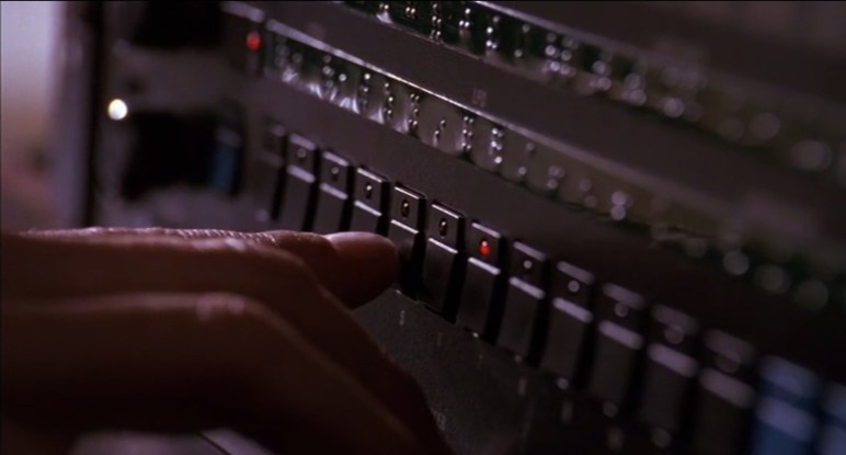
I’m a fan of physical, tactile buttons that provide visual feedback. I realize the current trend favors capacitive touch, but I love individual buttons I can find by feel. And one of the best looking buttons I’ve seen was from the 1992 movie Sneakers. When the blind character Whistler used a Braille-labeled device to add a sound effect representing the “thump” sound of a car going over seams of a concrete bridge.
They were only on screen for a few seconds, but I was enamored with the black buttons, each with a corresponding red LED. The aesthetics reminded me of 2001, like the eye of HAL in a mini monolith. Or maybe Darth Vader, if the Sith lord were a button. When I first watched the movie many years ago, I thought they were neat and left it at that. But in recent years I’ve started building electronics projects. So when I rewatched the movie recently and saw them again, I decided to research these buttons.
The first step is to determine if they were even a thing. All we saw was the front control panel of an unknown device. It was possible the buttons and LEDs were unrelated components sitting adjacent to each other on the circuit board, and only visually tied together by pieces of plastic custom-made for the device. So the first step was to find that device. There was a label at the bottom of the panel below Whistler’s hand, but due to the shallow depth of field I could only make out the end as “… 2002 digital sampler”. Time to hit the internet and see if anyone recognized the machine.
The first step is the Trivia section of the movie’s page on Internet Movie Database where people contribute random and minute pieces of information. Firearms enthusiasts can usually be counted on to name specific guns used in a film, and automotive enthusiasts frequently contribute make and model of cars as well.
Sadly, the electronics audio enthusiasts have not felt fit to contribute to this page, so I went elsewhere on the internet trying various keyword combinations of “Sneakers”, “Whistler”, “sampler”, etc. The answer was found in a comment to a Hackaday post about the movie. I’ve complained a lot about the general quality of internet comments, but this time one person’s nitpicking correction is my rare nugget of gold.
Whistler’s device is a Sequential Circuits Prophet 2002 Digital Sampler rack. As befitting the movie character, the sampler’s control panel had Braille labels covering the default text. But otherwise it appears relatively unmodified for the movie. I wish the pictures were higher resolution, but their arrangement strongly implies the button and LED are part of a single subcomponent. The strongest evidence came from the presence of four vertical axis buttons, rotated 90 degrees from the rest.
Aside: On the far right of the control panel, we can see a sign of the era, a 3.5″ floppy drive for data storage.
Encouraged by this find, I started searching for Prophet 2002 buttons. I quickly found an eBay community offering replacement parts for Sequential Circuits products including these buttons. What’s intriguing to me is that these are sold in “New” condition, not surplus or salvaged from old units. I’m optimistically interpreting this as a hint these buttons might still be in production, decades after the Prophet 2002 was released in 1985.
Thanks to those eBay listings, I have seen a picture of the component by itself and it is exactly what I hoped it would be: the button’s exterior surface, the electric switch itself, and the LED are integrated into a single through-hole component. Given the tantalizing possibility it is still in active production and something I can buy for my own projects, I went next to electronics supplier Digi-Key.
Digi-Key carries 305,212 components under its “Switches” section, not practical for individual manual review. Fortunately there are subsections and I first tried “Tactile Switches” (5721 items) because those buttons look like they’d give a good tactile response. In the movie we also heard a satisfying click when the button was pressed, but I don’t know if that was added later by the film’s sound mixer.
Within the “Tactile Switches” section, I aggressively filtered by the most optimistic wish they are active and in stock:
Part Status: Active
Stocking Options: In Stock
Illumination: Illuminated
Illuminator: LED, Red
That dropped it to 76 candidates. Almost all of them carried their illumination under the button instead of adjacent to it. The closest candidate is a JF Series switch by NKK Switches, the JF15RP3HC which has a Digi-Key part number 360-3284-ND.
It is a more modern and refined variant of the same concept. The button is sculpted, and the illuminated portion sits flush with the surroundings. This would be a great choice if I was updating the design, but I am chasing a specific aesthetic and this switch does not look like a monolith or Vader.
So that wasn’t too bad, but I’m not ready to stop. Peer to “Tactile Switches” are several other subsections worth investigating. I next went to “Pushbutton Switches” (175,722 items) and applied the following filters. Again starting with the optimistic wish they are active and in stock:
Part Status: Active
Stocking Options: In Stock
Type: Keyswitch, Illuminated
Illumination Type, Color: LED, Red
That filter cut the number of possibilities from 175,722 down to 21 which felt like an overly aggressive shot in the dark, and I expected I would have to adjust the search. But it wouldn’t hurt to take a quick look over those 21 and my eyes widened when I saw that list. Most of the 21 results had a very similar aesthetic and would make an acceptable substitute, but that would not be necessary because I saw the Omron B3J-2100.
Yes, I’ve hit the jackpot! Even if that isn’t precisely the correct replacement for a Prophet 2002 sampler, it has the right aesthetics: a dark angular block with the round LED poking out. But now that I’ve found the component, I can perform web searches with its name to confirm that others have also decided Omron B3J is the correct replacement.
Omron’s B3J datasheet showed a list of models, where we can see variations on this design. The button is available in multiple colors, including this black unit and the blue also used by the Prophet 2002. The number and color of LEDs add to the possible combinations, from no LEDs (a few blue examples on a Prophet 2002 have no lights) to two lights in combinations of red, green, or yellow.
Sure, these switches are more expensive than the lowest bidder options on Amazon. But the price premium is a small price to pay when I’m specifically seeking this specific aesthetic. When I want the look that started me on this little research project, only the Omron B3J-2100 will do. And yeah, I’m going to call them “Whistler buttons”.
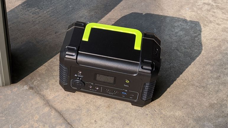
After a service life of over two and a half years, this Monoprice PowerCache 220 was retired due to its degraded battery and malfunctioning thermal protection system. I bought a Paxcess Rockman 200 to replace this old workhorse, which is now long out of warranty and has also been discontinued. Can I fix it? Should I fix it? I won’t know until I take it apart and see what I can find out.
The first step is removing side panels. They are held by hex-drive socket head fasteners that appear to be large durable machine bolts.
Once freed by a hex wrench, however, we see it was an illusion. Underneath the big beefy top is a short self-tapping screw fastened to the plastic. I don’t recall ever seeing a self-tapping fastener with a hex-drive socket head before today.
Once the tough-looking (but actually not) fasteners have been removed, the side panels could slide downwards roughly 1cm, then they can be freed.
With the sides removed, we’ll need to remove the rear fasteners. This is fairly straightforward, none are hiding behind labels. They are all self-tapping Philips screws in clearly visible recessed round holes.
Once those screws are removed, rear half of the enclosure can be lifted to expose the remaining attachment point: a wire harness for the cooling fan mounted in the rear enclosure.
It was easy to unplug the fan (looked like a JST-XH polarized connector) to get a clear look at the interior. Most of the available volume is allocated to a large sealed lead-acid battery. The battery is surrounded by a few pieces of foam padding, probably so it wouldn’t rattle around as the unit is carried around..
This PCB is dominated by large components we would expect to see in a power control application.
Attached to the aluminum heat sinks are power control MOSFETs.
The Golden Rule of Teardowns: Whenever an identifier is visible, put it into a web search to see what comes up. Unfortunately we’ve got nothing for SGD005-INV. In time, the search engines will find this page and send people here. I apologize in advance to those who come to this page seeking information I don’t have.
I was pleasantly surprised to see an easily replaceable fuse. It looks like a standard blade-style fuse popular in automotive applications. I feel it is on the lenient side as 35A * 12V = 420 Watts. I agree if this fuse blows, something has gone very very wrong, but I’m not convinced it’ll blow early enough to protect the rest of the device.
I had expected unpopulated debug points like the RX TX and GND visible towards the right, but the connection to the left actually had populated headers and that was a surprise.
I was encouraged by what I’ve seen so far. It all looks nice and tidy. If I can figure out the thermal problem, I should be able to restore this to full function with a new sealed lead-acid battery. Either way, the degraded battery needed to be removed. This was when I learned the foam padding was glued to the battery. I had hoped they could be easily transferred to a replacement battery, but sadly not.
Once the battery was removed it became much easier to move things around to get a better look. The temperature sensors are likely thermistors, and they have been held into a channel on the heat sink with some kind of glue that dried into a white blob. I had hoped maybe a sensor is misplaced, or dislodged, or unplugged, but it was none of those obvious problems. With those easy fixes ruled out, my prospect for repair dropped.
And once I flipped up the power PCB, my willingness to figure out the temperature problem also dropped. While one side was nice and tidy, the back side is a mess. I see lots of extra solder tinned to various areas on the circuit board, presumably to increase electric current capacity by some amount. And there’s some kind of white residue left all over the board presumably from soldering flux.
A quick web search found that this “heaps of solder” approach is not unusual for lowest-bidder circuit boards. Supposedly it is not terribly effective, but it does provide some benefit for nearly zero additional cost and thus sometimes chosen over any other “right way” approaches to solve the problem.
Not knowing the design constraints placed upon the engineers behind this product, I shouldn’t criticize. After all, it has worked well for over two and a half years. However, it doesn’t make me terribly fond of the device and given that the trivial fixes have been ruled out, repairing it has dropped very low on my priority list. Heck, let’s just say it has been removed from the priority list entirely.
Focus thus shifted from “evaluation for repair” to “satisfy curiosity and evaluate parts salvage.” Looking around the messy circuit board some more, I see the brains of the operation: the STM32F030K6 is a 32-bit ARM Cortex-M0 microcontroller, a cousin of the chip used in the “blue pill” development boards. Unsurprisingly, it is right next to the populated debug header pins I noticed earlier, though the traces don’t seem to go directly into the chip.
Looking past the power control PCB, I see another circuit board. Ah, yes, we would certainly need another board for the front panel status display, and on/off buttons.
Unplugging a few wiring harnesses gave us a better look.
The brains of this operation is a less powerful 8-bit chip, the STM8L052C6.
To give myself a little more room to work, all connectors to the power control PCB has been removed.
But it’s still too cramped, so I also removed the handle. This is a very sturdy handle that is also comfortable to hold. Attached with not just six screws but also molded-in channels to take up weight from the front and rear enclosure halves. Usually when I tear down retired products for salvage, the non recyclable plastic is sent to the landfill. But this time I’m looking at a sturdy enclosure with a handle and think there may be a second life for them.
Finally the control PCB is freed.
Not too many immediate candidates for salvage on the back side.
But the front is a different story. Multiple buttons and LEDs, plus four jacks. Two of them are common 5.5mm OD / 2.1mm ID barrel jacks, the other two are less common but matches the size used by Lenovo for some devices. Piezo buzzer, USB ports, all kinds of good stuff. I doubt I’ll find another use for the LCD panel, though.
I’m still very wary of 110V AC, but these sockets are so easy to salvage I might as well do so. I’m amused at the fact the grounding prong is left unconnected. A portable power source is not connected to ground, so of course there’s nothing to connect them to, but it’s still funny to see.
The 12V “cigarette lighter” socket is very likely to find another use. I wanted to salvage this connector but it was not obvious how. It took me a while to figure out what I was looking at, the answer is that the entire outer base is the “nut” holding the socket in place. In order to remove it from the panel, I had to turn the whole exterior counter-clockwise. And before I could do that, I had to break away most of the solidified orange adhesive.
Nonstandard size meant I had to dig through the tool box for pliers and vise grips of the right sizes to grip without crushing the thin metal exterior can. But eventually it was freed, and the socket could be removed from the panel.
Using earlier pictures as reference, I plugged all the electrical connectors back where they were. Then the mechanical components were laid out for this final roll call without the battery.
Out of all the electronics, I believe the cooling fan will be the first to find a use somewhere, followed by the 12V socket. But I’m actually more intrigued by the enclosure. It is sturdy, already designed to carry something heavy, has provision for cooling, has a big confidence-inspiring handle, and soft rubber feet cushions impact when I set down the box. I think I will cut away the front panel and replace it with something 3D-printed or laser-cut, and the rest of the… whatever it will be… can be installed inside the box. There are lots of potential here.
I had been using a Monoprice PowerCache 220 to store and use power generated by my small Harbor Freight solar array. Due to its degrading battery and erroneous thermal protection circuit, I bought a Paxcess Rockman 200(*) to replace it. Thanks to its lithium chemistry battery, the Paxcess is far smaller and lighter than the Monoprice unit it replaced. Which made a good first impression as something I noticed before I even opened the box.
Two means of charging were included with the Rockman 200, giving users two choices of power source. Either use an automotive “cigarette lighter” power socket adapter, or use a household AC voltage power adapter. But I intended to charge from solar power, so I had to fashion my own charging adapter. Fortunately the Rockman 200 used commodity barrel jacks (5.5mm outer diameter, 2.1mm inner diameter) so it was easy to build one from my most recent purchase(*) of such connectors. This was much easier than the hack I had to do for my Monoprice.
Once up and running I was indeed able to charge from my Harbor Freight solar array. The maximum no-load open circuit voltage of these panels were around 21V, lower than the 24V maximum input voltage limit of the Rockman 200. The Rockman 200 had a far more informative display than the very limited one on board Monoprice PowerCache 220. I like to see how many watts the solar array is delivering, and seeing the number of watts being drawn by anything I had plugged in. Unfortunately, there were two disadvantages relative to the PowerCache 220.
It is not possible to use the AC power output while charging. Like the Monoprice, 12V DC and USB DC power output can be used while charging. But while the Monoprice was willing to deliver AC power while charging, the Paxcess is not.
When drawing DC power while charging, the cooling fan always comes on. I suppose this is some sort of DC voltage conversion process. In contrast the Monoprice stays silent if it can stay cool enough. Or at least it used to, before the thermal sensing system broke down.
Neither the Monoprice or the Paxcess attempts to perform maximum power point tracking (MPPT). I realize this means the panel is not operating at maximum efficiency, but a MPPT controller (*) cost significantly more money than their non-MTTP counterpart (*). Given that a standalone controller costs almost as much as the array, or the Paxcess itself, I don’t fault the Paxcess for not doing MPPT.
However, the Paxcess is even more non-MPPT than the Monoprice. The Monoprice pulls the voltage level down to whatever level its internal lead-acid battery is at, which is usually in the range of 11-13 volts. In contrast, the Paxcess drags the voltage all the way down to 9.5 volts, which is even further away from the maximum power point, as seen by varying power input wattage on the information display.
The display also shows a charge percentage for its internal battery. This allows me the option to stay within the 30% – 80% range if I want to minimize stress on the battery. Lithium chemistry batteries have a different care and feeding procedure than lead acid batteries. Speaking of which, with the new battery storage unit in hand, I opened up the old one to try to fix it.
(*) Disclosure: As an Amazon Associate I earn from qualifying purchases.
A little over two and a half years ago, I bought a Monoprice PowerCache 220 (Item #15278) to help store power generated by my cheap Harbor Freight solar array and also to utilize that power by the way of AC inverter and USB power converters. When new, the PowerCache was quite capable of gathering up the day’s solar generation and using that energy to charge various battery-powered devices around the house. Up to and including charging an Apple MacBook Air (2014).
I expected this battery to wear down, I just didn’t know how quickly. Battery University has a capacity loss chart, but that is for lead acid batteries held on standby for long periods of time (like in an UPS) showing the capacity would fade to about 85% after two and a half years. However, this battery was cycled on a daily basis for most of the past 2+ years. And while the charge controller does perform an occasional top-off charge, it’s probably not as much as the battery desires.
As a result of this stressful usage pattern, the battery inside my PowerCache 200 has degraded to a point where it could barely hold enough energy to charge a cell phone. That by itself was not a disaster, as I had anticipated battery degradation and was prepared to revive the machine with a new lead-acid battery. Unfortunately the machine has developed another problem: the thermal protection system has gone amok. Within five minutes of the PowerCache starting up (when everything is still room temperature) the “overheating” warning triangle starts blinking and soon the thermal protection routine kicks in and shuts everything down.
So instead of shopping for a replacement lead-acid battery for the PowerCache 220, I started looking at replacing it entirely. I was pleasantly surprised to see that the cost of lithium based batteries have dropped significantly within the past two and a half years. As of right now, lead-acid based systems are still cheaper, but the price premium for going lithium-ion is now small enough to convince me to make the switch. I’ll pay a little extra, but I’ll get something that’s far smaller and lighter. Thus I bought a Paxcess Rockman 200 Portable Power Station (*) to see how it handles my usage scenarios.
[UPDATE: I opened up the PowerCache 220 with the intent to fix it, but things took an ugly turn and ended up as a full teardown.]
(*) Disclosure: As an Amazon Associate I earn from qualifying purchases.
The twist is that my Raspberry Pi 3 readily available for experimentation was most recently set up to check out ROS on arm64. Which meant it was running Ubuntu 20 for 64-bit Raspberry Pi instead of the default Raspberry Pi OS. (Formerly known as Raspbian.) I was confident all the fundamental parts of Node-RED such as flows and network I/O would continue functioning, which makes it a low-power alternative to running Node-RED on a PC. But the other reason to run Node-RED is to interface with devices via Raspberry Pi’s GPIO pins. I wanted to know how well that would work under arm64 Ubuntu.
And I got my answer: it does not work. It appears whatever means Node-RED employed to access Raspberry Pi GPIO is not available on Ubuntu arm64 builds. I assume it is possible to install and/or port over the components required for such support, but today’s experiment is just to see if it works out of the box and now I know it does not.
31 Aug 20:36:53 - [info] Node-RED version: v1.1.3
31 Aug 20:36:53 - [info] Node.js version: v12.18.3
31 Aug 20:36:53 - [info] Linux 5.4.0-1016-raspi arm64 LE
31 Aug 20:36:54 - [info] Loading palette nodes
/bin/sh: 1: /home/ubuntu/.node-red/node_modules/node-red-node-pi-gpio/testgpio.py: not found
31 Aug 20:36:56 - [warn] rpi-gpio : Raspberry Pi specific node set inactive
I’ve known Bluetooth Low Energy (BLE) to be a new technology that can still be challenging to interface with. I’ve had success so far with Node-RED making hard things easy, most recently in reading battery power state in an old Windows 10 laptop. So I wanted to see if BLE can be just as easy. The answer: it was not. Getting node-red-contrib-noble-bluetooth set up and launching a flow was easy, but attempting to discover nearby BLE devices caused Node-RED itself to crash.
No compatible USB Bluetooth 4.0 device found!
Looking at the crash stack, the culprit appears to be Noble, the Node.js BLE module upon which the Node-RED extension was built. There are some native code components that were built for Noble support, and if things go sour in native code, it fails like native code, hence the jarring failure. Quite unlike the typical recoverable JavaScript exception I’ve become spoiled by.
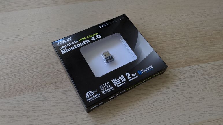
Searching on that error message, I found more information in this GitHub issue filed against Noble, which pointed to a Noble document explaining that support is limited to a fixed list of hardware. Not surprisingly, the chip on board my experimental laptop was not on the list. I searched for the hardware on that list, and thought the Asus USB-BT400 (*) was cheap enough to order and give it a try.
For the BT400 to function under Noble, I also needed to circumvent the normal driver installation process and instead install WinUSB so Noble can directly access the hardware to bypass Windows’ Bluetooth stack. The WinUSB installation link in Noble Wiki is dead, but a web search pointed to this link as the modern replacement.
Once WinUSB driver was installed for the Asus USB-BT400 Bluetooth adapter, Noble was able to find it and didn’t crash when I attempted to discover nearby BLE devices. Unfortunately, neither did it find any of the BLE hardware I had on hand for this test. I had hoped that, even if I couldn’t use that hardware, I could at least discover their presence.
This test was not a success, ah well. Life moves on to other experiments.
(*) Disclosure: As an Amazon Associate I earn from qualifying purchases.