Quick Look: Jakob Krantz Mars Rover

Since the time I’ve published my Sawppy rover project, I’ve learned of a few other rover projects with no relation to Sawppy (other than being inspired by the same rovers on Mars) but also utilize 3D printing. These are far more affordable than trying to duplicate the mechanical workings of a rover in LEGO. This collection also happens to hail from around the world. The first stop of this world tour is Sweden, home of a rover published by Jakob Krantz titled simply “Mars Rover”. It uses commodity PVC pipes for suspension structural members instead of the aluminum extrusion beams I used on Sawppy. The overall size is slightly larger than Sawppy, with different proportions. For example, the wheels and body appear to be smaller than proportional to Curiosity. But it is recognizably and undeniably inspired by NASA JPL Mars Rovers.

Full rocker-bogie is presented and accounted for, including 3D-printed links for the differential. Sawppy didn’t use 3D printing for these parts, it used the same hardware used on the JPL Open Source Rover. They are adjustable suspension link turnbuckles from the remote control car world, and I have yet to think up or find a 3D printed design that worked as well as those turnbuckles. It’s not clear how Krantz’s design handles rotation across multiple degrees of freedom and browsing the published CAD file only shows gaps where some critical components of the joint (bearings? bushings?) would sit. How these differential links function remains a mystery to me for now.

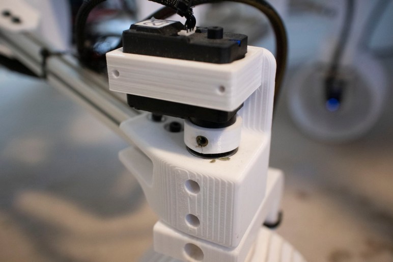
The published parts list included several bearings, all of which appeared to be used in the rocker-bogie suspension. Examining its CAD file confirmed that all wheel forces are sitting directly against the drive motor gearbox, and all corner wheel forces are directed into the steering servos. I prefer to have ball bearings handling such forces instead of the motor gearboxes directly, and designed Sawppy to use a pair of 608 ball bearings at each rotational joint. Perhaps overkill, but it’s what I like to have.

On the electronics side, Krantz’s rover uses ESP32 for its brains. As a powerful and affordable microcontroller with wireless capability, it is a very good choice for robotics projects. Especially since it is now one of the supported Micro-ROS architectures for interfacing with ROS2. I haven’t seen any interest from Krantz about putting ROS2 on his rover, but the option is there if he wants to.

And there’s plenty of time for future work. Like Sawppy, this rover is a long-term project of Jakob Krantz who has been working on his rover for at least a year. Or at least, there were two Hackaday writeups for his project a year apart. It is a labor of love and I know that well. It’s a journey that Frédéric Jelmoni has recently embarked on for a younger rover project focused on Perseverance.

Window Shopping LEGO Rovers

After seeing circuit boards being used as structural members in the 4tronix M.A.R.S. rover, I realized that I had forgotten a very fertile field: LEGO! My interest in mechanical systems today is something I give full credit to the LEGO sets I had growing up. My LEGO creations grew more complex as I grew older, limited only by my toy budget. However, once I got up and running on 3D printing objects of my imaginations, I haven’t touched my big box of LEGO since. I quite enjoy the freedom of not being constrained by what LEGO pieces are available.

Among currently available LEGO sets, there is a tiny little Mars rover as part of the LEGO CITY Mars Research Shuttle (60226). The set is quite affordable, but about the only thing its little rover has resembling Curiosity rover are the number of wheels. Beyond that, there is no rocker-bogie and no corner steering, which is not a surprise at this price point.

Moving up the price and complexity scale is the LEGO NASA Mars Science Laboratory Curiosity Rover (21104), released in 2014 and no longer in production. This was part of the LEGO Ideas program where people can submit their LEGO designs and, if enough other LEGO fans voted in favor, the LEGO group will consider adapting it for production. This particular idea received over 10,000 supporting votes and became an official product. Perusing its assembly instruction PDF, I was surprised to find that this rover has a fully articulating rocker-bogie suspension. Very impressive! I also sadly learned that it required several pieces that I lack in my own LEGO collection, so I couldn’t “just” follow the directions to build one of my own. At some point I could go hunt for the few missing pieces which should be cheaper than buying this out-of-production kit on eBay. People are asking over $100 for a used kit and as much as $1,100 for a never-opened box. That’s more than two Sawppy rovers!

But if price is no object, I can look to other LEGO creations people have posted. There are quite a few “LEGO rover” projects online, and it follows roughly the same trajectory as the past few window shopping posts: most don’t even have six wheels, some have six wheel rocker-bogie but no corner steering, etc.

An example of a rover with corner steering is this LEGO MINDSTORM NXT creation. Despite being constrained by the selection of available LEGO pieces, it nevertheless replicated some features that I skipped with my 3D-printed rover. One example being the spokes in each of the six wheels, which I had simplified for 3D printing but the builder here faithfully represented more of the curves. And they have a robot arm, which my Sawppy is still waiting for. But according to the text, only the four corner wheels drive leaving the middle wheels free-wheeling. And it’s not obvious if the rocker-bogie articulates faithfully. At the very minimum, this design is missing the differential bar across the top.

This rover looks to be roughly the same size as my Sawppy rover, but the price tag would be significantly higher. There are six visible NXT brains on this invention: five on board the rover and one for the handheld remote. Each $350 MINDSTORM NXT box comes with a single NXT brain, so this rover costs at a minimum 6 * $350 = $2,100 dollars. Yikes.

So as far as LEGO rovers go, the best ones that implement features I consider important are build-it-yourself designs by enthusiasts and not available as commercial products. Thus we return to the world of 3D printing, where Sawppy isn’t the only rover design floating around.

Window Shopping 4tronix M.A.R.S. Rover

Wheeled robot kits calling themselves rovers are plentiful, but rarely do they faithfully represent the JPL rovers sent to Mars. ServoCity’s Bogie Runt Rover at least is a six-wheel chassis with rocker-bogie suspension, but is missing the corner wheel steering system. Looking for commercially available products out there with six wheel drive rocker-bogie and four corner steering, I was almost ready to conclude none existed until I came across the 4tronix M.A.R.S Rover Robot.

The name is an acronym for Mobile Autonomous Robotic System and the autonomy comes from the brainpower of either a Raspberry Pi Zero or BBC micro:bit. Out of all the commercial products I’ve come across, M.A.R.S. has the most mechanically faithful model of Curiosity and Perseverance suspension geometry. It has roughly similar proportions, and uses a differential arm over the body. Sojourner, Spirit, and Opportunity use a differential inside the body in order to maximize top surface area for solar panels. The nuclear-powered Curiosity and Perseverance didn’t have such constraint. By moving the differential above, they gained body interior volume.

Perusing the assembly instructions I see the structural components are all printed circuit boards (PCB) which is not usually considered structural material but apparently can be made to work at this scale. Six wheel drive comes from N20 micro gear motors, and four wheel steering comes from MG90S metal gear micro servos. Both of these are fairly widely available for maker projects and good choices.

My quibble with the M.A.R.S. rover are with its rotational motion joints. First up are the rocker-bogie suspension components, each of the joints are a M3 screw inside a PCB hole. I’m queasy about using fasteners as axles, since their threads are not really designed to carry a load. There are no bearings on these joints and the screws have to be tightened precisely. Too tight, and the joints would bind. Too loose, and the rover will wobble. This seems awfully finicky and would loosen as the rover travels.

Second, each wheel’s weight is transferred directly into the N20 micro gearbox. Examining pictures of these gearboxes online, it does not appear the gearbox is designed to handle loads perpendicular to rotational axis. Perhaps the rover is lightweight enough the load would be fine, but all I see are metal shafts turning inside holes in brass plate.

And third, each of the corner steering wheel assemblies are attached directly to the steering micro servo’s horn. Despite the metal gears, MG90S type servos still has a great deal of flexibility and play in its gearbox in the face of loads perpendicular to rotational axis. We can see each corner steering assembly wobbling noticeably while in motion:

(I also smiled when I realized this video cuts out right when the rover starts tackling a very challenging vertical climb. We’ll never know if it managed the climb.)

The final quibble I have with this design is that the steering axis is not aligned with the wheel. In less formal terms, it means the wheel is sideways offset from its corresponding steering servo instead of sitting directly under the servo. As a result, when the steering servo rotates, its wheel isn’t pivoting about a point. Instead, it is dragged through an arc. This adds a great deal of mechanical stress to the steering mechanism. It also makes the desired wheel velocity harder to calculate through a turn, but it appears the M.A.R.S. software skips that detail. All left side wheels are commanded to turn at the same rate, and all right side wheels are the same with each other. As a result we can see a bit of wheel skid through a turn, reintroducing some of the problems of using a strictly skid steer system as the Bogie Runt Rover did.

In conclusion M.A.R.S. has the mechanical sophistication of corner steering in addition to a good representation of rocker-bogie suspension, but its current iteration does not yet take full advantage. Still, it looks like a nifty little kit and the price of one hundred pounds is significantly lower than the cost of parts for Sawppy.

This concludes my quick tour of commercially available rover kits. But before I move on to DIY rovers, there’s a rover category that bridges across both “commercial product” and “do it yourself”: LEGO rovers.

Window Shopping ServoCity Bogie Runt Rover

The littleBits Space Rover is a cute little thing, but with only two wheels it bears little resemblance to real life Martian robot explorers. Moving a little bit higher on the fidelity scale, there are some robots out there with six wheels arranged in a rocker-bogie geometry. A representative of this breed is the ServoCity Bogie Runt rover.

Browsing the ServoCity web site, it appears that the Bogie Runt is the largest and most complex (so far?) of their line of “Runt Rover” chassis kits. Peewee, Sprout, and Zip Runt Rovers are two-wheel differential drive chassis like the littleBits Space Rover. Then there are the Junior, Half-Pint, and Whippersnapper Runt Rovers which roll on four wheels. The Bogie Runt is the only one with six wheels, and the only one with an articulating suspension system.

On ServoCity’s “Robot Chassis Kits” page they are all listed under “Smooth Surface.” This is certainly true for all the other Runt Rovers, but the Bogie Runt should be able to handle rougher terrain thanks to the rocker-bogie suspension system. It’s not obvious if the smooth surface classification for Bogie Runt was a mistake, or if it was deliberate based on information not immediately visible from just window shopping.

All of the Runt Rover kits appear to be made by laser (or possibly waterjet) cutting of flat materials, likely some type of plastic. They have bolt patterns to connect with ServoCity’s Actobotics build system which is mostly aluminum. Actobotics is very popular with FIRST Robotics participants and because of that, it was also the build system selected for the JPL Open Source Rover.

But that also causes a problem I have with the Bogie Runt: Actobotics is based on Inch dimensions and thus problematic for use outside of the United States. Sawppy is metric and, for worldwide compatibility, I plan to keep all derivatives and descendants metric.

Another shortfall of Bogie Runt is the lack of corner steering mechanisms. It is thus constrained to differential drive (a.k.a. “Tank Steer”) which works very well for two wheels but precision drops as the number of contact patches go up. In my experience, differential drive is marginal for four wheels, and behaves unpredictably with six. It was a tradeoff the Bogie Runt Rover product made against cost and complexity, leaving room for improvement and motivation for me to keep looking.

Window Shopping littleBits Space Rover Inventor Kit

Before I start getting too ambitious with making my personal rover project more like a user-friendly commercial product, I should look around to see if a product already existed. There are a lot of robot kits out there trying to earn that STEM education money, and some of them do try to get a slice of the excitement around our interplanetary robotic explorers. And while some of them are interesting and have their own merits, most of them lack features that I consider critical in a rover relative.

A representative example is the Space Rover Inventor Kit from littleBits. I like the idea of littleBits, giving beginners a very friendly way to explore electronics by making components with magnetic connectors. This makes electrical connections easy and also helps avoid beginner mistakes like accidentally reversing electrical polarity. The downside is that the customer has to pay a premium for this capability, and it’s not a premium that I’ve been personally willing to pay. This particular kit has a MSRP of $200 USD, and for that kind of money I would much rather build my own robot. (Though at time of this posting, the kit is on sale for $30.)

As a supplement to generic electronics beginner kits, littleBits also apply their technology to some themed offerings like this Space Rover kit. All the electrical components are reusable and remixable littleBits centered around a robot control module. The module is interesting because it interacts with a phone app, giving the rover remote control capabilities. But I also see the app as a disadvantage: as I understand it, the app would discourage experimentation. If the user changes the rover around, it wouldn’t take much before it exceeds what the phone app can gracefully handle. Thus motivating the user to leave it in the space rover configuration, defeating the point of using littleBits to begin with.

But in my eyes the biggest shortfall of this rover is its two-wheeled differential drive chassis. Similar to what home robot vacuums like Roomba uses. This is fine for flat indoor ground, which is what earthbound rovers mostly end up doing anyway. So as a home education toy this is a good technical choice. But for fans of rocker-bogie like myself, this is sorely lacking and we must look elsewhere.

But at least this little Space Rover has an arm. Looks like it only has one degree of freedom, which is very limiting, but that’s one more degree of freedom than Sawppy’s nonexistent robot arm. Victory: littleBits Space Rover!

Sawppy Cost and Complexity

Sawppy is just like every other project in that there’s a long list of ideas of things to do. I’ve been blabbing here for a while about problems and ideas to fix them, most recently about how hard it is to carry Sawppy around. But all those ideas have to balance the benefit against cost. Not just in terms of money, but also in terms of construction complexity.

I designed and built Sawppy as a lower-cost alternative to the JPL Open Source Rover, giving up on capabilities in exchange for a lower monetary barrier to entry. Using serial bus servos allowed a much simpler electrical system, though they contributed problems of their own. Mechanically, the construction complexity of both rovers are not very far apart in no small part to the large number of fasteners in both designs.

This was because my primary audience for Sawppy was myself, and I aimed at my own strengths and avoided my weaknesses like wiring. This was fine for the rover builders out there who have similar or superior skills, but it left out people who want a rover but didn’t have the same background. I know of rover builders who were stuck on the software, or on the electrical, or 3D-printed all the parts but never found the time to go through the time-consuming process of putting everything together.

Some people who didn’t have the same skills and background as I did found my Sawppy documentation lacking. Most were apologetic as they asked for help, others were… less polite. One notable person was unhappy that I didn’t provide detailed electrical wiring schematics and blasted the project for it. Dude… I give Sawppy out for free, if you’re unhappy I’ll refund your $0. Piss off.

Rude self-entitled people aside, there is clearly an unmet need. Sawppy was designed for people who are likely to tinker and modify my design, so many things were left loose and open to interpretation and customization. The freedom of choice can be disorienting for some, so there are people who would appreciate a rover that is not only cheaper and simpler to build, but also a corresponding set of prescriptive step-by-step directions to get there.

This starts to sound like what people expect in a commercial product. And there are a few already out there. So what ground have already been covered, and what can I do that’ll be different? It’s time to window shop a few products, starting with the littleBits Space Rover.

[Headline image: Sawppy at MatterHackers Modern Creators event. Behind Sawppy is Tamara @tlynnr85 promoting her Seekers of Science project.]

Sawppy Issue: Portability

Sawppy’s top speed is approximately 40 times faster than the scaled top speed of Curiosity rover. Even then, it is the pace of a very slow walk and I frequently pick up my rover to walk faster. Which leads to the next problem: there’s no good way to carry Sawppy. The cool rocker-bogie suspension gets in the way of using any piece of aluminum extrusion beam as a carry handle, and even when I try to do so, Sawppy looks really undignified when carried that way. It looks better for me to slide my arms under the main body and lift. Sawppy remains upright, but my arms get tired very quickly. And the dangling rocker-bogie still keep bumping into things.

Sawppy is also pretty awkward when I need to carry further than walking distance. I built Sawppy to be roughly the same size as the JPL Open Source Rover, but more precisely I built Sawppy to be roughly the largest size that I can still carry in my car. I’m not ready to buy a larger vehicle for the sake of carrying a rover.

For walkable distances, SGVHAK rover is ferried about by a collapsible wagon. I thought that would be a good idea for Sawppy but have yet to get one of my own. And that still doesn’t solve the problem of taking up a lot of space in a car.

The real Mars rovers have a provision to fold up compactly for their journey to Mars. The tall camera mast folds down, and so does the rocker-bogie suspension. Sawppy has not duplicated either of these capabilities, and I think it might be time for Sawppy to learn to be a little more flexible for long trips. Thanks to some helpful friend-of-friends networking, I found out that the suspension folding mechanism is the “Rocker Deploy Pivot”. (Thank you, @LongHairNasaGuy) Knowing the official terminology is the key to start researching for more details. Studying the real thing aids contemplation for adapting a simplified form for Sawppy.

For walking distance trips, several options are possible. I could get a wagon like the one for SGVHAK rover, or I could build some kind of a skateboard for Sawppy to ride. I should also think about adding a carrying handle to Sawppy somewhere. So many things I can add to Sawppy, but doing too much risks making an overly complicated rover.

Sawppy Is Both Too Fast And Not Fast Enough

Sawppy was designed to be a motorized scale model of Mars rover Curiosity and Perseverance that faithfully replicates their rocker-bogie suspension geometry and articulation, which is really cool for rough terrain but overly complicated for flat ground. Sawppy also have wheels heavily inspired by Perseverance, which is designed for Mars but rather less great here on planet Earth.

Rolling around on those wheels is a signification deviation from source material. Sawppy crawls around fairly slowly, just under 40 centimeters per second. This is roughly the speed of a toddler learning to walk. But even that is far faster than scale speed. Curiosity has a maximum speed of four centimeters per second (0.144 km/hr or 0.089 MPH.) Sawppy is roughly quarter scale, so matching scale means rolling with a maximum speed of one centimeter per second, just barely faster than a snail. On Mars there’s not much of an incentive to hurry and the robot explorers can take their time. Here on Earth we have no patience for that kind of speed and hyperactive kids would quickly lose interest.

The target speed is also reflected in the suspension geometry. A Mars rover would never go fast enough to catch some air, and thus would not need the ability to absorb impact of landing. My Sawppy going 40 cm/s is not a lot of stress, but anyone hoping to build Sawppy into a high speed dune buggy will be sorely disappointed. Bob Krause of Inventor Studios coaches a FIRST Robotics team, and they investigated adapting Sawppy to be their competition robot. Given the drastically different design constraints between Mars exploration and FIRST Robotics, they concluded this suspension design is the wrong choice for a competition where speed is essential, and I agree.

Because for all practical purposes, Sawppy’s “40X scale speed” is still too darned slow. The speed is fine when I’m doing something like casually cruising a Maker Faire looking at all the exhibit booths. But if I am on a schedule and have somewhere to be, I end up picking up Sawppy to carry by hand.

Sawppy Wheel Traction Has Downsides And Upsides

Sawppy copied the rocker-bogie suspension system from Mars rovers Curiosity and Perseverance, who are destined to roam Martian terrain. But Sawppy on Earth mostly roamed flat ground instead of uneven terrain. This made the suspension largely superfluous except for contrived demonstrations, adding complexity and weight that is not strictly necessary. But I love it anyway, as a tribute to our Martian robotic explorers.

Another tradeoff Sawppy inherited from the big rovers are the wheels. Sawppy’s wheels surfaces are designed to mimic that of Perseverance rover. Grousers (raised ribs on the surface) designed to scrabble over sand and rock struggle to find grip on asphalt or concrete. This is not a problem for Curiosity and Perseverance as there is no asphalt or concrete (or carpet, or tile…) on Mars. But Sawppy struggles on made-for-human interiors.

Most wheeled vehicles on Earth use rubber tires of some type for traction. Many different varieties are available, optimized for different surfaces. Mars rovers do not use rubber tires because rubber (both natural and synthetic) would quickly break down in the Martian atmosphere. They are also quite heavy, and weight is a constant enemy for anything launched into space. Which is why Martian rover wheels are lightweight thin-shelled metal constructs designed just tough enough to handle all known Martian terrain. Unfortunately, Curiosity’s wheels have been torn up by some unknown Martian terrain. Lessons learned from engineering tests led to redesigned wheels on Perseverance that should better handle its voyage.

But none of that are of concern for Sawppy rovers here on Earth, so various rover builders have explored improving wheel traction. Chris Bond replaced the wheels with RC monster truck wheels, similar to those on JPL Open Source Rover. Steve’s Tenacity rover got some rubbery overshoe to fit over standard Sawppy wheels.

But increasing traction could also magnify other problems making them worse. With my wheels, a Sawppy rover can be tolerant of minor steering angle misalignment, the wheel will just slip sideways a bit as it rolls. With high-traction wheels, steering angle misalignment would start pulling the wheel towards/push it away from the body, twisting the suspension geometry. This has proven to be a problem with JPL Open Source Rovers and their high traction rubber tires. This is not very noticeable when driving short distances, but minor steering alignment eventually become a big problem for longer drives.

Sawppy Issue: Terrain Mismatch

Backing off from specific design issues like steering trim adjustment, I want to note a general problem with public demonstrations. Sawppy is an approximately 1/4 scale model of Mars rovers Curiosity and Perseverance, faithfully replicating the geometry and articulation of their rocker-bogie suspension systems designed for traversing Martian terrain. Down here on planet Earth, Sawppy has historically not spent much time rolling on Mars-analogue terrain. Most of the time, when I take Sawppy out for show-and-tell, my rover is rolling on surfaces like asphalt, concrete, carpet, hardwood, or tile.

Mars doesn’t have any of those surfaces. With such luxuriously flat and smooth environments, there’s not much opportunity for Sawppy to show off how nifty a rocker-bogie suspension is. I found myself manufacturing challenges out of what’s on hand, which is why instead of sandy dunes or rocky fields, Sawppy finds itself running over feet…

… and backpacks.

Fundamentally, Sawppy is out of its element on smooth terrain. Robots optimized for flat ground would not need the capabilities of a rocker-bogie suspension system, where it is far more complex and heavy than required for the circumstances. But every once in a while, a Sawppy rover gets to visit a someplace resembling its natural habitat, such as when Aussie Sawppy took a trip to the beach.

This is the kind of terrain the rocker-bogie suspension — and the wheels — are designed for.

Sawppy Issue: Steering Angle Adjustment

I haven’t heard much feedback on the next topic, this is mostly my experience with my own Sawppy. The root cause here are the output shaft angle sensors used in inexpensive servo motors such as the LewanSoul/HiWonder LX-16A serial bus servos used on my rover. For the most part, they are just inexpensive potentiometers, and they are not terribly consistent. In practice, this means steering angles on each of Sawppy’s four corner steering servos are a little different for every Sawppy driving session. I don’t know all the variables involved, there’s probably some combination of temperature, humidity, or maybe even the phase of the moon. Who knows?

One solution is to buy better components with precision angle sensors. But since an overriding goal of the project is to keep the rover affordable and accessible, I’m going to resist going down that path as much as I can.

Sawppy was designed with a way to adjust steering center angle. What I had in mind were the set screws and where they dug into the steering shaft, which would have been a relatively unmoving thing. So Sawppy steering trim is adjusted by the rover chassis configuration file that is loaded by the software at bootup. This would have been fine if it was something a rover builder only had to do once when building the rover. I did not anticipate steering would fall out of trim on a recurring basis, and requiring this file be edited for every driving session is a huge hassle.

SGVHAK rover also had a trim adjustment issue. That rover’s steering motors had relative encoders but had no homing reference point so it didn’t know where “straight ahead” was upon bootup. Since I expected it to have to be adjusted on every startup, I added a menu in software to perform steering trim adjustment. This is friendlier than a configuration text file, but it was a multi-step process that takes at least thirty seconds per corner. I still consider that too much work.

For a future rover revision, I intend to add some mechanical mean to compensate for drifting potentiometers. I want to loosen something (using screwdriver, or wrench, or even a tool-less contraption if I’m clever) to release the corner steering mechanism, steer the wheel by hand to desired alignment, and tighten things back down. Ideally I want to adjust the steering angle in under 10 seconds per corner.

The JPL Open Source Rover uses high quality (and expensive!) steering angle sensors. The sensor angles have no such drift to speak of, but the steering shafts do sometimes slip inside their steering couplers resulting again in misaligned wheels. Fortunately, these sensors are easily accessible and with a crescent wrench I could turn the sensor inside their mounted position to adjust trim. This is the kind of adjustment I want.

I have a very crude equivalent for Sawppy right now. Sometimes I have an emergency and need to adjust steering trim in a hurry. I can loosen the set screw in the steering servo coupler, steer the wheel manually, and tighten that set screw back down. This only worked because the set screws I bought from McMaster-Carr are much harder than steering shaft material, so tightening it would dig a new hole at the desired position. But I could only do this a limited number of times before the shaft is too chewed up to hold any angle and I need to cut a new shaft.

But it taught me that a mechanical steering trim adjustment mechanism is fast and easy to use. I just need to find a way to preserve that user experience in a more well-thought and more enduring design. Even if Sawppy’s suspension system is rather underutilized most of the time.