My Saleae Logic 8 analyzer is now tapped into communication between the mainboard and face plate of a tape deck. A quick examination of the captured data looks reasonable, now it is time to dig into the data, compare against the LC75853 datasheet, and understand what is going on with LCD output control.

Within the ~3/4 second of the faceplate getting power, this sequence is transmitted repeatedly approximately once every 5 milliseconds. Zooming in, I see they are three consecutive CCB transmissions to address 0x42:
| Address | 1 | 2 | 3 | 4 | 5 | 6 | 7 |
|---|---|---|---|---|---|---|---|
| 0x42 | 0x00 | 0x00 | 0x00 | 0x00 | 0x00 | 0xC0 | 0x10 |
| 0x42 | 0x00 | 0x00 | 0x00 | 0x00 | 0x00 | 0x00 | 0x80 |
| 0x42 | 0x00 | 0x00 | 0x00 | 0x00 | 0x00 | 0x00 | 0x40 |
Guided by the datasheet, I interpret them as:
- Most of the 0x00 bits indicate the corresponding LCD segment is to be turned off.
- Some of the 0x00 bits in the second and third set are fixed data.
- In the first set, the two bits in 0xC0 maps to S0 and S1, which controls sleep mode. S0 =1 and S1=1 is one of three available sleep modes.
- Also in the first set, the single bit in 0x10 translates to SC, the segment on/off control data. SC=1 means display state is off.
- For the second and third set, they each have a single bit that appear to be fixed within the section labeled as DD (direction data) and their values written into the timing diagram.
After that initial ~3/4 of a second, the pattern makes a minor change and repeats less frequently: once every 50 milliseconds:
| Address | 1 | 2 | 3 | 4 | 5 | 6 | 7 |
|---|---|---|---|---|---|---|---|
| 0x42 | 0x00 | 0x00 | 0x00 | 0x00 | 0x00 | 0x00 | 0x10 |
| 0x42 | 0x00 | 0x00 | 0x00 | 0x00 | 0x00 | 0x00 | 0x80 |
| 0x42 | 0x00 | 0x00 | 0x00 | 0x00 | 0x00 | 0x00 | 0x40 |
The two bits associated with sleep mode are now zeroes. Sleep flags S0=0 and S1=0 means “Normal operation”, so the chip is awake. SC is still 1, though, so LCD is still off.

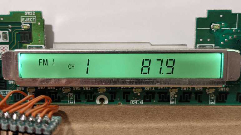
Then I pressed the power button. This triggered a set of events (probably related to key scan reporting) that I will investigate later. Right now, I am focused on how the LCD control message changed to display “FM 1 CH 1 87.9”
| Address | 1 | 2 | 3 | 4 | 5 | 6 | 7 |
|---|---|---|---|---|---|---|---|
| 0x42 | 0x00 | 0x00 | 0x00 | 0xD0 | 0xDD | 0x02 | 0x00 |
| 0x42 | 0x70 | 0x55 | 0x00 | 0x00 | 0x00 | 0x00 | 0x80 |
| 0x42 | 0x06 | 0x04 | 0x0B | 0x00 | 0x00 | 0x00 | 0x40 |
The end of first set changed from 0x10 to 0x00. This cleared the SC flag, so now LCD is on. There are other control bits in the first set of bytes and they are all zero.
- K0 and K1 set to zero means none of the key scan pins were reassigned to segment control duty, so the chip retains ability to scan up to 30 keys.
- P0 and P1 set to zero means none of the segment pins were reassigned to digital output duty, so the chip can control a maximum of 120 segments.
- DR set to zero means 1/3 bias drive voltage.
The display backlight is also illuminated now, but which of these bits are responsible? For now, that is still an unknown. Until I get more information otherwise, I’ll proceed on the assumption that all remaining bits are LCD segment control.

To get more information, I pressed the “Mode” knob changing the display to “BAS 0” and its control message to this:
| Address | 1 | 2 | 3 | 4 | 5 | 6 | 7 |
|---|---|---|---|---|---|---|---|
| 0x42 | 0x00 | 0x00 | 0x00 | 0x00 | 0xC0 | 0x02 | 0x00 |
| 0x42 | 0x0D | 0x80 | 0xDC | 0xF4 | 0x2F | 0x02 | 0x80 |
| 0x42 | 0x00 | 0x00 | 0x00 | 0x00 | 0x00 | 0x00 | 0x40 |
That’s a lot of changes!

For a smaller delta, I turned the knob one step so it now shows “BAS 1”.
| Address | 1 | 2 | 3 | 4 | 5 | 6 | 7 |
|---|---|---|---|---|---|---|---|
| 0x42 | 0x00 | 0x00 | 0x00 | 0x00 | 0x80 | 0x02 | 0x00 |
| 0x42 | 0x00 | 0x80 | 0xDC | 0xF4 | 0x2F | 0x02 | 0x80 |
| 0x42 | 0x00 | 0x00 | 0x00 | 0x00 | 0x00 | 0x00 | 0x40 |
This is a more manageable set of changes. A single step changes “0” to “1”, which on a 7-segment display means turning off four segments. A change from 0xC0 to 0x80 turns off one bit, and from 0x0D to 0x00 turns off three bits. This matches expectation of deactivating four segments.
I didn’t take pictures for the next experiment: While in FM radio mode, I press the tuner up button once. This moved it off the first preset so “CH 1” disappeared and now the display shows “FM 1 88.1”:
| Address | 1 | 2 | 3 | 4 | 5 | 6 | 7 |
|---|---|---|---|---|---|---|---|
| 0x42 | 0x00 | 0x00 | 0x00 | 0x10 | 0xD1 | 0x02 | 0x00 |
| 0x42 | 0x7F | 0x55 | 0x00 | 0x00 | 0x00 | 0x00 | 0x80 |
| 0x42 | 0x00 | 0x00 | 0x0B | 0x00 | 0x00 | 0x00 | 0x40 |
Then I pressed it again, so it now displays “FM 1 88.3”:
| Address | 1 | 2 | 3 | 4 | 5 | 6 | 7 |
|---|---|---|---|---|---|---|---|
| 0x42 | 0x00 | 0x00 | 0x00 | 0xD0 | 0xD9 | 0x02 | 0x00 |
| 0x42 | 0x7F | 0x55 | 0x00 | 0x00 | 0x00 | 0x00 | 0x80 |
| 0x42 | 0x00 | 0x00 | 0x0B | 0x00 | 0x00 | 0x00 | 0x40 |
All changes are in the first part of the control message. Changing from 0x10 to 0xD0 turns on two bits, 0xD1 to 0xD9 turns on one bit. These added up to the three activated segments, matching expectation of going from a “1” to “3” on a seven-segment numeric display.
These observations give me confidence that we are indeed looking at control bits corresponding to individual segments on screen. Not enough information to map out all the segments to their corresponding bits, but I am postponing that task until I have individual control through code. It would be much easier to map out segments when they are under my control. And if I fail to obtain control, I wouldn’t care about the segment map anyway.
With some confidence I understand the output side, now to look at the input side.
