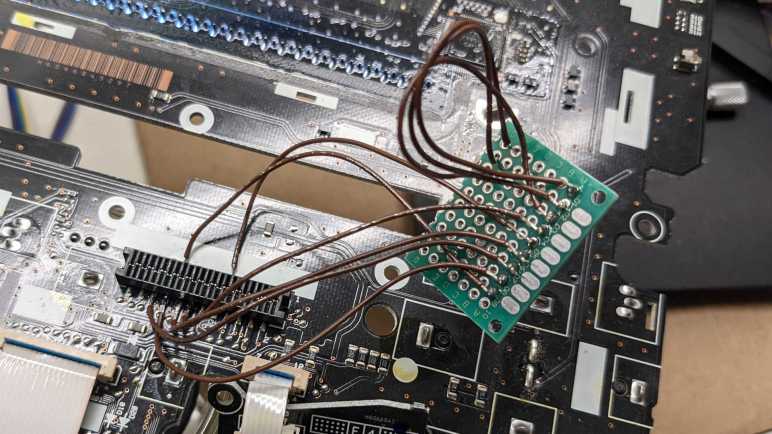
I have a Honda in-dash CD (and HVAC) control board and I want to see if I can make its LCD work. After I melted through conformal coating over the Sanyo LC75883 LCD driver chip, I was able to get an electrical connection with my meter so I can test for continuity between the pins (that are too fine for me to solder) to something I can more easily work with. I quickly found that much of the CD player functionality is connected to a small black rectangular connector I noticed earlier. Not just the LCD driver chip’s data communication lines, but also the big central rotary knob and button.
There is a large degree of uncertainty here, because I didn’t find what all of the pins did. I also found two pins that both appear to be ground, and I don’t know if there’s an important distinction between those two pins. This incomplete understanding explains the problems I will encounter later.

Using the numbers on the circuit board silkscreen, the pins are 1 to 24 from right to left. (Silkscreen shows 1 in the upper right, 2 in the lower right, 23 in the upper left, and 24 in the lower left.)
| Pin | Preliminary Name | Description |
|---|---|---|
| 7 | Vss (?) | Either 7 or 9 is ground, maybe both? |
| 9 | Vss (?) | Either 7 or 9 is ground, maybe both? |
| 14 | Vdd | +5V power supply |
| 16 | DO | CCB Data Out |
| 17 | DI | CCB Data In |
| 18 | CL | CCB Data Clock |
| 20 | CE | CCB Chip Enable |
| 21 | A | Encoder A, connects to ground when knob is at certain positions. |
| 22 | B | Encoder B, connects to ground when knob is at certain positions. |
| 24 | Button | Connects to ground when “AUDIO PWR” button is pressed |
Once these connections were made, I could make further progress. That is, running into an entirely different set of headaches.
