SevenStock 20

Today was SevenStock 20 and I attended with my RX-8 in her BB-8 Halloween costume. Last year I attended SevenStock with the costume only partially completed. This year it is complete but a little faded from running around over the past year under SoCal sunshine. It was still plenty distinctive in the row of RX-8 lined up in the show & display area. Many people took pictures, some even took me up on my hint and posted on Instagram tagged with #rxbb8.

Out of all the cars on display, the one that stood out to me was ironically not a rotary-powered vehicle at all. It was a Mazda R360, Mazda’s first car built in 1960. By modern standards an adorable tiny little thing. It was on display at the Mazda corporate area along with other Mazda vehicle currently on the market. Which meant the little 1960 Mazda was utterly dwarfed by the modern Mazda SUVs on display.

Mazda R360 Next To Current Mazda SUVs

There were many powerful speed machines on display, but I kept coming back to admire the little R360 that can barely reach highway speed. There are four seats in the car but I don’t see how four adults can fit in this little box. It looked closer in size to a kid’s Power Wheels car!


SevenStock takes place on the infield of the Auto Club Speedway and the track itself was open during the event for people who paid a fee and can pass safety inspection. There was a sizable contingent who love the idea of driving out on the oval but for one reason or another passed on the high-speed track time.

This year the organizers tried an experiment: a “parade lap” to get a taste of driving on a banked oval via a bit of token track time. The thundering herd was led by the trio of historical rotary-power race cars brought by Mazda, and we stopped a few times on track for the scattered pack to organize. Here’s a picture taken during one of the on-track stops.

Rotaries On Track

The price of admission for the “parade lap” was $15, and I thought it was well worth it for the novelty value of taking my car on a real high-speed track. Even if we were only going at city-street speeds.

Reading the PIC32MX1XX Datasheet As A PIC16F18345 User

A review of the Hackaday Superconference 2017 “camera badge” hardware provided adequate orientation but no lightning strike of project inspiration. Today I did find the project page for last year’s Supercon badge as well as a summary page of some things people have created with the 2016 badge. People have done some really cool things with that badge serving as foundation. I’m feeling intimidated but also determined to keep trying to see what I can devise.

Today’s tactic: Dive into the data sheet for the Microchip control unit at the heart of the 2017 badge, the PIC32MX170F256D. No matter what else happens, it would be good to have an overview of what the chip can and can’t do. I was also hoping that a review of the data sheet will unveil something about the chip that would inspire a project. Since I’ve already read the PIC16F18345 data sheet back-to-back, I hoped the familiarity with Microchip conventions will give me a head start.

The first surprise was the size (length) of the data sheet. Only 344 pages when the much simpler PIC16F18345 chip had a 491 page document. It didn’t take long for me to figure out why, since every feature section started the same way: a disclaimer that the data sheet was only the summary and tells me I need to do more reading if I want the details.

OnlyASummary

Well, that explains the size! For my purposes today, it’s no big deal. In fact it is helpful since the summaries mean I don’t have to press “Page Down” as often.

There are some comfortable commonality with the PIC16F18345 I’m familiar with: Timers and comparators. Digital I/O and analog input (ADC.) Communication via SPI, I2C, UART. And all these peripheral modules are mapped into a memory space so everything is accessed via memory reads and writes. And finally: a big focus on power management.

There are some differences that I might miss in the PIC32MX1XX:

  • PWM seems to have gone missing, unless there is a much more advanced component that can serve similar purposes but I don’t recognize it as such.
  • I/O pins are much less powerful. The PIC16F can handle up to 50mA on any single I/O pin and up to 250mA total. The PIC32MX can only handle 15mA per pin with 200mA total.
  • Narrower voltage range: Unlike the super flexible and relaxed PIC16F that is happy to run with anything from 2.3V to 5.5V, the PIC32MX prefers to stay within 2.3V to 3.6V. The maximum is listed as 4.0V, so it might be dicey to run this thing on a single rechargeable lithium cell – the nominal voltage is 3.7V but a fully charged cell might be up to 4.2V.

The PIC32MX uses a different instruction set (MIPS32 M4K) and that’s no surprise. I expect to be mostly isolated from this fact by writing in C and letting the XC compiler worry about the instruction set. The PIC32MX also requires more support circuitry. Whereas the PIC16F can literally connect directly to a battery and it’ll start running. Again I’m mostly isolated in this case because the camera badge is already built for me and all the support components are already on board.

And now, on to the things that might be interesting. I started with the title description: “32-bit Microcontrollers (up to 256 KB Flash and 64 KB SRAM) with Audio and Graphics Interfaces, USB, and Advanced Analog

The first thing to catch my eye: USB, backed by this promising-sounding bullet point on the cover page: “USB 2.0-compliant Full-speed OTG controller“. USB OTG would let us plug-in USB peripherals and greatly expand the possibilities of what we can do. Alas, my hopes were dashed when page 2 clarified that USB OTG is only on the PIC32MX2XX series and absent on the PIC32MX1XX we have on the camera badge. So that’s out.

The “Advanced Analog Features” bullet items seem to mostly center around support for capacitive touch sensing, mostly around their “mTouch” design. Since their reference implementation involves copper traces and plates on a printed circuit board, that won’t be directly applicable to me. But perhaps this type of support circuitry can be hacked into something fun.

I have yet to explore the world of audio electronics, so sadly the audio interface features are mostly gibberish to me. I had higher hopes for the “Graphics Interfaces” side of that claim and… I came up empty-handed. There’s nothing that obviously said “graphics” to me on the feature set. The closest thing I can find is the PMP (Parallel Master Port) peripheral which is good for talking to display panels, and is indeed already employed on the camera badge to drive the 128×128 OLED screen.

So in the category of “stuff that the chip can do, but isn’t already being used” the best candidate at the moment is the analog circuitry to support capacitive touch. Since I don’t have time for a OSH Park PCB, it’ll have to be something creative. Perhaps something as primitive as taping down loops of wire to cardboard or 3D-printed plastic parts.

The gears in the brain keep churning…


Supercon 2017 Badge – Hardware Orientation

Today was spent getting orientated on the hardware components making up the camera badge for Supercon 2017. The starting point is the project documentation’s “hardware description” page, which gave a basic overview that helps me decide where I want to dig deeper.

2413581507673490011

The CMOS sensor at the heart of the OV9650 camera module claims to support up to 1280×1024 resolution, which isn’t bad for such an inexpensive component. The sample image posted on the project file section, however, is only 128×96 resolution. It’s not immediately clear where >99% of the pixels disappeared to or how feasible it’d be to bring them back.

Perhaps that resolution was chosen to match the OLED screen, which has 128×128 pixels of resolution controlled by a SSD1351 chip. If this is the case, and more pixels can be captured from the camera with minimal effort, that opens up project ideas such as having the little screen pan across a larger image. (a.k.a. the Ken Burns effect.)

We have multiple tiers of storage that makes different capacity/speed trade-offs. First we have some space for data on the PIC itself, then we have a Microchip 23LC1024 serial RAM, and finally a microSD card.

There’s an LIS2HH12 accelerometer on board which might enable some cool projects, though I’m struggling to think up one that captures my fancy. Maybe in a bit.

The chip that orchestrates all of this is a PIC32MX170F256D. Fortunately for me, I already had the tools on hand to develop for it thanks to my time playing with the PIC16F18345. They’re very different chips, but since they’re both from Microchip I would write code to both using the same MPLAB X IDE albeit with different C compiler underneath: XC8 vs XC32. The PIC32 is set up to run a .hex file off the microSD card, so it’s not necessary to have a PIC programmer. But if I need to flash at a more direct level, the board has headers to connect the same PICkit 3 programmer I use for the PIC16F18345.

All in all, a decent set of hardware. Now I just need to think of a really cool project to do with it all.

Supercon Badge – Initial Exploration

Supercon 2017 is coming up soon and I now have a ticket to attend. Part of the fun is the badge which, unlike SIGGRAPH or WestTec, is not a printed piece of paper. In the case of Supercon (and a few similar conferences) it is actually a circuit board with some functionality. The Supercon 2017 badge is a very minimal low resolution digital camera. Why would we want such a thing when most of us carry cell phones with far superior cameras? Because it is only the start: conference attendees are invited (expected?) to use it as a starting point and build something cool.

Which means I have only about 10 days to do my homework – what would I build with the badge? As a first-time attendee I’m not sure what to expect. Last year I saw brief glimpses of the badge under construction, but I didn’t see any of the projects built by conference attendees.

Well, with any project, the first step is to look for documentation. The official source of information is, naturally, the camera badge’s own project page on Hackaday.io. I felt intimidated on first look: my own adventures in electronics hardware hasn’t covered anything to do with cameras, OLED panels, or the like. About the only thing I am vaguely familiar with is the microcontroller at the heart of the device. It is a Microchip PIC, though from their PIC32 series which is higher-end and more capable than the PIC16F chips I had been playing with.

Fortunately, it uses the same MPLAB X IDE for development. I had to download and install the XC32 compiler corresponding to the PIC32 chip, but that was relatively easy. After changing the path separators from the author’s Windows machine (‘\’) to the Ubuntu I’m working on (‘/’) the project builds successfully.

That’s a good start. The next step is to go digging through the code base and look for something interesting for me to do.

cambadgebuild


What Happens When You Don’t Drain Water From Your Compressed Air Tank

Alternate title: I looked inside a corroded air tank and now I kind of wish I hadn’t.

During the disassembly of our thermoforming machine, we noted with worry that the compressor doesn’t have an air dryer between it and the tank, and that the tank is installed in such a way that the water drain valve is basically inaccessible. So any water in the compressed-air system (and due to basic physics, there definitely will be some) would have accumulated in the tank over its years of service.

A short while ago we got far enough in the rebuild to test the compressed air subsystem. Not surprisingly, the compressed air tank leaked and could not hold pressure. Upon closer inspection the leak appears to be rust perforation implying the inside is pretty rusty. So we replaced the tank instead of trying to patch it.

10 - Rusted hole

But I was curious: OK, it’s rusty. But how rusty? During a lull in projects (waiting for some parts to arrive) I pulled out the angle grinder, attached the cutting wheel, and merrily started making sparks.

20 - Grinder

As I made progress cutting, I noticed chunks of degraded metal were falling out of the gap I had cut. Not flakes of rust – chunks of varying color and texture. This is my first hint things are about to get ugly. Once I cut enough to pull away the end of the tank, we can see inside.

30 - Cut open

That’s far more corrosion than I had expected. And while most of the inside surface qualifies as “rusty” the bottom part deserves a stronger word. I can think of a few, but the only one I am willing to put in print is “Yuck”.

40 - Closeup

This sight is something I might expect to see in a home plumbing project fixing the sewer pipe. And this stuff has the soft squishy consistency of… well, the kind buildup you’d find in a sewer drain. This is not something I expected to see inside a piece of industrial equipment.

50 - Full Length

This layer has built up across the entire bottom part of the air tank.

I had originally thought it’d be neat to find the other side of the perforated hole but I was not in the mood to dig through this muck. Even while wearing gloves.

So let this be a lesson to everybody: If you have a compressed air tank, be sure to drain the water out of it regularly, or this might happen to you!

(Cross-posted to Hackaday.io)

Building a Tiny “Joule Thief”

Yesterday I got a “Joule Thief” (a.k.a. Armstrong self-oscillating voltage booster) circuit up and running on a breadboard. The circuit was more complex than it needed to be, with a tangle of wires, because things got messy while debugging. But now that I know which parts connect to which, it’s time to simplify.

The goal is to make it small and compact enough to package together as a single-battery LED flashlight. That general goal broke down to the following parts:

  1. Minimize physical size. Since the coil is the largest single piece (other than the AA battery) it makes sense to align the diameter of the coil to the battery and pack everything else as tightly inside as I can.
  2. Minimize component count. Most Joule Thief examples on the internet (including the top picture on the Wikipedia page) soldered the legs of the individual components together. No circuit board needed.
  3. Friendly to hand soldering. There are some ready-made Joule Thief circuits for sale on the internet using surface mount components and a circuit board. I wanted something I can build by hand and maybe use as a soldering teaching project to be shared on the internet.

After a few iterations, I have something I’m happy to share with the world. This is purely about the mechanical assembly – the electronic schematic is identical to the one in the Wikipedia article linked at the top of this post.

An overview in words:

  • The resistor for the NPN transistor base is installed between the collector and emitter. The resistor acts as physical separation in order to avoid a short-circuit.
  • The transistor and LED are pointing in opposite directions, allowing their pins to point towards each other and soldered together. The aforementioned resistor keeps the LED anode and cathode separate.
  • The transistor is stuffed into the middle of the coil, utilizing the center volume.

The build sequence in pictures:

1 - Transistor
Transistor with the base bent in preparation for resistor installation.
2 - Transistor Resistor.jpg
The 1K Ohm resistor is installed on the base, between collector and emitter.
3 - Transistor Resistor Coil
The coil has two wires wound together. One end of this dual-coil is facing the camera, the other end facing away. Since we need to wire up the coil in opposite directions, we’ll bend one wire of the front pair towards the back, and the opposite back side wire to the front.
4 - Coil prep.jpg
The two wires now facing away from the camera are soldered together to become the positive terminal of the circuit. One of the two wires facing the front will be soldered to the resistor, and the other to the emitter.
5 - Transistor in Coil
Transistor in the center of the coil. Now the coil wires can be soldered.
5a - Resister soldered
Resistor soldered to one coil wire, all the others have been trimmed short in preparation for attaching the LED.
6 - LED
LED is soldered to the circuit, as is a wire to act as negative (return) wire.
7 - AA
Install the whole assembly in front of a 3D-printed AA battery tray: Let there be light!

Building a “Joule Thief”: Adventure in Analog Electronics

One of my early memories as a little kid playing with my battery-powered toys was the realization that battery exhaustion is not an absolute thing. A set of AA batteries that could no longer run a motorized toy aren’t completely useless – they could be installed in an electronic toy and make that light and beep. I turned it into a little game for myself: swapping batteries around trying to figure out which tired worn batteries would work in which toys.

A well-meaning adult saw this activity and thought they saw a poor child frustrated by dying batteries. He or she (I have no memory of the person, only their action) tried to help by taking away the worn batteries and giving me a fresh pack of AAs. They were understandably confused when their well-intended kindness were rewarded by an upset toddler in tears.

Many years later I would learn how electric motors demand more current than microprocessors along with their effect on battery power output, thus explaining my childhood observation. I understand what’s going on now, but I still try to pull every bit of power out of a non-rechargeable battery before they are disposed.

Which is why my eyes lit up when I learned of a circuit that can power a LED from a “dead” battery. Wikipedia says the official description is “Armstrong self-oscillating voltage booster” but it’s filed under “Joule Thief“, the pun name that I usually see.

This type of electronics projects venture beyond the digital world I’m familiar with. There’s no voltage representing 1 and 0, instead it works with voltage that oscillates. Specifically, I’ve never worked with the fields generated by wires coiled around a toroid core. The first few attempts – using either hand wound coils or savaged from electronics – failed. And I didn’t understand enough to diagnose if it’s the coil or the circuit.

This time around, I took a shortcut: I bought a pack of coils (*) with customer comments that confirm they can be used for building Joule Thieves. This way, if the circuit didn’t work, I knew it was my fault and not the coil. And indeed, the first few attempts failed because the coil was not correctly connected to the rest of the circuit. (The key phrase I missed in the Wikipedia article: “the two windings are connected in opposing directions”.)

Attached is the picture of the first iteration that actually worked, powered by a “dead” AA battery. This circuit is unnecessarily complex because I had been moving parts and wires, around trying to understand where I made my mistake. But now that I have a working Joule Thief I can start simplifying and make a more compact version.


(*) Disclosure: As an Amazon Associate I earn from qualifying purchases.


Thermoforming Machine Low Amperage Systems Test

We got far enough wiring (and re-wiring) the thermoforming machine to perform an integration test of the low-amperage parts of the machine. This covers almost everything except the heating element.

LowAmpTestSuccess

On the previous test of the compressed air subsystem, we found a leak in the air tank. The leaky tank has since been replaced and this will be a test to see if it works with everything else.

The vacuum subsystem had also been partially tested earlier. For the previous test we only got as far as the vacuum table solenoid. This time we also have the vacuum lines between the solenoid and the vacuum table.

The relay panel had been tested with the following configuration:

  • 24V bench power supply as the input.
  • Manually connecting the control wires in turn like an old style telephone switchboard.
  • Multi-meter reading the output.

This time, the test will put the relay panel in a more realistic configuration:

  • Power will come from the 240V AC to 24V DC power supply on the DIN rail.
  • The control signals will come from the manual operation toggle switch panel.
  • And the most exciting part: the outputs are going to the actual air and vacuum components!

There was much anticipation and trepidation when the power switch was thrown the first time and we see LED indicators on the power supply indicating the system was live. Every switch thrown was a “Will it work?” mystery. The test did its job, exposing a few wiring errors. Fortunately none of them were damaging mistakes and all were trivial to fix.

At the end of the evening, we could control everything except the heating element using the manual operation switch panel: Move all the air cylinders, open and close all the air valves, and activate the electromagnets that hold the frame closed.

We still have lots of things on the to-do list, including some air leaks to track down and fix and plenty of wiring tasks. And there’s still the big intimidating heating element looming in the near future. But all in all, a wonderful morale boosting step on the journey to completion.

(Cross-posted to Hackaday.io)

Relay Replaced Instead of Bypassed on Monoprice Maker Ultimate (Wanhao Duplicator 6)

After the due diligence investigation of my broken Monoprice Maker Ultimate (a rebadged Wanhao Duplicator 6) I determined my unit has indeed suffered the known common failure of the main 24V relay. I was also satisfied as to the cause of the failure – it was the consequence of engineering design decision I disagreed with, driving a relay far above its rated rating of 10 amps. But I was unsatisfied with the internet forum wisdom of bypassing the relay when it fails. I thought it had a useful purpose to serve and should be replaced instead of bypassed.

I ordered a replacement (or more accurately a pack of them (*), since it makes little sense to buy or sell a single unit of something so cheap) and got to work once they showed up. The first order of business was to get out the label machine and label all the wires connected to the control board so I know where everything plugged back in. The wires were held in place with dabs of hot glue to resist them from being shaken loose in transit, those globs had to be removed before I could disconnect the wires. After that’s done, the board came out easily.

Before I started de-soldering anything, I performed a quick verification test on the new relay: I connected 5V across the control pins and heard a reassuring “click”. Multi-meter confirmed that the continuity shifted from the NC (Normally Closed) to NO (Normally Open) pin as expected.

After that, it’s time to heat up the soldering iron. Normally I would label the old component “BAD” before starting on the project, to make sure I don’t de-solder a broken component and inadvertently soldered the bad item right back onto the board. (This is the voice of experience speaking.) But in this case, the melted hole is a pretty good way for me to tell which is the bad one.

It takes some effort to de-solder a component with 5 large pins like this relay, but nothing tricky. It just requires a lot of patience with the de-soldering tools at hand. And once done, the new relay soldered into place easily.

With this replacement, my 3D printer is back in action with all original functionality intact.


(*) Disclosure: As an Amazon Associate I earn from qualifying purchases.

The Ever-Growing Wiring Job

When we started on this thermoforming machine rebuild project, one of the first things we did was to open the control panel. We looked at the nest of wires back there and tossed the whole tangled mess. Those control wires were a basket case we’re happy to leave behind. But the rest of the machine – the power cables and such – looked OK at first glance.

Unfortunately, they don’t look as good after the second or third glances. Sometimes it’s not a glance at all – it’s seeing (and feeling) them fall apart when we worked in the machine. We expected the wires to be old, and kept our eyes open for signs of aging wires. We just didn’t expect to see them quite so often! This particular example was from the back of the air compressor. When we wanted to clean up the air compressor, we had to disconnect these wires. The act of moving the wires for access and removal broke the age-hardened insulation in many places. So now we have to replace it.

Failing insulation

Every time we get to work on a new area, we find that a new bunch of wires need to be replaced. We’re rapidly approaching the point where it might be easier to rip out every single wire and restart from scratch.

Wiring is tedious work, part of why good electricians make good money. For us, it’s a very real threat against project completion. We’re interested in having our own thermoforming machine, but that interest tends to drop every time we discover 2 new wiring tasks for every one completed. It’s a race to complete before everyone loses interest in the project.

Hopefully the work will be much easier – or at least more rewarding – once the wiring is complete.

Assuming, or course, we get there…

(Cross-posted to Hackaday.io)

Vacuum Table Frame Removal

Around the periphery of the vacuum table on the thermoforming machine, the previous owners built a perimeter using L-brackets. The presence of the frame made sense to help seal in the vacuum. The mystery is the height: The vacuum table and its surrounding frame are the same height as the combined height of the top and bottom parts of the frame holding the workpiece. We had expected the vacuum table to be aligned with the bottom part of the frame, since that’s the height the workpiece will be held at. As this frame is double the height, it would have impacted the workpiece on the way down. We’re left scratching our heads figuring out why this is desirable.

But that mystery isn’t important right now. Since we intend to put this machine to work on low-volume hobbyist projects, we will want to change the size of the workpiece frequently. This would be difficult with the existing system, since changing the size of the workpiece means changing the surrounding frame, greatly increasing the up-front setup work. It might be fine for a commercial production machine but such a barrier on a hobbyist machine would probably mean we’d be too lazy to actually use it.

We’re bouncing around a few ideas that should make it easier to change the size of the work piece in the machine. All of those ideas are incompatible with this existing taller-than-expected frame, so it needs to be removed.

A few jabs with a metal putty knife got things going and the frame popped off shortly afterwards.

Frame Removal

Then the tedious part starts: the putty knives went to work scraping off the sealant that was liberally applied to the bottom of the frame.

Putty Removal

Part of the motivation to invent a new vacuum sealing system is visible here: this surface is quite scratched up and rusty. To make it seal properly with the old system, we need to remove all the paint, sand things flat, and put on a new smooth coat of paint. If we can avoid that work with a clever new sealing system, we’d be happy.

(Cross-posted to Hackaday.io)

Investigating the Infamous Relay Bypass for Monoprice Maker Ultimate (Wanhao Duplicator 6)

This week my 3D printer stopped working mid-print. All motor movement, heating activity, and cooling fans stopped simultaneously. However, the control panel is still responsive and so is the LED light strip. Time to hit the web and see what I can find.

My printer is a Monoprice Maker Ultimate, which is a rebranded Wanhao Duplicator 6. Which is in turn a knock-off of the Ultimaker design, though not a literal clone of any specific Ultimaker model.

A web search of my symptoms found a known point of failure with this product: the main 24V relay. The popular explanation is that Wanhao cloned somebody else’s circuit board, removed the features that would use the relay, and used a cheap relay that’s always on. So the recommended workaround is to solder a wire to bridge the legs of the relay and bypass it. “It doesn’t do anything anyway.”

I was skeptical of this explanation because if Wanhao is really just cutting costs, they would skip the relay entirely: no relay is cheaper than any relay! There must be more to this story.

But first, a check to see if the relay is indeed the fault. A quick visual inspection confirmed that there’s a problem with my relay, indicated by the melted hole in the side. For additional confirmation, we temporarily bridged the pins as recommended by forum posters. When done with the power on, it brought the always-on heat break and circuit board cooling fans immediately to life. Relay failure confirmed.


What does the relay do?

Turning off this relay cuts power to all 24V components: Motors, fans, and heaters. In normal operation, there’s no situation where the 5V components (micro-controller, display, LED strip) are running without the 24V components, so the answer must be related to abnormal operation. Our best hypothesis: this relay is a safety switch in place to halt the system if the 5V subsystem should fail. If that happens, it makes sense we’d want to shut down all the 24V parts too. And now that we have a plausible description of the relay as a safety feature, bypassing it with a soldered wire seems like a bad idea.

Why did the relay fail?

This part was easier to figure out. When I ran my printer with my Kill-A-Watt meter, it indicated the power draw jumps by over 300 watts when both heaters are active. So even ignoring the cooling fans and motors, the print bed and filament heaters together draw over 12.5 amps from the 24V plane.

Typing in the designation on the relay “SRD-05VDC-SL-C” found its datasheet, which says the relay can handle 10 amps. So the printer was designed such that the relay exceeded its rated capacity anytime both heaters are active. Not exactly a great design. The relay tolerated this overworked condition for many months but this week it could take no more.

The correct solution, then, would be to replace this relay with a higher-rated unit that can handle 15+ amps continuously. (12.5 for heaters + motors and fans + margin.) Unfortunately relays are not standardized in their footprint so I failed to find a drop-in higher-capacity replacement. (I found the Omron G5LE series with the same footprint, but with the same 10A maximum for DC so I’d be no better off.) Hooking up a beefier relay to the circuit board via wires is a possibility but intimidating. 300 watts of electricity is very good at finding minor flaws and turning them into big problems.

What do we do?

To summarize, the candidate solutions are:

  1. Bypass the relay with a wire as per internet forums: Seems like a bad idea to bypass a potential safety feature.
  2. Install an exact replacement: Known to work until it doesn’t.
  3. Install a higher-rated drop-in replacement: Great idea but such a replacement could not be found.
  4. Install a higher-rated unit elsewhere in the box, connect to the circuit board via wires: Adds many points of potential failure and >300W of power is unforgiving of flaws.

I’d love #3 but I couldn’t find a beefier relay with identical footprint. #1 and #4 are asking for trouble. For the immediate future, I choose #2 as the least-bad solution.


UPDATE 1: After the original relay was replaced with an identical unit, I cut open the original relay to see inside the failure.

UPDATE 2: As expected, the identical unit eventually failed in an identical way.

Ball Aerospace COSMOS: Open Source Command and Control

COSMOSToday’s entry for “neat stuff I stumbled across on the web” discovery is COSMOS by Ball Aerospace, an open-source command-and-control system for embedded systems. It has been added to my candidate list of software platforms to drive low-level hardware projects.

My primary target for high-level infrastructure has and still remains ROS, but COSMOS will have its place in projects yet to come. The strengths of COSMOS is that it is already designed for specific scenarios around telemetry gathering and display so should be better suited for projects in that category. ROS also has telemetry capabilities but it is less focused on displaying that data to the user.

A robot running ROS is concerned about the data, but it is more concerned about what it should do in response to that data. COSMOS has less focus there. A command-and-control system gathers the data, shows it to the operator, and the operator decides what to do. COSMOS can send commands to the systems it is monitoring but the thinking between the input (data) and output (action) is mostly left open for the human operator and/or task-specific custom software. It feels like a platform for building my own SCADA system. It will also be useful for times when the project is purely a data-gathering operation with no response necessary.

COSMOS is written in Ruby using the Qt framework. I have a working knowledge of Ruby thanks to my exploration with Ruby on Rails, and I also have a minimal working knowledge of Qt thanks to the Tux Lab thermoformer project with the Raspberry Pi GUI. That experience should make things easier if I ever decide to get serious using COSMOS for a future project.

HaasTec = Machinists’ Amusement Park

A few weeks ago I walked through the exhibition floor of WESTEC and had a great time looking over all the displays. There were Haas machines on the show floor, but they’re CNC grinders from a German company. Not the Haas based in Oxnard, CA. I’m told the two companies were founded by different men with the same family name but not related.

Haas Automation – the home team based in Oxnard, CA – did not participate in the industry trade show. They opted to hold their own event instead. Called HaasTec, I went and as an aspiring machinist I had a great time.

Haas subcontracts out the metal casting operations around the world. Those castings are brought to Oxyard to be machined and assembled. The Haas manufacturing floor is an endless parade of highly automated machinery working on their assigned jobs with minimal human supervision. Many of which are Haas machines built in the very same factory.

Haas Factory 1

There were more people present on the assembly side of the factory floor, with machines in various stages of assembly. The manufacturing workflow is tracked in a computer database and we happened to catch a production manager with some time and he was enthusiastic enough about the system to walk us through a few of his everyday tasks that he can perform on his iPad. It was fascinating to see how high-tech the whole process has become.

After the factory tour we walked through the showroom and watched various sales representatives put machines large and small through their paces cutting metal. As a fun side bonus, we can take home some of these demo pieces as souvenirs.

It was well worth the >3 hours (round trip) drive to attend the event. I certainly enjoyed it much more than I would anything they could have set up on the WESTEC exhibition floor.


Haas Automation is Surprisingly DIY-Friendly.

HaasLogoI hadn’t paid much attention to Haas Automation until recently. When I took my machining classes, there were no Haas machines in the school shop. My awareness of the company did not extend very far beyond the fact a Haas machine is on the cover of my textbook.

That changed recently because Tux-Lab is a fan of Haas Automation. The machine tools (which I aspire to operate) are all Haas machines. I started learning about them and the more I learned, the more I liked what I saw.

First, they are the Home Team. Based in Oxnard, CA, roughly two hours drive away from where I currently live. It is challenging to operate a manufacturing business in the USA, never mind Southern California, and I’m happy to see they’ve found some measure of success in the face of overseas competition.

Second, they have transparent pricing of their equipment listed on a web configuration tool. No “contact your sales representative for a quote” runaround. I’m sure large customers can (and do) negotiate a discount, but at least there’s a price up there on the screen to let people know what they should expect.

The third and most important thing that impressed me: they are friendly to customers who wish to work on their own machines. Sure, they have the standard disclaimer “[work] should be done by authorized trained personnel” but they publish a lot of useful reference information for those who wish to forge ahead anyway. Most other machine tool companies do not publish this information. These non-DIY-friendly companies tell their customers to “contact your authorized service representative.”

And lastly – Haas open their doors to customers (and potential customers) during HaasTec, their own open-house event. See the factory in action, see Haas machines building more Haas machines. That sounds like a Disneyland trip for machining geeks, sign me up!

Motivation to Review My Machining Textbook

Many years ago I developed an interest in machining so I could tackle projects that demand capability beyond pliers and a Dremel tool. I found evening classes offered by Lake Washington Institute of Technology (formerly Lake Washington Technical College). The campus is only a short drive from where I lived at the time. I enrolled in the Machining Technology program on the theory I could learn by attending classes on my way home after work.

In reality I only managed two quarters of classes before my full-time job demands picked up so much I could no longer keep up the night classes. Since I’m unlikely to stock my own home workshop with industrial-level machine tools, I wrote the whole thing off as a self-enrichment learning exercise with no practical application. Or I almost did, because I kept my textbooks on the chance I would need them again.

That was a good thing, because another opportunity has now presented itself. There are a few machine tools at Tux Lab which gives me motivation. If I can get myself up to speed again and prove I’m not likely to break the machines, I might be able to return to those ideas that needed more than a Dremel tool. (And in the years since, I would add “… or a 3D printer.”)

So I dusted off my many-years-old textbook and started reviewing the fundamentals because I believed the fundamentals of machining has not changed. Computer software has evolved tremendously in this time but metal is metal. Still, I was curious about the current status of the book so I looked it up on Amazon.com. My textbook is Machining and CNC Technology (First Edition) by Michael Fitzpatrick (*). As an old textbook, it is going for far less than what I had paid.

According to Amazon, a second edition and third edition has come and gone and we’re now on the fourth edition (*). And because it is the latest and specified by college instructors, the price is over $200. Ouch!

Even in the age of Amazon, the college textbook market is still very distorted.


(*) Disclosure: As an Amazon Associate I earn from qualifying purchases.

A 3D-Printed Enclosure to Take My LED Project On The Go

For the Connect Week event put on by Innovate Pasadena, the Hackaday LA group is hosting the “Bring-A-Hack” event where attendees are encouraged to bring projects (in any stage of completion) for show and discussion. Since I’ve been building my LTC-4627JR driver board as a learning project, I wanted to bring it in for show-and-tell.

Now I could just bring the assembled circuit board and pass it around as an inert object, but what fun would that be? I wanted to bring in something that shows it doing something, and provide some way for people to interact with the whole contraption. Looking at my parts on hand, it seemed easiest to rebuild my thermometer test project. I can have a simple Python program run on the Raspberry Pi, reading temperature from the Tux-Lab Si7021 breakout board, and sending it out to my display. That makes 3 circuit boards, plus they’ll need portable power. I will enlist my Amazon purchases: the 3-cell lithium ion battery pack protected by a S-8254A IC, and the MP1584 buck converter to translate the battery pack’s power into Raspberry Pi friendly voltage.

They present a logistics challenge. There are many parts and while it’s fine to just connect them with wires on my work table, it’s too unwieldy to carry on the Gold Line to Pasadena. I’m going to need some kind of enclosure to carry the whole thing.

To Fusion 360 we go! I just needed a simple enclosure so it was pretty fast to draw up. The bottom tray is for power: it holds the battery cells, their protection board, and the buck converter to 5 volt output. The upper tray holds the Raspberry Pi. The lid of the tray holds my custom LED circuit board, and a few clamps holds it all together. The clamps should be easily removable so I could disassemble the box to show people what’s inside.

ShowandTellBox

I had originally intended to mount the Si7021 breakout board as well, but ended up deciding it would be more fun to have it dangling out for people to play with it. Here are the layers without the clamps, so they can be taken apart and show off the insides.

IMG_5273

And here’s the “travel configuration”, with clamps holding the pieces together.

IMG_5274

This setup worked well. I was able to carry it in my backpack without worrying about tangling up or shorting out wires. Once I arrived, the project was fairly well received and lots of people had fun playing with the thermometer.

PIC Controller for LTC-4627JR LED Now Accepts Strings

Now that our circuit board from OSH Park is populated and running, it’s time to evolve the PIC code beyond displaying a test pattern. The objective of the exercise all along was to display data sent to the unit over I²C, but the exact details of what to send hasn’t been finalized.

Stage 1: Raw Bits

This was the easiest and so was the first thing we implemented. It is the lowest-level way to communicate between the host and the display. The host sends data in the form of raw bytes. Each bit in a byte correspond to the 8 segments in a single digit. The host sending 4 bytes will fill 4 digits. We send that byte directly out to PORT C on the PIC micro controller, which are connected to 8 segments of a LED digit.

This method is powerful in the sense it allows the host to display arbitrary patterns. But it is terribly unfriendly to use. The program running on the host has to tailored to the implementation details of our display: the host has to know which bit corresponds to which segment, and whether a bit value of 0 or 1 corresponds to light or dark. Which means if the user wants to swap out to a different display, they would have to rewrite the host code.

This system served its purpose to prove we could light the LED, but it is not a good way forward.

Stage 2: Hexadecimal Decode

In this system, the bytes sent by the host is decoded into their hexadecimal representation and displayed on screen. Since a hexadecimal digit represents 4 bits, the host sending 2 bytes (16 bits) will fill the 4 digits. This is actually a pretty useful mode in certain debugging operations where we do want to see those values. However, it is very difficult to represent human-friendly information this way. We’re also unable to make full use of the LTC-4627JR this way: there’s no way to represent the decimal point or the colon in the middle.

Since it is useful for machine-level (not human-readable) data debugging, we might want to retain this capability in the form of a special mode later. In the meantime, let’s move on.

Stage 3: Binary-Coded (Hexa)Decimal

The next evolution resembled binary-coded decimal system, which separated out each digit to its own byte. This makes the host program easier to write because each character can be treated individually instead of having to pack 2 characters into the upper/lower 4-bits of a byte. Unfortunately it also shares the limitation that we couldn’t represent the decimal point or the colon.


Which brings us to the latest approach:

Stage 4: String

Since most computer operations that result in human-readable information end up with the string data format, we’re going to try using that as our I²C protocol. It is established, well-understood, and a piece of cake to use from high-level programming languages like Python. The downside is that it is much more verbose. The character sequence to light up all the LED is 8.8.:8.'8. which requires 10 bytes to represent. This is a five-fold increase in bandwidth relative to the 2 byte hexadecimal decode. Will this added bandwidth cause problems? I don’t know yet, we’ll find out.

But for now, we have a very user-friendly interface. Sending the string “79.2F” resulted in the picture attached to this post. The easy interface also enabled a very short example program.

(The project discussed in this blog post is publicly available on Github)

IMG_5272


Qt Quick with PyQt5 on Raspberry Pi

QtLogoThe prime motivation for me to go through Qt licensing documentation and installing Qt Creator IDE was to explore the new UI infrastructure introduced in Qt 5 under the umbrella of “Qt Quick“. As far as I can tell, this is an entirely different system for creating user interface of a Qt application. Built with modern ideas such as OpenGL graphics acceleration for animation effects and UI layout declared with a text-based markup language QML (probably stands for Qt Markup Language.)

Up to this point my experience with building graphics user interface in Qt was with the QWidget-based infrastructure, which has a long lineage in past editions of Qt. Qt Quick is new for Qt5 and seem to share nothing in common with QWidget other than both a part of Qt5. Now that I’ve had a bit of QWidget UI work under my belt I wanted to see what Qt Quick has to offer. And this starts with a smoke test to make sure I could run Qt Quick in the environments I care about: Python and Raspberry Pi.

Step 1: Qt Creator IDE Default Boilerplate.

Once the Qt Creator IDE was up and running, I followed the Qt Quick tutorial to create a bare bones boilerplate Qt Quick application. Even without any changes to the startup boilerplate, it reported error messages complaining of missing modules. Reading the error message, I looked at the output of apt list qml-module-qtquick* and installed the ones that sound right. (From memory:qml-module-qtquick2qml-module-qtquick-controls2, qml-module-qtquick-templates2, and qml-module-qtquick-layouts)

QML CPP

Once the boilerplate successfully launched, I switched languages…

Step 2: PyQt5

The next goal is to get it up and running on Python via PyQt5. The PyQt5 documentation claimed support for QML but the example on the introductory page doesn’t quite line up with the Qt Creator boilerplate code. Looking at the Qt Creator boilerplate main.cpp for reference, I translated the application launch code into main.py. This required sudo apt install python3-pyqt5.qtquick in addition to the python3-pyqt5 I already had. (If there are additional dependencies I forgot about, look for them in the output of apt list python3-pyqt5*)

QML PyQt

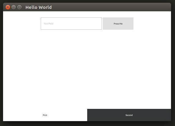
Once that was done, the application launched successfully on my Ubuntu desktop machine, albeit with visual appearance very different from the C++ version. That’s good enough for now, so I pushed these changes up to Github and switched platforms…

Step 3: Raspberry Pi (Ubuntu mate)

I pulled the project git repository to my Raspberry Pi running Ubuntu Mate and tried to run the project. After installing the required packages, I got stuck. My QML’s import QtQuick 2.7 failed with error module "QtQuick" version 2.7 is not installed The obvious implication is that the version of QtQuick in qml-module-qtquick2 was too old, but I couldn’t figure out how to verify version number is indeed the problem or if it’s a configuration issue elsewhere in the system.

Searching on the web, I found somebody on stackoverflow.com stuck in the same place. As of this writing, no solution had been posted. I wish I was good enough to figure out what’s going on and contribute intelligently to the discussion!

I don’t have a full grasp of what goes on in the world of repositories ran by various Debian-based distributions, but I could see URLs flying by on-screen and I remembered that Ubuntu Mate pulled from different repositories than Raspbian. I switched to Raspbian to give that a shot…

Step 4: Raspberry Pi (Raspbian Stretch)

After repeating the process on the latest Raspbian, the Qt Quick QML test application launches. Hooray! Whether it was some configuration issue or out of date binaries we don’t know yet for sure, but it does run.

That’s the good news. Now the bad news: it launches with the error:

JIT is disabled for QML. Property bindings and animations will be very slow. Visit https://wiki.qt.io/V4 to learn about possible solutions for your platform.

And indeed, the transition between “First” and “Second” tabs were slow. Looking on the page that it pointed to, it looks like the V4 JavaScript engine used by Qt for QML applications does not have JIT compilation for Raspberry Pi’s ARM chip. That’s a shame.

For now, this excludes Qt Quick as a candidate for writing modern responsive user interfaces for Raspberry Pi applications. If I want to stick with Qt and Python, I’m better off writing Qt interfaces in the old school QWidget style. We’ll keep an eye on this – maybe they’ll add JIT support for Raspberry Pi in the future.


(The source code related to this blog post are publicly available on Github.)

Qt Licensing Means Reading Big Walls of Text

QtLogoFrom a legal perspective, Qt is an interesting beast. There are two sets of licenses for application developers who wish to use Qt: a commercial license, or an open-source license. I’m sure this “dual-license” approach is intended to let people have the best of both worlds. In practice, it means people who try to do their legal due diligence will have to wade through a lot of legal language. It’s a very challenging barrier – most of the Qt Frequently Asked Questions page is devoted to licensing.

And that’s the condensed version. The legal Terms and Conditions section has multiple pages dedicated to different aspects of using Qt. As a non-lawyer, it’s very hard to not let my eyes gloss over the thick language. Even if we just focus on just the open-source side of the licensing, there is an array of licenses to worry about. There are the strong GPL , the more permissive BSD licenses, and the LGPL that attempts to strike a balance between them. I didn’t even know about LGPL until today. All of them are in play for various parts of Qt.

Fortunately, since my work so far is not for profit, and I intend to put everything up in public on Github, most of the terms of the open-source license should be easy to meet. I would definitely need to consult a lawyer before embarking on a commercial project, though.

With this basic due diligence complete, I went looking for the open-source edition of the Qt tools. They don’t exactly make it easy to find on the official Qt downloads page. It takes some persistence to navigate through the menu structures, looking for the de-emphasized texts and links, to find the download areas for the free open-source edition.

Before I found that compiled binaries repository, I found the information to build Qt5 and Qt Creator from source code. It seemed to be confused by the Qt (both 4 and 5) that appeared to already exist on my Ubuntu installation and I never got the home-built Qt5 up and running. After I stumbled across the binaries repository, I decided to come back to building Qt5 from source after I’ve gained a bit more experience with Linux build systems.