Windows Phone 8 As Sawppy Rover Controller

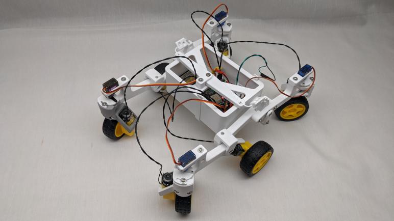
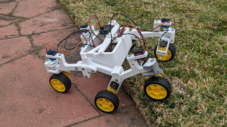
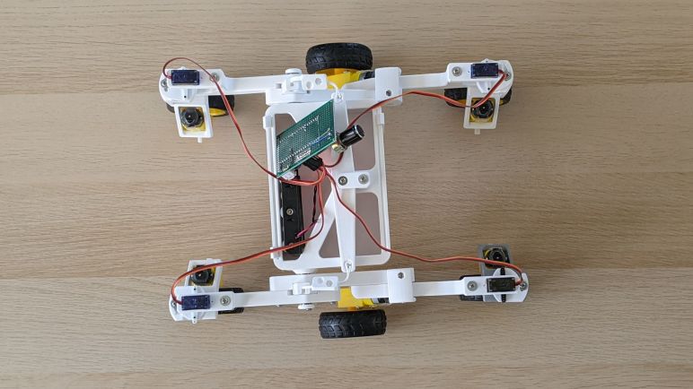
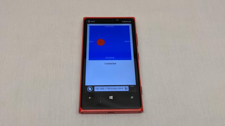
I wanted to reduce the cost of a micro Sawppy rover by using a HTML-based WiFi control system. This allows control by any web-enabled device like touchscreen phones that many people already carry. However, since it would be against the cost-reduction theme to require expensive new flagship devices, I’m aiming at the opposite end of the spectrum: if people don’t want to use their everyday phone, they should be able to use their old retired phone for rover driving duty. As a representative example for development, I will be using my old Nokia Lumia 920 running Windows Phone 8 (updated to WP8.1.)

Microsoft stopped supporting these phones in 2017, which includes shutting down their app store. (Which never grew to the scale of iPhone or Android app stores.) Any new functionality would thus have to come in via its mobile-optimized version of Internet Explorer. Which, by accounts of the day, made a respectable implementation of web standards of the era. Unfortunately, mobile sites of the time were too frequently written explicitly for Safari on iPhone or Chrome for Android. Mobile-friendly web standards existed at the time and was supported by all the platforms, but not yet as widely adopted by sites as they are today. This was a problem that also hampered Firefox’s attempt at a phone OS.

Since this is not an iOS device, nor an Android device, I expect any web-based code that runs on IE for WP8 would be neutral and will run across many older devices. Or if they do not, at least I hope starting from this neutral ground means any necessary modifications would be minimal.

I actually had the intention of making my original SGVHAK rover code friendly to old phones as well, which was part of why I adopted jQuery on the client-side. It is a relatively old HTML framework, which I thought would give me the best chance of working on older phones. So when it failed to work reliably on my Lumia 920 I was grumpy! But I didn’t understand enough about these frameworks (Flask on the server side, jQuery on the client side) to debug what went wrong. This time I will start at a more fundamental level and build upwards, testing on my Lumia 920 as I go. Which meant I would greatly benefit from setting up an environment that will let me experiment and iterate quickly.

Sawppy ESP32 HTML Control Project

Giving my little Sawppy rover an interface with radio control equipment was a fun project, but that capability was always going to be a side show and never my main attraction. One of the reasons I chose the ESP32 is because of its wireless networking capabilities, and I had always planned to use that instead of external radio gear. Eliminating that equipment is also critical on cost grounds, as my Spektrum DX3E transmitter and SR300 receiver combo itself cost more than my $100 USD target for rover parts cost. Today Spektrum offers lower-priced entry level models, but they’re still going to cost money. By using ESP32 wireless capability directly, I hope to avoid that expense.

So the next project is to give my ESP32-based Sawppy brain a HTML browser-based control scheme using ESP32’s WiFi hardware. This will be similar to what I created for SGVHAK rover which has performed satisfactorily for several rover projects to date, including Sawppy V1 and Micro Sawppy Beta 1. But while the concepts will be similar, I don’t plan on using very much of the same code for two main reasons.

The first reason is due to downscaled rover hardware. SGVHAK rover software ran on a Raspberry Pi and was written with a Python-based web framework called Flask. This class of infrastructure will not be available on a microcontroller like the ESP32, which is far less powerful than a Raspberry Pi. So instead of using a web server platform that is built on dynamic server-side template transformations, I intend to create a system where the server only has to send out static files and leave script execution to the client’s web browser. This follows the Jamstack philosophy and I see this as a project for me to try implementing it firsthand.

The second reason is my target client platform. I want the client browser code to be very basic, because I didn’t want to require an expensive recently-released phone. As part of keeping rover costs low, I wanted people to have the option of using their old out-of-date phones. My representative out-of-date device runs Windows Phone 8.

Micro Sawppy Beta 3 Running With Spektrum Radio Control

I had to iron out a few bugs, but I now have a FreeRTOS task running on my ESP32 interpreting radio control receiver signals. It uses the RMT peripheral to count duration of servo control signals sent by my Spektrum SR300 radio control receiver. This allows me to use my Spektrum DX3E transmitter to send commands to an ESP32. From there it was a relatively straightforward translation to the ROS-ish joystick message format I used on this project. Once everything was connected and working, I could drive Micro Sawppy Beta 3 (MSB3) and watch that little rover scoot along.

The potentiometers on my DX3E are far superior than those on the wired joystick I used for testing earlier. Not a surprise given their price difference was two orders of magnitude. The cheap wired joystick was practically a digital on/off direction pad like an old Atari 2600 joystick, making it very difficult to make gradual adjustments. In contrast making tiny changes in a DX3E is trivial, and I could finally explore MSB3 partial steering and partial throttle response.

The good news is that proportional steering worked well. Even though MSB3 is capable of turning about arbitrary radii, including a zero-radius turn in place, I’ve found that confused people on Sawppy V1. So the human-operated joystick drive logic on MSB3 constrained minimum turning radius to pivoting about one of the middle wheels. I have yet to verify its capability to steer inside that radius, a task for the future via autonomy operation. But right now, with the DX3E I found it easy to control turning radius of MSB3 and it appears all my Ackermann steering calculation code and their execution are working correctly. This is great.

The bad news is that proportional throttle control did not work well. I had some preliminary results on TT gear motor speed ranges that made me worried, but that was done individually instead of all six wheels working together like they would be on MSB3. I had hoped that six wheels working together will exhibit better low speed behavior than I saw individually, and sadly I have proven this is not the case. Trying to get a bit more usable torque, I dropped the PWM frequency down to 1Hz. It gave the rover an audible whine and while it improved low end torque slightly, this rover is never going to be a rock crawler. The minimum sustainable speed is far faster than scale, and hampers the ability for this chassis to climb obstacles.

But despite that disadvantage, MSB3 still does quite well running across the uneven surface of my back yard. Including its ability to drop down to tile pavers and then climbing back up onto grass. This freshly-edged transition presented a cliff almost the diameter of a TT gear motor wheel. In the department of rough terrain capability, MSB3 still has quite a big of advantage over other robots driven by TT gearmotors, thanks to the rocker-bogie suspension geometry inherited from the bigger Mars rovers.

Driving MSB3 using my Spektrum radio was fun, but this is not the main goal of the project. The goal is to use ESP32’s wireless communication capabilities directly, without support of external radio equipment.

Micro Sawppy RC Input Via ESP32 RMT

As one of many options I wanted to offer on my micro Sawppy rover ESP32 brain, I wanted to teach it to understand servo motor signals sent by radio control receivers. I found an example online of a project doing a similar thing and read through their code to see how they did it. Cross checking with Espressif documentation on ESP32’s RMT peripheral, that precedent taught me how to configure RMT to read servo control PWM input.

When configured for signal receive, RMT watches the state of a digital signal and measure the time duration for on and off periods of signal pulses. There are a set of events that can be configured to trigger an interrupt service routine (ISR) for the application developer to pick up the measured data for processing. There are two challenges here. First is the general challenge of writing an ISR. There are constraints on what ISR code can do, and what APIs it can call. Violating such constraints will usually lead to mysterious hard-to-diagnose problems. The second challenge is specific to the ESP32 RMT peripheral, because the ISR code will have to know where to fetch data, which flags to check, and which flags to set or clear upon exit. Again doing this wrong usually results in weird behavior.

Fortunately, it’s not absolutely required to write my own ISR. Espressif provides a default ISR for handling RMT events and parses data into a defined format and communicated via a ring buffer, an Espressif extension to FreeRTOS. Espressif’s own RMT sample code to process infrared remote control signal uses this default ISR, and I decided to follow that precedent instead of diving into the challenge of writing my own ISR.

One of the RMT parameters is a clock divisor, stepping the default 80MHz sampling rate down to something that would work well for the signal at hand. I decided to use a divider of 80, so the signal is sampled at 1 MHz. This makes the math easier for me to understand in my head, because each RMT ‘tick’ is now one microsecond. The servo control signal pulse of 1 to 2 milliseconds maps cleanly to 1000 to 2000 microseconds. This is lower resolution than the divider of 10 used by my RC precedent, but it means I don’t have to multiply everything by eight in my head and having one thousand levels of differentiation should still be more than enough.

My first draft didn’t work because the default RMT ISR would never send data on the ring buffer. I know it is retrieving data and putting it on the ring buffer, because after a few seconds I would see “ring buffer full” error on the serial debug monitor. Eventually I figured out I misunderstood what “idle” meant in RMT documentation. I thought “idle” meant we lost the signal and need to go into some kind of recovery routine, so I set it to 32 milliseconds. This is wrong! “Idle” in this context actually meant the end of a single data signal of interest. Because servo control signals were arriving every ~16 milliseconds, the RMT idle threshold was never tripped and thus RMT thought data had not yet completed. The fix is to change idle threshold down to something far shorter than 16 milliseconds but comfortably longer than actual signal. Once I understood my problem and fixed it, RMT ISR started signaling data ready on the ring buffer, allowing me to retrieve servo control durations and translate that to my micro Sawppy joystick messages. Once that translation layer is in place, the little rover is no longer tied to a wired joystick!

Notes on ESP32 RMT Peripheral For Receiving RC PWM

I want my micro Sawppy rover’s ESP32 brain to be capable of accepting control input from multiple sources. One of them will be my Spektrum SR300 radio control receiver. I examined its output control signal with a Saleae Logic 8 to make sure I understood what I will be working with, and the next step is to figure out how to interpret those signals with an ESP32.

With no shortage of hardware peripherals, including multiple options to generate PWM signals for servo control, I was confident an ESP had something to accept input. A bit of research quickly pointed me to its RMT peripheral, which was primarily designed to interface with infrared remote controls like our living room TV. But right in the documentation it also said “Due to flexibility of RMT module, the driver can also be used to generate or receive many other types of signals” and it looks like interpreting RC PWM is one of those “many other types of signals.”

Espressif pointed to several examples, but most of them only demonstrated how to send signals. Only one demonstrated how to interpret received signals, and it was for infrared remote control. I went out to the internet community of ESP32 users to find an example interpreting RC PWM signals, and I first came across this Reddit question, which was answered by [Justin Ong] with “I’ve done it and here’s my code.” I love forum threads with answers like this.

I didn’t try to download and run this code, but it was a valuable resource for me to cross-reference against Espressif documentation. From this I understood how RMT is used to sample the input signal at a particular rate, looking for rising and falling edges and reporting the time that has transpired between those edges. Once all the pieces came together in my head I understood why it is the perfect tool for interpreting pulse-width signals for hobby servo control.

After reading this example I think I have a good grasp of RMT configuration parameters and how the code interpreted the measured time durations. The part I’m still fuzzy about is the ISR (interrupt service routine.) This is the code that actually responds to an rising or falling edge event, and retrieves data from RMT peripheral hardware registers for later processing elsewhere. There were several pieces of bitwise manipulation code that I struggled to follow due to its tie with ESP32 hardware. This is not easy for people to grasp, the code comments referenced this one out of many forum threads from people confused about what they are expected to do. I see this as a warning flag that it’s very easy to make mistakes writing a RMT ISR, so I was glad to learn that I didn’t have to.

Spektrum SR300 Signals Under Saleae Logic 8 Analyzer

Since several Sawppy V1 builders modified their rovers for control via classic radio control transmitters, I wanted to explore doing the same with Micro Sawppy Beta 3. I don’t intend it to be the main, or even recommended, way to control a little rover. But I wanted it available as an option. Besides, I’m curious what such work would entail and thought it would be fun to try, this novelty is why I tackled the challenge first.

In preparation for this project, I modified my Spektrum SR300 radio receiver so it is easier for me to plug other things into it, not just official RC servos and speed controls. Immediately after reassembly I verified I didn’t break it with a quick test. Using affordable commodity micro servos which didn’t have the special beveled plugs. I couldn’t plug them in before, but now I could.

Eventually I’ll have wires connecting this servo to the ESP32 brain of my micro Sawppy rover, but before I do that I wanted to understand exactly what I will be working with. Having worked with hobby servo motors for many projects, I have a fair idea what their control signals are like. But all of my previous projects were about emitting these control signals, this is the first time I will listen to signals generated by another device.

This is a task that can be done several different ways. One way is to use an oscilloscope, which can plot out the signal waveforms. But to my understanding, the best tool for this job is a signal analyzer. This is a tool I’ve wished I had on my workbench. I’ve been saving up for a Saleae Logic 8 and this is the first chance to put one to use. Taking a peek at the servo control signals of a SR300 is a breeze for a Logic 8, it’s just a simple Hello World to help me get my feet wet using this piece of equipment.

I powered the SR300 receiver with four AA batteries, and connected Saleae probes as follows:

  • Channel 0 on the positive voltage supply pin, to monitor any fluctuation of battery power.
  • Channel 1 on the steering servo signal pin.
  • Channel 2 on the throttle servo signal pin.
  • Channel 3 on the auxiliary channel servo signal pin.

Walking through traces of me fiddling with the DX3E transmitter, I found the following:

  • Pulse width of each control high signal ranged from 1 to 2 milliseconds, exactly conforming to RC convention.
  • The pulses are coming in faster than I had expected. Standard convention is for RC control pulses to arrive every 20 milliseconds, which translates to 50Hz. SR300 pulses are arriving every ~16.4 milliseconds, which translates to a bit over 60Hz. The ~16.4 milliseconds is measured from rising edge to rising edge of the steering signal, this matters because of the next item.
  • Pulses arrive sequentially. Steering first, then throttle, then aux. The throttle control signal rising edge doesn’t start until shortly after the steering signal’s falling edge. This means if the steering signal is short, the throttle signal may start a little sooner than 16.4ms after the previous throttle signal. (At least for that one frame.)
  • There is no measurable dip in input voltage. Unsurprising but comforting to confirm the receiver draws minimal power and does not drag down battery voltage as it sends out pulses.
  • Pulse high is three volts. This was a surprise to me, I had expected the control IC to toggle a bank of transistors which will send out pulses at the same voltage level as the battery supply voltage. I had a feeling my expectation was wrong when I disassembled the SR300 and looked over its circuit board, and now I have confirmation on the Saleae trace: battery supply voltage of over five volts still generated control signal of a rock-steady three volts.

The last bullet is great news. I had planned to build a voltage divider out of resistors for the ESP32 to read these control pulses, and I wanted to measure pulse high in order to calculate the appropriate resistance values. The fact these are rock steady three volt signals meant that work is unnecessary, I could wire these control signal pins directly to input pins of an ESP32 without exceeding its maximum input voltage of 3.3V.

Is thee volt pulse high common across all RC receivers? That I don’t know. Anyone else who wants to wire a RC receiver to their micro servo should also measure the pulse high voltage to see if they need to drop the signal voltage. But for now it means I have confidence I have the hardware in place and can work on software.

Spektrum SR300 Receiver Teardown

I have a Spektrum DX3E transmitter designed for radio control ground vehicles, with a matching Spektrum SR300 receiver for mounting on the vehicle. I want radio control equipment like this to be one of many options for controlling a Micro Sawppy rover, and my DX3E will be my example RC equipment for developing corresponding ESP32 software. Before I dive into the software, though, there is a minor hardware modification I wanted to make.

There are several conventions for radio control servo plugs, which look superficially similar to generic 0.1″ pitch wire connectors but aren’t quite identical. From my past experience I knew of the “Futaba” style, with a tab to help with proper alignment. I didn’t have many of those on my radio control toys. Most of my old equipment conformed to the “JR” style, which lack the tab but have tiny bevels to prevent plugging a servo into the receiver backwards. Commodity micro servo plugs do not have this bevel, and neither will Micro Sawppy ESP32 plug. While it is theoretically possible to manually cut the necessary bevel in a generic 0.1″ pitch three-position connector, I have several connectors in mind for experimentation and that would quickly get tedious. So for my own experimentation purposes, I decided to cut off the wedges that enforce bevel direction on the receiver instead. This is not necessarily something I recommend for others. If they only have a single device, it’ll probably be better to cut bevels.

I didn’t want to cut off those wedges with with the receiver intact, because a slip of the blade might damage its circuit board. So I’ll take it apart, which gives me a chance to look inside as well, something I always enjoy. There were no elaborate security measures, merely four small Philips head screws. Once they were removed, the case comes apart easily. In my case, a few grams of dirt fell out as well. Results of my RC cars going off track due to pilot error.

Here is the top side of the receiver. Marked with the year 2008, it reminded me how long it’s been since I played in this hobby. Looking over the components, I was not surprised by capacitors to buffer power input and the oscillator to maintain accurate frequency. There is a large IC clearly in charge of the operation, but it is unmarked. We do see an array of five pins marked J1 that looks like a debug header, but I’m not terribly interested in poking into this chip right now. The output signals pins were a surprise. I had expected some sort of a transistor array to let the main IC toggle signals on and off at the same output voltage as the input voltage. However, all I see are little resistors (R2 – R5) implying they are merely there to limit current draw on IC output pins. This is worth following up.

The back side of the circuit board confirms power and ground pins are connected in parallel across all output pins, with the four signal pins separate as expected. I see a lot of surface imperfection here. It looks like corrosion which might be reaction to the dirt that has been trapped in here. It may also be something from the factory, possibly excess soldering flux that was not cleaned up. I also see a sticker marked ST104M but I have no idea what that represents. Maybe a firmware revision number?

The circuit board was interesting, but for today they were merely a side show. I just wanted it out of the way as I cut into the enclosure. With the PCB removed I could confidently wield my blade, and the little wedges were quickly removed.

The receiver reassembled easily, and a quick test confirmed I could now plug in and use generic micro servos (or other devices) without interference from those now-gone little wedges.

Micro Sawppy Rover And Spektrum DX3E Radio Controller

I wanted to add an option to control a Micro Sawppy Rover using classic radio control equipment, but I didn’t have a matching receiver for my Spektrum DX6i transmitter. I have a Spektrum DX3E transmitter with a corresponding SR300 receiver, so I tried that next.

I tried to bind the SR300 receiver to my DX6i transmitter, but they didn’t want to work together. The DX6i is an aircraft transmitter, the DX6E is a ground vehicle transmitter, so its corresponding SR300 receiver only talks to Spektrum ground transmitters. In an older generation of controllers, the two worlds were on entirely different frequency bands. In the USA, 72 MHz is reserved for aircraft and 75 MHz is reserved for surface vehicles. The newer generation of technology in DX6i and DX3E work on the 2.4GHz band so I had hoped they can interoperate, but apparently not.

I’ve found references to how ground radio didn’t have to accommodate as many simultaneous users, because they tend to be in a small area. Plus they also need to be very responsive, since vehicles in a competitive environment are running at high speeds while only a few centimeters from barriers and each other. In contrast aircraft don’t usually fly in as tight of a formation, but they need to accommodate more simultaneous users because they operate in larger arenas. Compounded by the fact an aircraft “hears” a much larger area when it’s up in the air versus a vehicle on the ground. I don’t know how such tradeoffs manifest itself in the actual radio transmission protocol. It doesn’t really matter if there’s a technical reason anyway, because it’s apparent Spektrum has segmented the two markets.

I wanted to use the DX6i because it had more channels of control, but the DX3E will suffice for Micro Sawppy because two channels (one for steering, and one for speed) is all I needed to start.

Micro Sawppy Rover And Spektrum DX6i Radio Controller

There are a few missing features I I want in my Micro Sawppy Rover control board, but I’m going to leave them as to-do list items for a future revision. For now I will continue working with the version I have and solve more pressing problems. The top of the list: free this little rover from the constraints of a wired joystick.

There are many wireless control ideas on the table. I plan to adapt a version of the WiFi-based control scheme as I used for SGVHAk rover and Sawppy V1, simplified so it runs on an ESP32 instead of a Raspberry Pi. I am also interested in enabling Bluetooth control, with a main focus on BBC micro:bit and a secondary focus on Bluetooth-enabled Xbox controllers. And that’s not all! I want to add compatibility with classic radio control equipment, since that was a feature added by multiple Sawppy builders starting with Marco Walther (mw46d). I have some experience with WiFi and Bluetooth, so RC receiver is the novelty I wanted to try first.

When I met Marco and his Sawppy rover, I saw he controlled his rover using a large radio transmitter typical of remote control aircraft. In the past I had a few remote control aircraft with similar transmitters, and I also had several pistol-grip style transmitters for remote control cars. When I quit that hobby and gave away most of my equipment, that included old-school FM transmitters on the 72MHz (aircraft) and 75MHz (surface) bands. I kept only the latest hot technology of the time: Spektrum spread spectrum radios on the 2.4GHz band, one ground and one air.

My Spektrum RC aircraft controller was the DX6i which I bought as a transmitter-only unit without the usual bundled receiver and servo. At the time I only flew lightweight “Bind-N-Fly” aircraft that have their own integrated receiver tailored to the airframe for minimal weight. I thought if I ever needed a receiver I could buy one, which is still true but I didn’t want to spend that money unless I need to.

The first venue of investigation is whether someone has tackled teaching an ESP32 to speak Spektrum DSM2 or DSMX protocols directly, eliminating the need for a separate receiver module. They are all on the 2.4GHz band so the radio antenna and associated hardware might be compatible. But if anyone has done so, I failed to find their project. What I did find are multiple projects that used a Spektrum receiver module to handle RF duties and retrieving data over a serial link. Spektrum published an official reference document for this type of project, titled Specification for Spektrum Remote Receiver Interfacing: Enabling Use of Spektrum Remotes in Third-Party Products.

This might be an interesting project to tackle, but again I didn’t want to spend money right now to buy a compatible Spektrum remote receiver. Fortunately, I have another Spektrum transmitter, the DX3E, with a corresponding receiver.

Wish List For Future Micro Sawppy Control Board

Once I cut an access port for the micro-USB connector on my Micro Sawppy Beta 3 (MSB3) control board, I think I have enough for continue developing my ESP32-based rover software. That’s not to say the control board is in good shape, far from it! It was only the second iteration of my control board design, transition from a breadboard-tested layout to soldered connections. I have many more improvements I want to incorporate for future revisions. All of them are problems on the power delivery side that I want to solve before I work more on the data transmission side.

The biggest and most obvious problem that needs solving is making power distribution less chaotic. I used many thick 22AWG wire for this board wired as closely to the battery plug as I could, in the hopes that I will reduce power losses enough to let me run on four AA batteries. Now that I’ve conceded I have to give up on that desire and move to some other power source, there’s less of a motivation for such large wires performing direct delivery. Future versions won’t be as efficient and direct at power distribution, but they wouldn’t need to! I expect they’ll be carrying higher voltage, lower amperage, and tolerate more losses. In exchange, I can make the layout more sane.

By making the layout more sane, I hope to find room to install a fuse. Right now this control board is running without a fuse, and I think it’s only a matter of time before a wiring accident destroys a component. In fact, I expect that an accidental short will be the reason I retire this board and move on to the next one. With power meter readings indicate steady state of 10W, I have enough data to make a first guess: I think a 2.5A fuse would be appropriate for running batteries anywhere from 7.4V (nominal voltage of two-cell LiPo) to 9V (six AA alkalines.)

Making room for the fuse should also hopefully make room for a voltmeter to the rover. This will let me visually monitor voltage sag as it occurs. Adding another data point to correlate what the ESP32 would sense in software.

And finally, I think an emergency stop button would be a good safety measure. I don’t think I need it to cut power to the whole rover, just disable the motors should be enough. The DRV8833 DC motor control ICs have an “ENABLE” line and the breakout board I have on hand pulls it up to VCC by default. But it also had provision for me to cut a trace to gain control over that line. The MP1584 buck converter for servo power also has an enable line, although the module I’m using doesn’t seem to have exposed that line. A future control board revision could move to a different breakout module, one which exposes a way for me to control its enable state.

All of those things would be nice to have, but I don’t need them right now to start exploring the first of many ways to control a Sawppy rover wirelessly.

Micro Sawppy Beta 3 USB Access Port

When my little rover Micro Sawppy Beta 3 (MSB3) is running about, its brain built from an ESP32 dev module will be running from battery power. But when I’m updating its software via USB, I have to disconnect the power line to ensure it stays separate from my computer’s USB power line. I originally intended this disconnect to be done by removing a jumper. But after the jumper proved to be too buried to be easily removed, I made a quick hack to change it into a wire. Next step: make the USB port itself easier to access, because it is very much buried in there and hard to access.

I built MSB3’s body before knowing exactly what this circuit board will look like. My original intent is to make the bottom of the tray removable, held only by a few clips. Once those clips were removed I could drop the tray and access the USB port.

Unfortunately, this meant the circuit board is dangling by all the wheel motor and steering servo connections, which meant I’m constantly running the risk of accidentally pulling some wires. Either partially, resulting in an annoying intermittent connection. Or completely, resulting in a loss of functionality or possibly worse with power flowing where it isn’t supposed to. I didn’t like that risk before, and I’m certainly not happy about it now. What I want is a way to access the micro USB port without risking any unplanned wire removal, and that port is sitting behind this unbroken plastic face.

Since this is merely a prototype, there’s no reason why that plastic face must remain unbroken. So I pulled out my drill and started drilling. Starting with a small hole to create a pilot and verify I have the correct location, and gradually working my way towards larger diameter drill bits.

One of the larger drill bits caught and split the case along a printed layer line, but I could still keep things together with my clips so there is no functional problem with the new cracks. It is merely a bit of cosmetic embarrassment, which I can tolerate for the benefit of easy access to my ESP32 dev kit’s micro USB port. There are more things I would like to have in a micro Sawppy rover control board, but this is enough for me to continue working.

Switching From Jumper To Wire For Sawppy ESP32 Power Disconnect

Micro servo angle position inconsistency probably won’t damage a rover, but power problems will. When I decided to use an ESP32 dev module as the brain for my Micro Sawppy rovers, I did not anticipate that power would be a recurring headache in multiple contexts. One context is the fact that my rover has its own power source from a battery, and my computer has its own power source. The problem is that a ESP32 dev module’s micro USB power would tie those two power planes together, and this is not a recipe for success. So I have to be careful to disconnect those two power sources every time I plug in a micro USB cable to update software. Because a computer’s USB port will not have enough power to run a rover, and the rover’s battery must not feed its power into a computer’s USB port.

For my initial breadboard prototype, I took advantage of the solid core wires I used there to build a physical exclusion mechanism. I couldn’t quite carry that feature over to my current perforated prototype board with soldered connections. But I did solder in provision for a jumper to connect ESP32 power to rover battery, and I have to remember to remove this jumper before I plug in a micro USB cable.

To make this jumper more visible and more easily removed, I bought a pack of bright yellow jumper with tall pull tabs. (*) This turned out to be not enough. The tab didn’t really stand above the nest of wires on my prototype board, and it is even harder to access when the prototype board is placed inside my rover’s body. The solution: two jumper wires.

Now I use two lengths of jumper wire, whose top connector rises far above the fray for me to easily access and, almost as importantly, easily seen. I could pull the wires apart for USB uploads, but this leaves a pin dangling about, carrying voltage that might cause problems if it touched anything. So I replaced the single position socket with a three-position socket, the far empty slot holding a connector crimped to no wire. This non-connected position allows me to store the pin when power is disconnected in order to use the micro USB port.


(*) Disclosure: As an Amazon Associate I earn from qualifying purchases.

Micro Servo Angular Position Inconsistency

I got my little rover Micro Sawppy Beta 3 (MSB3) up and running controlled by a wired joystick. This joystick was very simple and affordable but it also had poor proportional response. It was not significantly different from using a digital directional pad, Atari 2600 style. It induced some pretty abrupt movements as I tried to drive MSB3 around, but as a silver lining, it also exposed a problem that went un-noticed in the much gentler MSB1: micro servo angular position isn’t consistent.

To get a better look at this problem, I dug up one of my earlier ESP32 test projects that turned it into a simple servo tester. I plugged all four micro servo motors into the board, so they all receive the same PWM control signal. I then adjusted the signal so they all pointed straight ahead. A little mechanical trim adjustments were needed to get the title image where all wheels were physically aligned.

I then turned the knob on my servo tester and watched all four servos move in not-quite-unison. As we get further and further off center, we can see the steering angles start to vary from one servo to the next even though they are all receiving the same control signal.

I did not see this problem on MSB1 or the cardboard box rover testbed. For MSB1 it might have been related to the fact it used different control electronics, which didn’t fling these servos from one extreme to the other. But a likely contribution is the possibility servos have better consistency within the same batch. All four MSB1 steering servos are from the same batch. The cardboard box rover testbed steering servos are from a different batch than MSB1, but all four are from the same batch.

In contrast, MSB3 has steering servos from different vendors, and different batches. (One of them is even a metal gear MG90S instead of the plastic gear SG90 of the other three.) This came about because I had been testing different servos earlier, but somehow I didn’t notice the angular position discrepancy until now.

As a practical matter, I think this variation is not ideal but within acceptable bounds. This lack of accuracy will merely be noted as another luxury we traded off to lower parts cost of a Micro Sawppy rover. So I’ll leave it and move on as there are lots more tinkering still ahead.

Micro Sawppy Beta 3 Is Moving

Once I soldered wires and noise-reduction capacitors to all six wheel motors of Micro Sawppy Beta 3 (MSB3) I plugged them in to my soldered circuit board. Given that I spent the time to test these parts incrementally as I built them, I was optimistic it would all work. But it was still quite a thrill to have MSB3 scooting along on the floor. All wheels turning and corners steering!

Since it is still running on a simple wired joystick connected via jumper wires only 20cm long, running this rover around is quite a chore. I had to bend low and shuffle to keep up with the rover as it roams the house. If I wanted to build a tethered controller, I need to find a longer cable with at least five wires. If I found one immediately I might have tried it, but I couldn’t find one immediately at hand so I decided that’s really not my priority right now.

Using a small power meter, I monitored power consumption as the little guy ran around. Running full out on a two-cell lithium polymer battery pack, it was drawing just under ten watts dragging the battery from its nominal 7.4 volts down to about 6.5 volts. I had worried that running the wheel motors at 100% duty cycle would damage the motors, as they are officially rated for six volts max, but 6.5V seems to be close enough that nothing immediately melted. Given that steady state is a hair under ten watts, I suspect the initial startup rush likely drew notably over ten watts. This would explain why my 5V 2A USB power bank would balk at this load. (Or the power bank underperformed its specification, or both!)

It was also running a lot faster than I expected from my earlier explorations of TT gearmotor speed range. However, those experiments were performed on four AA batteries so running at full power would have dragged their voltage significantly lower than 6.5V. I think this is another data point in favor of setting up voltage monitoring, so the rover can be smart enough to keep these motors running in their optimal voltage ranges.

So top speed looks to be in good shape, but due to the poor proportional response of these inexpensive joysticks (*) that are practically on/off switches, I couldn’t really run the rover at slow speed. Whether TT gearmotors can be driven slowly enough for rock-crawling duty remains a question mark.

Running MSB3 also exposed a problem I had not seen (or at least not noticed) in earlier Micro Sawppy builds: these micro servos aren’t very consistent in their angular positioning.


(*) Disclosure: As an Amazon Associate I earn from qualifying purchases.

TT Gearbox Motor Wire And Capacitor

Micro Sawppy rover control board has evolved to a perforated circuit board with soldered connection (and a few bonus features like provision for voltage monitoring.) Every time I soldered wiring to support another motor, I tested it on my cardboard box rover testbed solving any problems that were exposed by the testing. Once all six wheels are turning and four corner steering servos moving, I was eager to install it in Micro Sawppy Beta 3 (MSB3) and see it move.

I didn’t want to disassemble MSB3 when I wanted to build a cardboard box rover test bed, so I bought some more TT gearmotors from a different vendor(*) to install in my cardboard box. It was the new lowest bidder of the day, and these motors came with the convenience of wires pre-soldered to the motors. The TT gearmotors on board MSB3(*) didn’t come with wires and I would have to solder them myself before I can drive MSB3 around.

One thing I noticed about the motors with convenient wires is that it didn’t have noise-reduction capacitors. They’re usually absent from simple toys, but anything with electronics usually put capacitors on these motors to avoid glitching the some other part of the circuit. They are certainly considered essential when the device also has any kind of radio communication. The remote control hobby world is where I first learned of their importance, some facilities wouldn’t even let you run your vehicle if it was missing these capacitors, because of the risk it would cause interference with others at the facility and not just your own vehicle. I’m not worried about that in the immediate term. Since the cardboard testbed would always be wire tethered sitting on a tabletop, I didn’t feel compelled to add capacitors. But MSB3 will care about radio noise so I followed Pololu recommendations for adding noise reduction capacitors.

There are three options: a single capacitor across the terminals, or two capacitors from each terminal to the case, or combining both for the best noise reduction. The last time I tried soldering to the case of these little motors, I melted white plastic from the endcap and destroyed the motor. I then tried to remove the plastic part for soldering, but they were only held by bent tabs of metal from the case and they broken off making it impossible to reinstall and again destroying a motor. So in the interest of not destroying motors, I’m going with the simplest option of a single capacitor across the terminals to get MSB3 moving.


(*) Disclosure: As an Amazon Associate I earn from qualifying purchases.

Provision for Micro Sawppy Voltage Monitoring

Recent experience iterating through Micro Sawppy prototypes made it clear I underestimated the task of designing a power supply scheme to fit all of my objectives. My blind spot came from the fact Sawppy V1 was up and running with a very simple scheme for power. I had a two-cell lithium-polymer battery pack, and almost all the components on board were happy to take power directly from that battery and perform their own internal voltage regulation. The only exception was the Raspberry Pi 3 on board, to which I attached a MP1584 buck converter to supply a consistent five volts. It was very little effort to get Sawppy V1 working, so I had the misconception power schemes are easy! They are not.

In order to meet my cost objectives for Micro Sawppy, I switched to different components. These simpler components were far more particular about their power supply, so I had to take on more of the power considerations that were previously a feature built in to more expensive parts. We are now at the point where I think I need to pull the rover’s ESP32 brain into the discussion. The motivation here are the six TT gearboxes and their corresponding motors, officially rated for operation up to 6 volts but can tolerate brief periods above that.

In order to stay below that maximum, the ESP32 can limit its maximum motor control PWM duty cycle sent to the DRV8833 motor control ICs. In an ideal world, if I had a 7.4V power supply, I should be OK as long as I limit PWM duty cycle to no more than (6 / 7.4) = 81%. But this voltage value would change as the battery depletes. When the battery is fully charged at 8.4V, 81% would delivery too much power. And as it approaches depletion of 7V, 81% would be too low to obtain 6V output. What I really want is for the PWM duty cycle to be dynamically adjusted based on battery voltage.

Conveniently, the current pin assignment for ESP32 dev kit still has one input pin open and available for use. So I soldered a pair of resistors to that pin. An 1 MOhm resistor to the battery voltage pane, and a 100 KOhm resistor to ground. This gives me an 11:1 voltage divider which I should be able to read with one of ESP32’s ADC (analog-to-digital conversion) peripherals. This provision will still need corresponding software work before it’ll do anything useful. But if it doesn’t work, it should be pretty easy to clip those resistors off.

The primary objective for voltage monitoring is to dynamically adjust PWM duty cycle in order to maintain rover performance as the battery discharges. Secondary objective is to let the ESP32 send out a low battery alert if the battery is low. Sawppy V1 used an external battery voltage alarm (*) but if I can incorporate that feature into ESP32 software it’ll cut down on parts cost. At the very least, I would like to put the rover into limp mode if the battery voltage drops below a threshold, which would be a feature missing from Sawppy V1.

I expect that battery voltage drop would make the motors unreliable well before it makes the ESP32 unreliable, but as my breadboard test showed, that is still possible. So another potential work item on the to-do list is to enable ESP32 brownout detection capability and recognize when battery voltage is dragged down by rover motors.

Configurable Micro Sawppy Servo Power Supply

My first soldered control board for Micro Sawppy was a huge mess of wires, most of which were related to power distribution. I am confident future revisions will improve, partly from experience and partly from features that I won’t need anymore. One of them is visible in the center of the title picture: a jumper by a MP1584 buck converter voltage regulator. It allowed me to switch between powering the servo with that buck converter and powering the servo directly from battery input power.

Earlier I had determined that four AA alkaline batteries had the right voltage for SG90 micro servos, but that voltage would sag significantly under the load of TT gearmotors driving six wheels. Adding another battery would destroy the servo when the system is unloaded. I knew there were a lot of power losses on my earlier breadboard-based prototype. I thought a soldered board would be a more accurate test. But while it may have made some difference, it was not enough to help Micro Sawppy run reliably on four AA batteries.

If Micro Sawppy is to be powered by alkaline batteries and still avoid using a voltage regulator for servos, I would have to move upscale to higher amperage C or D batteries. I also contemplated the idea of trying one of those large rectangular 6V lantern batteries but they all share the problem of availability. Alkaline C, D, and lantern batteries were once commonplace, but they aren’t very common anymore. I had a few NiMH (nickel-metal hydride) rechargeable batteries in AA form factor, who have the ambition to replace C and D batteries with a few adapter sleeves. I tested them and also found they could not sustain the required amperage under heavy draw.

I could also have multiple four-AA banks in parallel, or have separate power sources: one bank of four AA batteries just for steering servos, driving the remainder of the rover on some other power source. This complexity feels extremely inelegant and I can’t yet think of any reason why this path would be better than conceding that I will need a voltage regulator for steering servos.

So I moved the jumper to the other position, and started using a MP1584 buck converter breakout board set to produce 5.4V. This is between the valid range of 4.8V and 6V, and it is two volts under the nominal 7.4V of 2-cell LiPo I’m using to test this circuit. This two volt margin should be enough for MP1584 buck converter to work.

I used a MP1584 breakout board here because I had leftovers from a multipack (*) I bought for earlier projects, but I’m not confident they are the right device for the job. The datasheet claims it can sustain two amps of output with occasional spikes to maximum of 3 amps. Four SG90 micro servos would usually stay well under that limit, but their power consumption can spike occasionally making capacity planning unpredictable. At the very minimum I should put an electrolytic capacitor to buffer its output, and experimentation will tell me if I need more than that. I might also try to monitor the input voltage level.


(*) Disclosure: As an Amazon Associate I earn from qualifying purchases.

Power Distribution Complicates First Soldered Prototype Circuit

One of my ESP32 dev kit modules was too wide to be breadboard-friendly. But it had reduced pin count, making for a smaller overall footprint on a circuit board so I used it as the centerpiece for a perforated board prototype. This Micro Sawppy control board has the functionality of my breadboard prototype plus a few enhancements.

When I set out to plan my ESP32 control pin assignments, I laid them out roughly in the same physical relationship as they would be on a rover, hoping this would make control wire routing easier. I’m happy to report that this planning paid off, the motor control signal wires were very straightforward to route. For the servo control signals I reused wires from micro servos I negligently destroyed, and for DC motor control signal pairs I pulled solid core wires out of a CAT5E cable which was conveniently in already-twisted together pairs.

What I did not plan out was power distribution, which was something I knew was a challenge yet I had no plan beyond “maybe soldering would help”. Well, the lack of planning really showed in the utter mess of wiring that resulted, as more than half of the wires visible are for power distribution of one context or another. Which wasn’t helped by the fact I used thicker 22AWG wires for power distribution taking up far more space than low-amperage control signal wires. I definitely need to put some thought into power distribution for the next control board revision.

In the middle of the title image is a yellow jumper. When it is in place, the ESP32’s VIN pin is connected to this board’s battery power, letting it run standalone. This jumper must be removed before I upload new software to my ESP32. If not removed and the battery is not connected, the rover will try to run on power from the computer’s USB port which will not work possibly destroying the USB port. Or if the battery is connected, it will send battery voltage into the computer’s USB port which is also a bad thing. Unfortunately this setup doesn’t have the physical exclusion design in my solid-core wire breadboard version. I am scared of forgetting this jumper and want to bring physical exclusion back in a future revision.

I have another jumper on this soldered prototype board, but it serves a completely different purpose.

Another ESP32 Dev Kit Layout

After destroying a few SG90 micro servos and admitting I should have known better, I think the breadboard prototype circuit board has fulfilled its mission and it’s time to move on. My next iteration of Micro Sawppy rover control circuit will be a perforated prototype board with soldered connections. Having soldered connections will help give me more reliable connections and also reduce loss of electrical power from thin wires, which may or may not help with my power supply problems.

For my breadboard prototype I chose one of the ESP32 development modules that were narrow enough to fit well on a breadboard, leaving room on either side for jumper wires. (Left module on title image.) The narrow width meant there was no room left for pin labels, but I found a paper template that I could use to help with pin identification.

Now that I am building a soldered circuit, I no longer need to use the narrow module. So I pulled out a different development module I had bought(*) for exploring ESP32 development. (Right module on title image.) This one is wider and longer, giving us several advantages including screw mounting holes in each corner. Even thought it was longer, we have fewer pins to worry about, because this design didn’t bother to bring out the six pins corresponding to this ESP32 module’s built-in flash memory. We couldn’t use those pins in our design anyway so it was no huge loss. Conveniently, those flash memory pins were divided three on each side, so their removal still left the layout symmetric. A fourth pin was dropped from each side. On one side, an extraneous ground pin and on the other, pin zero was omitted. This is technically an available I/O pin but using it is tricky. It is a part of ESP32 startup process, the pin pulled to ground by the BOOT button. I had considered it a “pin of last resort” and avoided allocating it in my allocation scheme, so its subtraction from this module was fine for my use. All of the remaining IO pins are brought out on this module, and it even maintained the same relative ordering of those pins making it familiar to use. Helped by the fact that its more generous width also allowed onboard labels on these pins, eliminating the need for a paper template.

On board the module, I saw a very similar set of components. Two buttons “EN” and “BOOT” surround the micro USB port. There is a chip to handle USB serial translation, and an AMS1117-3.3 handles voltage regulation. I think I see a second LED which was absent from Espressif’s reference design but present in a few other dev kits I’ve used. But I also see one oddball: it appears a capacitor next to the EN button is at an unusual angle. When I see a surface mount component at a non-orthogonal angle, my first thought is a pick-and-place or soldering error. But this capacitor seems to be bridging two real pads and not dangling off into space, so it’s probably not an error. It might be some sort of a hack to address some problem discovered after the rest of the board was laid out, I’m not sure. As long as the module works I guess it really doesn’t matter. As a test I flashed my ESP32 test program and saw the second LED start blinking. Good enough to get to work.


(*) Disclosure: As an Amazon Associate I earn from qualifying purchases.

Aftermath of Exceeding SG90 Micro Servo Six Volt Maximum

I wanted Micro Sawppy rover to be a beginner-friendly design, which meant avoiding the hassles of working directly with lithium chemistry rechargeable battery cells. I investigated a few options, starting with four AA alkaline cells in series, but none were able to sustain power in the five-to-six volt range I sought. Sagging under four volts in the worst case. I thought the next obvious step in the investigation would be to add an AA battery for five AA in series. This was a mistake.

I had examined micro servo electronics earlier, and I found that operating at their quoted 4.8V nominal voltage was actually unreliable. I really needed to feed them at least five to six volts. In my experiment earlier, I found my little servo could operate at 7.4V (nominal voltage of two-cell lithium cells) but would not tolerate 8.4V (fully charged two-cell lithium cells.)

Based on this knowledge, I thought five AA cells would be fine, as they would have a maximum voltage of 7.2V. However, I had forgotten that my high voltage experiment were on a MG90S servo, not a SG90. And with the variation of electronics across all those servos I had taken apart, results for one wouldn’t be reliable for another anyway. I added the fifth AA cell and, immediately upon applying power, I smelled the telltale scent of unhappy electronics.

Uh-oh.

I disconnected power and examined my two servos that no longer responded to commands. They were warm to the touch and have a distinct bulge of melted plastic on their enclosure. The title image showed one of these damaged servos (right) next to an unused servo from the same batch (left) both angled to highlight surface features. I opened up the bulged case and saw the servo control chip has melted the top of its chip packaging. And not only that, it melted a rectangle into the blue plastic enclosure which was directly under the bubble.

It is obvious that I should not feed these micro servos any more than 6V, the historical standard for remote control hobby electronics. Derived from the voltage for four fully charged nickel-cadmium (NiCad) battery cells in series. Which meant if I wanted to increase power level for the rest of Micro Sawppy, I would need a regulator to ensure micro servos input voltage do not exceed 6V. This would mean extra components and complexity, but at the moment I see no way around it.

There is a slim chance the problem isn’t as dire as it appears at the moment. My cardboard box rover uses a breadboard and jumper wires to create its circuitry, and this system doesn’t have very high current-carrying capacity. It is possible that I’m losing a lot of power to resistance of thin wires, a problem that has occasionally plagued past projects. Now that the breadboard and jumper wires have done their job of exposing problems in a prototype, I should move on to a circuit board with soldered connections. Trying four AA batteries on that circuit would be a better representation of the little rover’s power situation, as well as freeing me from physical constraints of breadboard dimensions.