Window Shopping LEGO Rovers

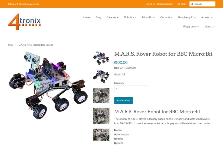
After seeing circuit boards being used as structural members in the 4tronix M.A.R.S. rover, I realized that I had forgotten a very fertile field: LEGO! My interest in mechanical systems today is something I give full credit to the LEGO sets I had growing up. My LEGO creations grew more complex as I grew older, limited only by my toy budget. However, once I got up and running on 3D printing objects of my imaginations, I haven’t touched my big box of LEGO since. I quite enjoy the freedom of not being constrained by what LEGO pieces are available.

Among currently available LEGO sets, there is a tiny little Mars rover as part of the LEGO CITY Mars Research Shuttle (60226). The set is quite affordable, but about the only thing its little rover has resembling Curiosity rover are the number of wheels. Beyond that, there is no rocker-bogie and no corner steering, which is not a surprise at this price point.

Moving up the price and complexity scale is the LEGO NASA Mars Science Laboratory Curiosity Rover (21104), released in 2014 and no longer in production. This was part of the LEGO Ideas program where people can submit their LEGO designs and, if enough other LEGO fans voted in favor, the LEGO group will consider adapting it for production. This particular idea received over 10,000 supporting votes and became an official product. Perusing its assembly instruction PDF, I was surprised to find that this rover has a fully articulating rocker-bogie suspension. Very impressive! I also sadly learned that it required several pieces that I lack in my own LEGO collection, so I couldn’t “just” follow the directions to build one of my own. At some point I could go hunt for the few missing pieces which should be cheaper than buying this out-of-production kit on eBay. People are asking over $100 for a used kit and as much as $1,100 for a never-opened box. That’s more than two Sawppy rovers!

But if price is no object, I can look to other LEGO creations people have posted. There are quite a few “LEGO rover” projects online, and it follows roughly the same trajectory as the past few window shopping posts: most don’t even have six wheels, some have six wheel rocker-bogie but no corner steering, etc.

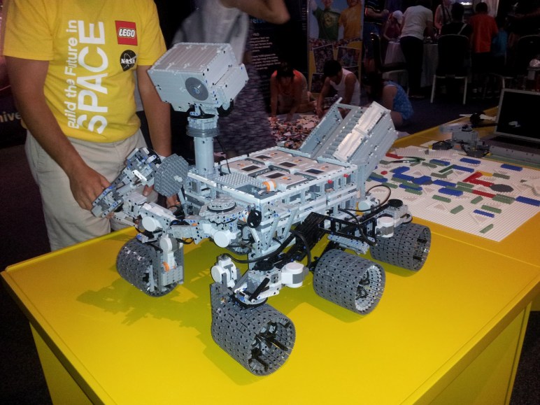
An example of a rover with corner steering is this LEGO MINDSTORM NXT creation. Despite being constrained by the selection of available LEGO pieces, it nevertheless replicated some features that I skipped with my 3D-printed rover. One example being the spokes in each of the six wheels, which I had simplified for 3D printing but the builder here faithfully represented more of the curves. And they have a robot arm, which my Sawppy is still waiting for. But according to the text, only the four corner wheels drive leaving the middle wheels free-wheeling. And it’s not obvious if the rocker-bogie articulates faithfully. At the very minimum, this design is missing the differential bar across the top.

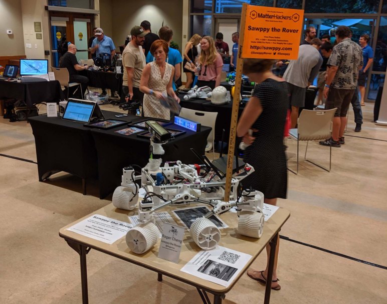
This rover looks to be roughly the same size as my Sawppy rover, but the price tag would be significantly higher. There are six visible NXT brains on this invention: five on board the rover and one for the handheld remote. Each $350 MINDSTORM NXT box comes with a single NXT brain, so this rover costs at a minimum 6 * $350 = $2,100 dollars. Yikes.

So as far as LEGO rovers go, the best ones that implement features I consider important are build-it-yourself designs by enthusiasts and not available as commercial products. Thus we return to the world of 3D printing, where Sawppy isn’t the only rover design floating around.

Window Shopping 4tronix M.A.R.S. Rover

Wheeled robot kits calling themselves rovers are plentiful, but rarely do they faithfully represent the JPL rovers sent to Mars. ServoCity’s Bogie Runt Rover at least is a six-wheel chassis with rocker-bogie suspension, but is missing the corner wheel steering system. Looking for commercially available products out there with six wheel drive rocker-bogie and four corner steering, I was almost ready to conclude none existed until I came across the 4tronix M.A.R.S Rover Robot.

The name is an acronym for Mobile Autonomous Robotic System and the autonomy comes from the brainpower of either a Raspberry Pi Zero or BBC micro:bit. Out of all the commercial products I’ve come across, M.A.R.S. has the most mechanically faithful model of Curiosity and Perseverance suspension geometry. It has roughly similar proportions, and uses a differential arm over the body. Sojourner, Spirit, and Opportunity use a differential inside the body in order to maximize top surface area for solar panels. The nuclear-powered Curiosity and Perseverance didn’t have such constraint. By moving the differential above, they gained body interior volume.

Perusing the assembly instructions I see the structural components are all printed circuit boards (PCB) which is not usually considered structural material but apparently can be made to work at this scale. Six wheel drive comes from N20 micro gear motors, and four wheel steering comes from MG90S metal gear micro servos. Both of these are fairly widely available for maker projects and good choices.

My quibble with the M.A.R.S. rover are with its rotational motion joints. First up are the rocker-bogie suspension components, each of the joints are a M3 screw inside a PCB hole. I’m queasy about using fasteners as axles, since their threads are not really designed to carry a load. There are no bearings on these joints and the screws have to be tightened precisely. Too tight, and the joints would bind. Too loose, and the rover will wobble. This seems awfully finicky and would loosen as the rover travels.

Second, each wheel’s weight is transferred directly into the N20 micro gearbox. Examining pictures of these gearboxes online, it does not appear the gearbox is designed to handle loads perpendicular to rotational axis. Perhaps the rover is lightweight enough the load would be fine, but all I see are metal shafts turning inside holes in brass plate.

And third, each of the corner steering wheel assemblies are attached directly to the steering micro servo’s horn. Despite the metal gears, MG90S type servos still has a great deal of flexibility and play in its gearbox in the face of loads perpendicular to rotational axis. We can see each corner steering assembly wobbling noticeably while in motion:

(I also smiled when I realized this video cuts out right when the rover starts tackling a very challenging vertical climb. We’ll never know if it managed the climb.)

The final quibble I have with this design is that the steering axis is not aligned with the wheel. In less formal terms, it means the wheel is sideways offset from its corresponding steering servo instead of sitting directly under the servo. As a result, when the steering servo rotates, its wheel isn’t pivoting about a point. Instead, it is dragged through an arc. This adds a great deal of mechanical stress to the steering mechanism. It also makes the desired wheel velocity harder to calculate through a turn, but it appears the M.A.R.S. software skips that detail. All left side wheels are commanded to turn at the same rate, and all right side wheels are the same with each other. As a result we can see a bit of wheel skid through a turn, reintroducing some of the problems of using a strictly skid steer system as the Bogie Runt Rover did.

In conclusion M.A.R.S. has the mechanical sophistication of corner steering in addition to a good representation of rocker-bogie suspension, but its current iteration does not yet take full advantage. Still, it looks like a nifty little kit and the price of one hundred pounds is significantly lower than the cost of parts for Sawppy.

This concludes my quick tour of commercially available rover kits. But before I move on to DIY rovers, there’s a rover category that bridges across both “commercial product” and “do it yourself”: LEGO rovers.

Window Shopping ServoCity Bogie Runt Rover

The littleBits Space Rover is a cute little thing, but with only two wheels it bears little resemblance to real life Martian robot explorers. Moving a little bit higher on the fidelity scale, there are some robots out there with six wheels arranged in a rocker-bogie geometry. A representative of this breed is the ServoCity Bogie Runt rover.

Browsing the ServoCity web site, it appears that the Bogie Runt is the largest and most complex (so far?) of their line of “Runt Rover” chassis kits. Peewee, Sprout, and Zip Runt Rovers are two-wheel differential drive chassis like the littleBits Space Rover. Then there are the Junior, Half-Pint, and Whippersnapper Runt Rovers which roll on four wheels. The Bogie Runt is the only one with six wheels, and the only one with an articulating suspension system.

On ServoCity’s “Robot Chassis Kits” page they are all listed under “Smooth Surface.” This is certainly true for all the other Runt Rovers, but the Bogie Runt should be able to handle rougher terrain thanks to the rocker-bogie suspension system. It’s not obvious if the smooth surface classification for Bogie Runt was a mistake, or if it was deliberate based on information not immediately visible from just window shopping.

All of the Runt Rover kits appear to be made by laser (or possibly waterjet) cutting of flat materials, likely some type of plastic. They have bolt patterns to connect with ServoCity’s Actobotics build system which is mostly aluminum. Actobotics is very popular with FIRST Robotics participants and because of that, it was also the build system selected for the JPL Open Source Rover.

But that also causes a problem I have with the Bogie Runt: Actobotics is based on Inch dimensions and thus problematic for use outside of the United States. Sawppy is metric and, for worldwide compatibility, I plan to keep all derivatives and descendants metric.

Another shortfall of Bogie Runt is the lack of corner steering mechanisms. It is thus constrained to differential drive (a.k.a. “Tank Steer”) which works very well for two wheels but precision drops as the number of contact patches go up. In my experience, differential drive is marginal for four wheels, and behaves unpredictably with six. It was a tradeoff the Bogie Runt Rover product made against cost and complexity, leaving room for improvement and motivation for me to keep looking.

Window Shopping littleBits Space Rover Inventor Kit

Before I start getting too ambitious with making my personal rover project more like a user-friendly commercial product, I should look around to see if a product already existed. There are a lot of robot kits out there trying to earn that STEM education money, and some of them do try to get a slice of the excitement around our interplanetary robotic explorers. And while some of them are interesting and have their own merits, most of them lack features that I consider critical in a rover relative.

A representative example is the Space Rover Inventor Kit from littleBits. I like the idea of littleBits, giving beginners a very friendly way to explore electronics by making components with magnetic connectors. This makes electrical connections easy and also helps avoid beginner mistakes like accidentally reversing electrical polarity. The downside is that the customer has to pay a premium for this capability, and it’s not a premium that I’ve been personally willing to pay. This particular kit has a MSRP of $200 USD, and for that kind of money I would much rather build my own robot. (Though at time of this posting, the kit is on sale for $30.)

As a supplement to generic electronics beginner kits, littleBits also apply their technology to some themed offerings like this Space Rover kit. All the electrical components are reusable and remixable littleBits centered around a robot control module. The module is interesting because it interacts with a phone app, giving the rover remote control capabilities. But I also see the app as a disadvantage: as I understand it, the app would discourage experimentation. If the user changes the rover around, it wouldn’t take much before it exceeds what the phone app can gracefully handle. Thus motivating the user to leave it in the space rover configuration, defeating the point of using littleBits to begin with.

But in my eyes the biggest shortfall of this rover is its two-wheeled differential drive chassis. Similar to what home robot vacuums like Roomba uses. This is fine for flat indoor ground, which is what earthbound rovers mostly end up doing anyway. So as a home education toy this is a good technical choice. But for fans of rocker-bogie like myself, this is sorely lacking and we must look elsewhere.

But at least this little Space Rover has an arm. Looks like it only has one degree of freedom, which is very limiting, but that’s one more degree of freedom than Sawppy’s nonexistent robot arm. Victory: littleBits Space Rover!

Sawppy Cost and Complexity

Sawppy is just like every other project in that there’s a long list of ideas of things to do. I’ve been blabbing here for a while about problems and ideas to fix them, most recently about how hard it is to carry Sawppy around. But all those ideas have to balance the benefit against cost. Not just in terms of money, but also in terms of construction complexity.

I designed and built Sawppy as a lower-cost alternative to the JPL Open Source Rover, giving up on capabilities in exchange for a lower monetary barrier to entry. Using serial bus servos allowed a much simpler electrical system, though they contributed problems of their own. Mechanically, the construction complexity of both rovers are not very far apart in no small part to the large number of fasteners in both designs.

This was because my primary audience for Sawppy was myself, and I aimed at my own strengths and avoided my weaknesses like wiring. This was fine for the rover builders out there who have similar or superior skills, but it left out people who want a rover but didn’t have the same background. I know of rover builders who were stuck on the software, or on the electrical, or 3D-printed all the parts but never found the time to go through the time-consuming process of putting everything together.

Some people who didn’t have the same skills and background as I did found my Sawppy documentation lacking. Most were apologetic as they asked for help, others were… less polite. One notable person was unhappy that I didn’t provide detailed electrical wiring schematics and blasted the project for it. Dude… I give Sawppy out for free, if you’re unhappy I’ll refund your $0. Piss off.

Rude self-entitled people aside, there is clearly an unmet need. Sawppy was designed for people who are likely to tinker and modify my design, so many things were left loose and open to interpretation and customization. The freedom of choice can be disorienting for some, so there are people who would appreciate a rover that is not only cheaper and simpler to build, but also a corresponding set of prescriptive step-by-step directions to get there.

This starts to sound like what people expect in a commercial product. And there are a few already out there. So what ground have already been covered, and what can I do that’ll be different? It’s time to window shop a few products, starting with the littleBits Space Rover.

[Headline image: Sawppy at MatterHackers Modern Creators event. Behind Sawppy is Tamara @tlynnr85 promoting her Seekers of Science project.]

Sawppy Issue: Portability

Sawppy’s top speed is approximately 40 times faster than the scaled top speed of Curiosity rover. Even then, it is the pace of a very slow walk and I frequently pick up my rover to walk faster. Which leads to the next problem: there’s no good way to carry Sawppy. The cool rocker-bogie suspension gets in the way of using any piece of aluminum extrusion beam as a carry handle, and even when I try to do so, Sawppy looks really undignified when carried that way. It looks better for me to slide my arms under the main body and lift. Sawppy remains upright, but my arms get tired very quickly. And the dangling rocker-bogie still keep bumping into things.

Sawppy is also pretty awkward when I need to carry further than walking distance. I built Sawppy to be roughly the same size as the JPL Open Source Rover, but more precisely I built Sawppy to be roughly the largest size that I can still carry in my car. I’m not ready to buy a larger vehicle for the sake of carrying a rover.

For walkable distances, SGVHAK rover is ferried about by a collapsible wagon. I thought that would be a good idea for Sawppy but have yet to get one of my own. And that still doesn’t solve the problem of taking up a lot of space in a car.

The real Mars rovers have a provision to fold up compactly for their journey to Mars. The tall camera mast folds down, and so does the rocker-bogie suspension. Sawppy has not duplicated either of these capabilities, and I think it might be time for Sawppy to learn to be a little more flexible for long trips. Thanks to some helpful friend-of-friends networking, I found out that the suspension folding mechanism is the “Rocker Deploy Pivot”. (Thank you, @LongHairNasaGuy) Knowing the official terminology is the key to start researching for more details. Studying the real thing aids contemplation for adapting a simplified form for Sawppy.

For walking distance trips, several options are possible. I could get a wagon like the one for SGVHAK rover, or I could build some kind of a skateboard for Sawppy to ride. I should also think about adding a carrying handle to Sawppy somewhere. So many things I can add to Sawppy, but doing too much risks making an overly complicated rover.

Sawppy Is Both Too Fast And Not Fast Enough

Sawppy was designed to be a motorized scale model of Mars rover Curiosity and Perseverance that faithfully replicates their rocker-bogie suspension geometry and articulation, which is really cool for rough terrain but overly complicated for flat ground. Sawppy also have wheels heavily inspired by Perseverance, which is designed for Mars but rather less great here on planet Earth.

Rolling around on those wheels is a signification deviation from source material. Sawppy crawls around fairly slowly, just under 40 centimeters per second. This is roughly the speed of a toddler learning to walk. But even that is far faster than scale speed. Curiosity has a maximum speed of four centimeters per second (0.144 km/hr or 0.089 MPH.) Sawppy is roughly quarter scale, so matching scale means rolling with a maximum speed of one centimeter per second, just barely faster than a snail. On Mars there’s not much of an incentive to hurry and the robot explorers can take their time. Here on Earth we have no patience for that kind of speed and hyperactive kids would quickly lose interest.

The target speed is also reflected in the suspension geometry. A Mars rover would never go fast enough to catch some air, and thus would not need the ability to absorb impact of landing. My Sawppy going 40 cm/s is not a lot of stress, but anyone hoping to build Sawppy into a high speed dune buggy will be sorely disappointed. Bob Krause of Inventor Studios coaches a FIRST Robotics team, and they investigated adapting Sawppy to be their competition robot. Given the drastically different design constraints between Mars exploration and FIRST Robotics, they concluded this suspension design is the wrong choice for a competition where speed is essential, and I agree.

Because for all practical purposes, Sawppy’s “40X scale speed” is still too darned slow. The speed is fine when I’m doing something like casually cruising a Maker Faire looking at all the exhibit booths. But if I am on a schedule and have somewhere to be, I end up picking up Sawppy to carry by hand.

Sawppy Wheel Traction Has Downsides And Upsides

Sawppy copied the rocker-bogie suspension system from Mars rovers Curiosity and Perseverance, who are destined to roam Martian terrain. But Sawppy on Earth mostly roamed flat ground instead of uneven terrain. This made the suspension largely superfluous except for contrived demonstrations, adding complexity and weight that is not strictly necessary. But I love it anyway, as a tribute to our Martian robotic explorers.

Another tradeoff Sawppy inherited from the big rovers are the wheels. Sawppy’s wheels surfaces are designed to mimic that of Perseverance rover. Grousers (raised ribs on the surface) designed to scrabble over sand and rock struggle to find grip on asphalt or concrete. This is not a problem for Curiosity and Perseverance as there is no asphalt or concrete (or carpet, or tile…) on Mars. But Sawppy struggles on made-for-human interiors.

Most wheeled vehicles on Earth use rubber tires of some type for traction. Many different varieties are available, optimized for different surfaces. Mars rovers do not use rubber tires because rubber (both natural and synthetic) would quickly break down in the Martian atmosphere. They are also quite heavy, and weight is a constant enemy for anything launched into space. Which is why Martian rover wheels are lightweight thin-shelled metal constructs designed just tough enough to handle all known Martian terrain. Unfortunately, Curiosity’s wheels have been torn up by some unknown Martian terrain. Lessons learned from engineering tests led to redesigned wheels on Perseverance that should better handle its voyage.

But none of that are of concern for Sawppy rovers here on Earth, so various rover builders have explored improving wheel traction. Chris Bond replaced the wheels with RC monster truck wheels, similar to those on JPL Open Source Rover. Steve’s Tenacity rover got some rubbery overshoe to fit over standard Sawppy wheels.

But increasing traction could also magnify other problems making them worse. With my wheels, a Sawppy rover can be tolerant of minor steering angle misalignment, the wheel will just slip sideways a bit as it rolls. With high-traction wheels, steering angle misalignment would start pulling the wheel towards/push it away from the body, twisting the suspension geometry. This has proven to be a problem with JPL Open Source Rovers and their high traction rubber tires. This is not very noticeable when driving short distances, but minor steering alignment eventually become a big problem for longer drives.

Sawppy Issue: Terrain Mismatch

Backing off from specific design issues like steering trim adjustment, I want to note a general problem with public demonstrations. Sawppy is an approximately 1/4 scale model of Mars rovers Curiosity and Perseverance, faithfully replicating the geometry and articulation of their rocker-bogie suspension systems designed for traversing Martian terrain. Down here on planet Earth, Sawppy has historically not spent much time rolling on Mars-analogue terrain. Most of the time, when I take Sawppy out for show-and-tell, my rover is rolling on surfaces like asphalt, concrete, carpet, hardwood, or tile.

Mars doesn’t have any of those surfaces. With such luxuriously flat and smooth environments, there’s not much opportunity for Sawppy to show off how nifty a rocker-bogie suspension is. I found myself manufacturing challenges out of what’s on hand, which is why instead of sandy dunes or rocky fields, Sawppy finds itself running over feet…

… and backpacks.

Fundamentally, Sawppy is out of its element on smooth terrain. Robots optimized for flat ground would not need the capabilities of a rocker-bogie suspension system, where it is far more complex and heavy than required for the circumstances. But every once in a while, a Sawppy rover gets to visit a someplace resembling its natural habitat, such as when Aussie Sawppy took a trip to the beach.

This is the kind of terrain the rocker-bogie suspension — and the wheels — are designed for.

Sawppy Issue: Steering Angle Adjustment

I haven’t heard much feedback on the next topic, this is mostly my experience with my own Sawppy. The root cause here are the output shaft angle sensors used in inexpensive servo motors such as the LewanSoul/HiWonder LX-16A serial bus servos used on my rover. For the most part, they are just inexpensive potentiometers, and they are not terribly consistent. In practice, this means steering angles on each of Sawppy’s four corner steering servos are a little different for every Sawppy driving session. I don’t know all the variables involved, there’s probably some combination of temperature, humidity, or maybe even the phase of the moon. Who knows?

One solution is to buy better components with precision angle sensors. But since an overriding goal of the project is to keep the rover affordable and accessible, I’m going to resist going down that path as much as I can.

Sawppy was designed with a way to adjust steering center angle. What I had in mind were the set screws and where they dug into the steering shaft, which would have been a relatively unmoving thing. So Sawppy steering trim is adjusted by the rover chassis configuration file that is loaded by the software at bootup. This would have been fine if it was something a rover builder only had to do once when building the rover. I did not anticipate steering would fall out of trim on a recurring basis, and requiring this file be edited for every driving session is a huge hassle.

SGVHAK rover also had a trim adjustment issue. That rover’s steering motors had relative encoders but had no homing reference point so it didn’t know where “straight ahead” was upon bootup. Since I expected it to have to be adjusted on every startup, I added a menu in software to perform steering trim adjustment. This is friendlier than a configuration text file, but it was a multi-step process that takes at least thirty seconds per corner. I still consider that too much work.

For a future rover revision, I intend to add some mechanical mean to compensate for drifting potentiometers. I want to loosen something (using screwdriver, or wrench, or even a tool-less contraption if I’m clever) to release the corner steering mechanism, steer the wheel by hand to desired alignment, and tighten things back down. Ideally I want to adjust the steering angle in under 10 seconds per corner.

The JPL Open Source Rover uses high quality (and expensive!) steering angle sensors. The sensor angles have no such drift to speak of, but the steering shafts do sometimes slip inside their steering couplers resulting again in misaligned wheels. Fortunately, these sensors are easily accessible and with a crescent wrench I could turn the sensor inside their mounted position to adjust trim. This is the kind of adjustment I want.

I have a very crude equivalent for Sawppy right now. Sometimes I have an emergency and need to adjust steering trim in a hurry. I can loosen the set screw in the steering servo coupler, steer the wheel manually, and tighten that set screw back down. This only worked because the set screws I bought from McMaster-Carr are much harder than steering shaft material, so tightening it would dig a new hole at the desired position. But I could only do this a limited number of times before the shaft is too chewed up to hold any angle and I need to cut a new shaft.

But it taught me that a mechanical steering trim adjustment mechanism is fast and easy to use. I just need to find a way to preserve that user experience in a more well-thought and more enduring design. Even if Sawppy’s suspension system is rather underutilized most of the time.

Sawppy Issue: Serial Bus Servo

I was surprised when I learned Misumi aluminum extrusions weren’t as easily available as I had originally thought. I was less surprised to learn that serial bus servos were a problem as well. When I started the project I knew they were on the rare side but thought it was worth a shot. I’m still a fan and stand by everything in my Hackaday overview, but I admit spotty worldwide availability is only the first of many problems.

Even when serial bus servos are available, the selection of sizes and capabilities is limited relative to more common motors. If someone wanted to make a small Sawppy like Dean, or a big Sawppy like Quinn, it’s hard to find serial bus servos of the appropriate size. And even if serial bus servos can be found in the right size, the communication protocol is not standardized. Dean has yet to figure out the protocol for the tiny servos he found. And then there’s the software side of the problem, where each protocol needs corresponding code written for Sawppy’s brain.

Another problem is that their position feedback has been disappointingly limited, at least in the LewanSoul/Hiwonder LX-16A servos on my own Sawppy. They could turn a full 360 degrees, but only return reliable position data for ~240 degrees within that range. That makes it difficult to calculate wheel odometry. Rhys Mainwaring tackled this problem with the Curio rover software stack, but no matter how good the extrapolation code works it’s not as good as actual data. I think my effort to do things on the cheap did not pan out and, if a robot wants wheel odometry, we have to go to real wheel encoders separate from the drive motor. Marco Walther (mw46d)’s Sawppy wheel modification sets a precedent on how this might be done.

Thanks to feedback from fellow rover fans around the world, I have since learned serial bus servos are not the best choice for a project that I intended for people to build around the world. I should fall back to more common components like RC servos and DC motors. But whatever is ultimately used as the steering actuator, I want to improve how steering angle is adjusted.

Sawppy Issue: Misumi Aluminum Extrusions

Sawppy has hundreds of fasteners to hold 3D-printed parts on aluminum extrusion beams. Managing all those fasteners has turned out to be a chore and it is something I want to improve in a future revision. While I’m reconsidering those fasteners, the extrusion beams are worth a bit of thought as well.

I designed Sawppy around extrusion beams with a 15mm square profile, chosen because it felt like roughly the right size to stay proportional to the real Mars rovers. Designing in metric was an intentional choice to make it friendlier worldwide. This was in response to chatter on the JPL Open Source Rover forums, where its non-metric parts caused headaches for builders outside of the United States.

The aluminum beams in my own Sawppy was purchased from Misumi USA. I chose their 15mm HFS3 series because the slots were cut in a way that permitted the option to use commodity M3 nuts instead of their specialty HFS3 nuts. Another reason for choosing Misumi was that they are a global company with distributors around the world, making HFS3 available worldwide.

After I published Sawppy instructions online, I started receiving feedback from builders outside of the United States and learned of a catch: while Misumi USA is happy to sell to anyone with a credit card, other Misumi distributors around the world are not so hobbyist friendly. Misumi Europe, for example, deals only with businesses and is not interested in earning income from hobbyists.

Fortunately resourceful hackers in Europe quickly found that the MakerBeam XL is a direct substitute and there are hobbyist-friendly distributors in Europe. It is more expensive, but at least it is available, and several European Sawppy rovers were built with it.

Aussie Sawppy, on the other hand, had none of those options domestically. So 15mm extrusions were ordered from China. That rover had to wait a long time for parts to arrive, but at least it is an option. There are a few countries where prohibitive import duties make even that impractical. I’ve heard from two aspiring rover builders in Argentina who will try to build a Sawppy using rectangular profile metal tubes.

I think aluminum extrusion beams are still the way to go for a Sawppy-sized project. And thanks to the availability of MakerBeam XL and AliExpress, staying with existing 15mm profile is still a good option. However, I am contemplating a move up to 20mm square profile. They’ll make the rover look a little bulkier, but 20mm is far more common worldwide than 15mm. If nothing else, 20mm extrusion beams are popular in maker circles due to a large number of popular 3D printers built with them like the Creality Ender 3. If I move up to 20mm there is a long term possibility for a rover built from chassis beams of retired 3D printers. Based on feedback I’ve received, moving away from 15mm extrusion beams and serial bus servos for Sawppy V2 would help mitigate two of the biggest problems with worldwide availability of Sawppy parts.

Sawppy Issue: Fastener Overload

I wanted keep the barrier of entry for Sawppy low. Make it accessible to rover fans worldwide. In hindsight a few of the tradeoffs I made for this goal did not pan out. Some of these were a consequence of wanting to make sure Sawppy could be built with only handheld tools. It turns ensuring proper shaft alignment requires a drill press. A drill press is also potentially useful for greatly simplifying Sawppy construction.

There are a lot of M3 fasteners used all over Sawppy. Literally hundreds of M3 bolts, nuts, and washers. The original idea was to have a system that allows for easy experimentation. M3 nuts can slide all along these extrusions, allowing rover builders to experiment with different suspension geometries and attach modifications. But in my own experience, having so many fasteners made every modification a huge hassle. Even changing one little thing might involve tens of fasteners. The tedium of tending to those fasteners discouraged me from doing as much experimentation as I originally thought I would, defeating the original intent.

There is another approach to building with extrusion beams, and that is to drill holes for larger fasteners to pass through the hole to a nut or something on the other side. There are two downsides to this approach. The first is loss of flexibility as the hole position is permanent. The second is that drilling a hole through the center of an extrusion beam requires holding the drill bit steady even as it catches on the edges of extrusion rails. I have never successfully done this with a handheld drill, I could only do it with the help of a vise holding the extrusion beam in place under a drill press.

So I avoided this construction method because I didn’t want to require people to have access to a drill press and vise. In light of my experience to date with Sawppy, however, I have changed my mind on this topic. While imposing a drill press + vise requirement would push Sawppy out of reach of some hypothetical aspiring rover builders, I noticed that almost every Sawppy builder I’ve corresponded with have such access and it wouldn’t have been a barrier for them. As for the people that don’t have access to such equipment, they still have the option of building Sawppy V1.

Given that I’m reconsidering how Sawppy components will fasten to extrusion beams, it is also a good time to think about the beams themselves.

Sawppy Issue: 8mm Hole Precision

The old mechanical adage is that anything that moves is a potential point of failure, and Sawppy is not immune. Every point of rotational motion uses 8mm steel shafts and they have proven to be challenging for myself and other rover builders. They are kept in location by E-clips, and cutting precise slots for them are hard without a metalworking lathe. For pieces that need to grip on those shafts, my designed used M3 set screws that pushes against plastic with the help of heat-set inserts. And getting them right can also be frustrating.

For pieces of plastic that don’t need to grip on the shaft with set screws, they should still have a snug fit. But 3D printing a precise diameter hole is hard to accomplish given variances of 3D printers. Not just variation from printer to printer, but that a printer may have difficulty hitting the same exact XY coordinates on every print layer to line up a precise hole.

Fortunately this is a problem with an existing solution from the world of machining. When a precise diameter is required, rotational cutting tools called reamers are used. Sawppy’s instructions included use of an 8mm reamer to make precise holes that will fit tightly onto 8mm shafts, and a reamer built for metal had no problems chewing through thermoplastic.

But I found that wasn’t the end of the story, because a reamer only helps make the diameter precise. The location is only as precise as the drill turning the reamer. I had naively thought the reamer would be guided to the correct location and alignment by the existing 3D-printed hole. It did to some extent, but not enough to ensure precision. If the drill is positioned off-center or tilted off-axis, my reamer happily reamed out an off-center, off-axis hole of very precise diameter.

What happens when the hole position or tilt is wrong? In case of suspension components, the articulation will change by a few degrees. In case of wheels, it means the center of rotation would be slightly offset from wheel center. When such wheels spin up, they will visibly wobble. Actually neither would be a functional blocker for Sawppy, as the rocker-bogie suspension can tolerate these variations and keep all six wheels on the ground. But it does look a little silly and drive perfectionists mad.

I don’t think there’s any way to solve the off-tilt problem for handheld drills. Every solution I thought of to hold the drill in alignment ends up looking like a drill press. Why reinvent this wheel? Unfortunately that’s a piece of shop equipment not every aspiring rover builder owns.

The off-center problem is harder to solve. Right now my train of thought is heading towards some kind of centering jig. The challenge is to design something that can be 3D-printed yet help deliver higher precision than what 3D-printing can deliver on its own. Can it be done? I don’t know, but I’m thinking about it.

Back on the topic of drill press: there is a second reason why I might want to make them part of the Sawppy builder’s toolkit: a drill press would allow me to drastically reduce the number of fasteners required to build Sawppy.

Sawppy Issue: Getting E-Clip Slots Right Is Hard

Closely related to the challenging heat-set inserts are the shafts their set screws bite into. I designed Sawppy to use 8mm metal shafts everywhere there is rotational motion: for wheel rolling, wheel steering, and rocker-bogie suspension articulation. Generally speaking there are three steps to fabricate Sawppy shafts:

  1. Cut to the proper length.
  2. Cut slots for E-rings.
  3. Cut flats for set screws. (For some of them.)

And it turns out the E-clips make everything trickier than it really needed to be. Unlike my ignorance with heat-set inserts, I knew E-clips are not very standardized, especially in their thickness. So my documentation couldn’t really say what the proper lengths would be, I could only give the functional dimensions and tell people to add width of their E-clip slots.

For cutting those E-clip slots themselves, I documented a “Poor Man’s Lathe” technique using two motorized tools, but this is not very precise. Fortunately, high precision is not required for a 3D-printed rover, the worst thing that happens is a rover whose suspension is a little bit wobblier than it would otherwise be.

Being a perfectionist, I was not happy with the hand-built results and arranged to cut a second set of Sawppy shafts with a manually operated metalworking lathe. And I knew imprecision would bother other Sawppy builders out there as well and not everyone could get access to a real lathe.

In the meantime, people have devised other workarounds. Ameer used M8 bolts and nuts instead. Using threaded fasteners instead of a solid shaft would put stress on the threads, but probably not terribly much for a little 3D printed rover. And it is definitely easier to work with.

The challenge with this approach is in tightening these bolts. If they are too loose, rover suspension will wobble and we’ve gained nothing. But if they are too tight, it puts too much axial load on the bearings and they seize up instead of turning freely as they should. I think there is a better way down the fastener path, and have a few ideas to test. If successful, a future Sawppy would use fasteners instead of fabricating shafts and also not unduly stress its threads or be finicky about amount of tightening torque.

I don’t like it when some part of Sawppy is finicky, but I’ve come to accept that a tradeoff has to be made between finicky precision and a design that can be built by the widest range of rover enthusiasts. This became the most apparent when dealing with holes for these 8mm shafts.

Sawppy Issue: Heat Set Insert Shaft Coupling

Looking at what other Sawppy builders have done to customize their own rovers, I learned that ground clearance isn’t as valued as I thought it would be. At first I was disappointed, because giving Sawppy great ground clearance took a lot of hard work. But then I decided to look on the positive side, because this feedback also meant I could trade off some clearance for other features and not have it be considered an instant fail.

Another common theme of feedback on Sawppy wheels concern shaft coupling and heat-set inserts. It has been a perpetual problem for me, to the point where I started preparing field replacement units of shaft couplers. I also heard from other Sawppy builders that it has been problematic for them as well.

The biggest problem was caused by my ignorance: I thought all M3 inserts would be the same size, but I was wrong. Inside, yes, but not outside. Furthermore, optimal heat set inserts usage require hole diameter within a pretty narrow range. And that range appears to be narrower than the range of variation between 3D printers. All this meant my Sawppy design printed as-is would frequently not work for another rover builder and require modification. Either their insert is a different diameter, or their printer would print differently, or some combination of both.

Some builders applied their creativity to this problem and came up with alternate approaches. Chris Bond went with the direct approach: drilling and tapping a hole through the diameter of the shaft. This is a good option if a vise and drill press is available, but drilling on a round shape is very challenging with handheld tools.

TeamSG for Aussie Sawppy explored another route: instead of round shafts, use hex profile shafts. I knew precision shaped profile beams of metal are expensive and difficult to get, so I didn’t think it was a good idea. But TeamSG thought of something I did not: Hex profile wrenches are plentiful, precise, and made of strong metals. Cutting up a few is a brilliant approach to build some rover hex drives!

Laura McKeegan’s CJ rover offered yet another approach: use captive hex nuts which worked when heat-set inserts did not. Unlike heat-set inserts, M3 hex nuts are standardized with an external diameter of 5.5mm from flat to flat.

My own experiments with captive nuts have not been successful, because if I put too much force my nuts will start spinning inside their slot. To fix this, I would heat it up with my soldering iron and turn it into a crude heat-set insert. So I thought I’d just go straight to heat-set inserts. But given feedback from builders and knowing what I know now about non-uniformity of M3 heat set inserts, I think captive nuts might be worth another look.

And while I’m working on solutions for Sawppy’s shaft coupler problems, it’s worth noting that the shaft themselves have been problematic as well.

The Less Famous Rovers Marie Curie, Dusty, and Maggie

While I’m on the subject of rover suspension and ground clearance, I want to take a detour to recognize the less famous rovers that didn’t make the trip to Mars. My rover fandom has mostly been focused on siblings Curiosity and Perseverance, but those rovers would not exist if it weren’t for the twin rovers Spirit and Opportunity. Formally the Mars Exploration Rover program, they followed Sojourner the rover technology demonstrator. Each rover generation was larger and more sophisticated than the last, but one thing all those rovers had in common was the rocker-bogie suspension design that I replicated with my own Sawppy rover using references like a rover family portrait published by NASA.

But the real rovers are on Mars. Who are the rovers in this picture? The little one is named Marie Curie, and is a “Flight Spare” for Sojourner (Truth). Meaning it is fully equipped and qualified to be sent to Mars as an alternate if necessary, but there was no need so Marie Curie stayed on Earth. I assume it played a role during the mission as a testbed as the other two rovers did.

Representing Spirit and Opportunity is the MER Surface System Test Bed. This rover duplicates many of the mechanicals of Spirit and Opportunity, but is not fully equipped to go to Mars. For one thing, it runs on a power tether and have no functioning solar panels, just passive stand-ins. This machine stayed at JPL’s Mars Yard to help scientists and engineers on Earth test ideas and solutions before commands are sent to Mars.

MER SSTB is a mouthful, and I remember seeing JPL people on Twitter calling the test rover “Dusty” but I found no official confirmation of this name. After the Mars Exploration Rover program ended, Dusty(?) was given to the Smithsonian where it will continue to represent the MER program when put on display.

The Mars Science Laboratory (MSL) mission included the Earthbound Vehicle System Test Bed counterpart to Curiosity shown in the family photo, again with some differences such as powered by a tether instead of faithfully duplicating an onboard radio-thermal nuclear reactor. According to this article, the MSL VSTB counterpart to Curiosity is “Maggie”, and the Mars 2020 test bed counterpart to Perseverance is “Optimism”.

And since these are engineering tools, both names are officially engineering acronyms. Or more likely, “backronyms” where the acronym was chosen first, then words were chosen to fit it. That’s why we have convoluted names like “Mars Automated Giant Gizmo for Integrated Engineering” and “Operational Perseverance Twin for Integration of Mechanisms and Instruments Sent to Mars.”

These rovers won’t get nearly as much fame as their Mars-bound counterparts, but they all play vital roles contributing to mission success.

[Image credit: NASA/JPL-Caltech]

Sawppy Rover Ground Clearance

When it comes time for Ingenuity to demonstrate Mars helicopter technology, it will be dropped to the surface then wait for Perseverance to move a small distance away to prepare for the experiment. This arrangement is possible because the rover’s rocker-bogie suspension gave it more than enough ground clearance for a hitchhiking helicopter to ride along, holding on to the belly of the rover.

This ample ground clearance is also visible in the Mars 2020 Mission Identifier. The first I saw of this logo was on the side of the rocket payload aerodynamic fairing protecting the rover against the atmosphere during launch. I love this blocky minimalist design of the rover’s front view and believe this little logo hasn’t been used nearly enough.

Anyway, back to ground clearance: it is something obviously useful for a wheeled vehicle traversing off-road, which is desirable given the lack of roads on Mars. But raising the height of rover’s main body is only part of the equation, because it’s not the only thing that might collide with obstacles on the ground. We also have to worry about suspension components. This is something I noticed with JPL’s Open Source Rover design: if a ground obstacle is offset from a wheel, there’s a chance it will collide with aluminum structure. This picture uses a Roomba virtual wall marker to represent a rock on the ground, which is about to collide with suspension structure:

When I designed Sawppy, I thought I could improve upon this specific issue by taking advantage of the flexibility of 3D printing. I also chose Sawppy wheel motors with the requirement they must fit within the wheel with no protrusions. If Sawppy should encounter a Roomba virtual wall marker slightly offset from a wheel, there is no risk of collision:

I this was a pretty good Sawppy feature. However, after looking at how other Sawppy builders have customized their rovers, it appears this feature isn’t as valued as I thought it would be. There have been many Sawppy modifications that did not preserve this clearance.

For example, Marco Walther [mw46d] replaced wheel motors with much longer units that risks collision. He is aware of the risk, because he designed shielding to protect the motor encoders from damage. It’s a different approach, shielding vs. avoidance. Steve [jetdillo] adopted Marco’s design to good effect.

Chris Bond swapped out the wheels for RC monster truck wheels, similar to those used by JPL Open Source Rover. However, my wheel mounting arm design does not fit within the wheel. To compensate for this, Chris decided to push the wheels out. This leaves almost the entire wheel mounting arm out where it could collide with ground obstacles. It also means the steering axis is no longer aligned with the wheel, but Chris seems happy with his design so I guess it works well enough.

My lesson is that ground clearance isn’t as important as I thought it was. Or at least, not seen as important enough relative to features other builders wanted for their own rovers. This is valuable feedback for future iterations.

On the topic of rover iterations, I want to take a quick detour from my own rover to recognize some lesser-known counterparts to our robotic Mars explorers before returning to the topic of Sawppy builder feedback.

Ingenuity the Mars Helicopter Technology Demonstrator

One of the most exciting part of the Mars 2020 mission is not visible on the Perseverance rover interactive 3D web page. It is Ingenuity, officially named the Mars Helicopter Technology Demonstrator. (It has its own online interactive 3D model.) For people like myself who want to really dig into the technical details, NASA JPL published many papers on the project including this one for the 2018 AIAA Atmospheric Flight Mechanics Conference. (DOI: 10.2514/6.2018-0023)

Ingenuity is the latest in a long line of technology demonstrator projects from JPL, where ideas are tested at a small scale in a noncritical capacity. Once proven, later missions can make more extensive use of the technology. Perseverance rover itself is part of such a line, tracing back to Sojourner which was the technology demonstrator for the concept of a Mars rover. Reflected in its official name, the Microrover Flight Experiment.

Most of the popular press has covered Ingenuity’s rotors and how they had to be designed for Mars. It has the advantage that it only had to lift against Martian gravity, which is much weaker than Earth gravity. But that advantage is more than balanced out by the disadvantage of having to work in Martian atmosphere, which is much much thinner than Earth air. Designing and testing them on Earth was a pretty significant challenge.

Mechanically, the part I find the most interesting were motor and control system for the coaxial helicopter. It has been simplified relative to coaxial helicopters flying on Earth, but still far more complex than the category of multirotor aircraft commonly called drones. Most multirotor aircraft have no mechanical control linkages at all, their propellers rigidly attached to a motor and control is strictly electronic via motor power. The paper describes the challenges of implementing a coaxial helicopter control system for Mars, but it didn’t explain why the design was chosen in the first place. I’m sure someone worked through the tradeoffs. Since mechanical simplicity (and hence reliability) is highly valued in planetary missions, I am very curious what factors outweighed it. Perhaps that information was published in another paper?

Electronically, the most exciting thing is Ingenuity’s brain, which is from the Snapdragon line of processors better known as the brains for cell phones and tablets here on Earth. If it works on Mars, it would offer a huge increase in computing power for planetary missions. Perseverance itself runs on a RAD750 computer, which has proven its reliability through many successful spacecraft but is roughly equivalent to a 20-year old PowerPC desktop. Having more powerful CPUs for future missions will allow our robotic explorers to be more autonomous instead of being dependent on brains back here on Earth to tell them what to do.

Perseverance Rover Interactive 3D Model

NASA released a 3D printable static display model of Mars rover Perseverance, which seems to have some improvements over the earlier Curiosity model. But that’s not the only 3D resource for the rover currently on its way to Mars. There is also a version designed for on-screen display rather than 3D printing.

Both the 3D printable (in STL file format) and 3D render (GLB file format) models were listed on the Mars 2020 rover page, which as of this writing has curiosity disappeared from the index page of NASA 3D resources. I’m not sure what’s going on there, but hopefully it’ll be fixed shortly.

When I listed 3D resources for Curiosity there was also a model suitable for 3D rendering. Available as download files for Blender the open source 3D graphics tool and as files embedded in a web page for interactive viewing. The latter is again available: The Mars 2020 mission page has a 3D model of Perseverance that we can interact within a web browser.

This browser interactive model is the most easily accessible version, there’s no need to install Blender or any other piece of software. It serves as an index page to many other pieces of information talking about the rover. While it has a lot of detail missing from the 3D printable model, it still has a few minor flaws. One of them I noticed only because I’ve been a fanatic of the rover: the online interactive rover’s right side wheels are reversed from the actual rover.

Perseverance, like Curiosity before it, has wheel spokes that are curved to absorb impact. I simplified the idea and translated it into a 3D-printable shape for Sawppy’s wheel. For both rovers, the direction of curvature for wheel spokes are the same for all six wheels, clearly visible in rover test footage. Shot in JPL’s vehicle assembly bay, we can see that the wheel spoke curvature is “clockwise” on all six wheels of Curiosity and Perseverance.

On the online interactive 3D model, its left side wheels match the real rover but its right side wheels had been flipped so the spokes point counter-clockwise.

It’s a tiny detail that would only be noticed by the most particular of rover fans, which I certainly am. Surprisingly, I’m not the only one! Because I’ve received questions about whether Sawppy’s wheels should be printed in mirrored orientation. Some Sawppy builders choose as I did, to have six identical wheels matching the real rover. Others chose to mirror three of the wheels as the web page interactive model did.

UPDATE: As one of the items leading up to (successful!) landing, the power team responsible for the radioisotope thermoelectric generator posted a different browser interactive 3D model online. This model is tailored more for engineering information than looking good, with components in false colors for contrast. But it is FAR more detailed, including wiring harnesses for wheel drive and steering motors. It also wins on accuracy in my book, as I see the wheel spokes are pointing in the correct direction.

And an extra bonus on this version: it includes Ingenuity, the first aircraft built by humans to fly in the atmosphere of another planet.