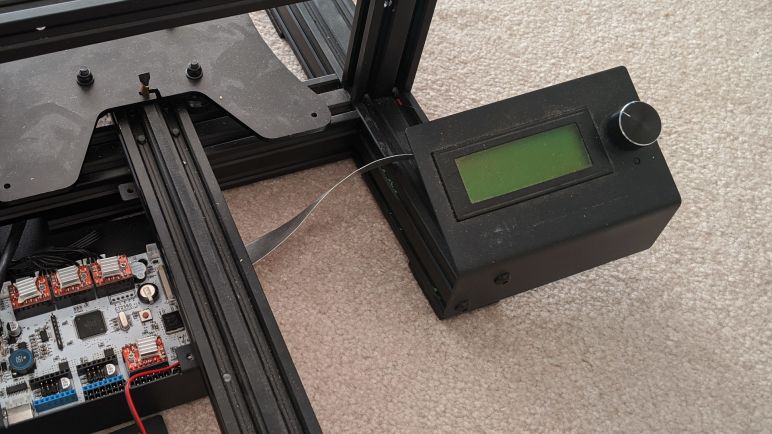
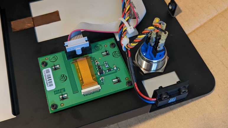
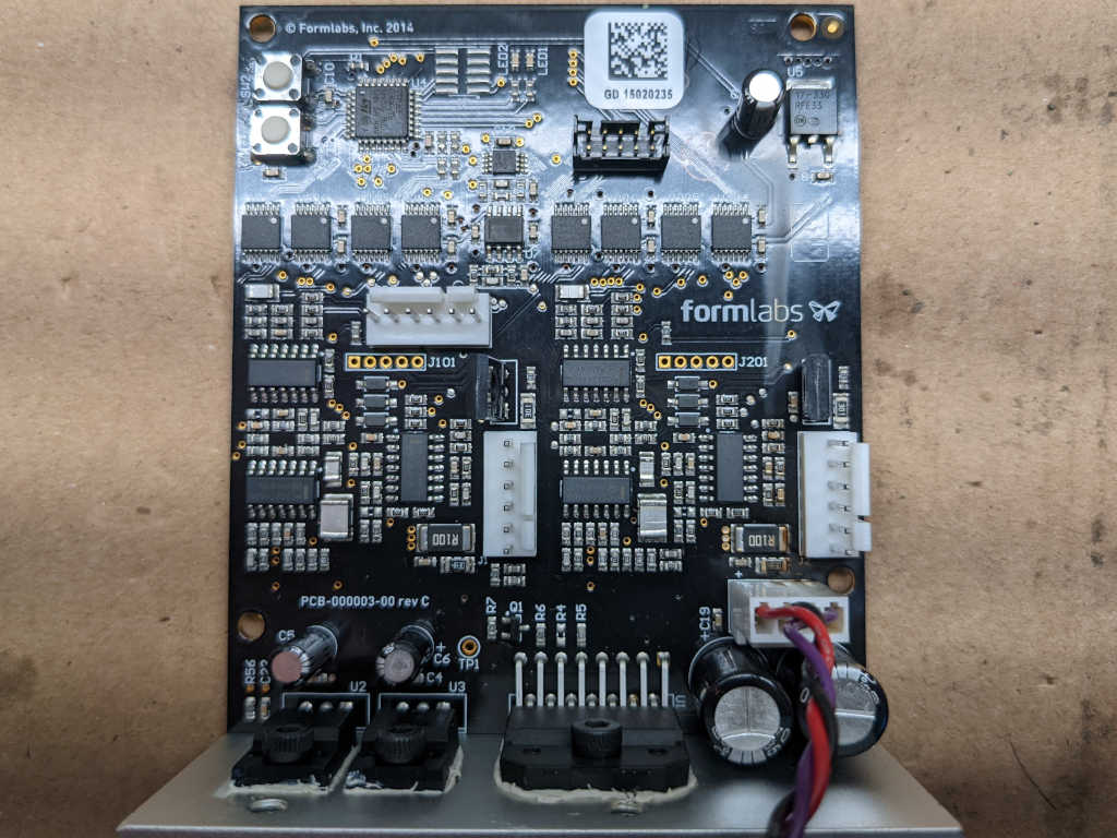
I’m working to understand the OLED dot matrix display from a broken FormLabs Form 1+ laser resin printer. It is hosted on a FormLabs custom circuit board and, after tracing through copper traces of that board, I have a candidate list of five wires for further investigation. When I went to attach my Saleae logic analyzer, I decided to attach probes to all eight unknown wires. (Out of ten wires total and I have identified two: the ground and 3.3VDC Vcc wires.) It wasn’t much extra effort and I was curious if anything was going on. I then captured traces for four activities:
- Power-on: when I plugged the 24VDC power supply into the printer.
- Startup: when I pressed the front panel button to start its logo animation, ending at the “lid is open” warning.
- Steady: Several seconds when the display stays at “lid is open” warning, with no updates.
- Ready/Open/Ready: Using a magnet, I toggled the display from “ready” to “cover open” and back to “ready” again.
Trace for “Steady” showed no activity at all. I had expected the system to refresh the display periodically regardless of update activity, but I just captured five seconds of silence. This is quite a contrast from the super chatty display from an AT&T CL84209 handset where I had 2569 messages within 10 seconds! Here I have nothing. Well, at least that was out of the way.
Trace for “Power-on” and “Startup” was interesting because it captured activity on two of the three wires that were unused. One looked like clock and another looked like data, so I asked Saleae Logic to treat them as I2C. They came back as valid I2C messages.
write to 0x48 ack data: 0x01 0x00
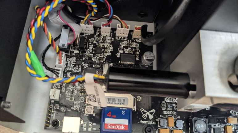
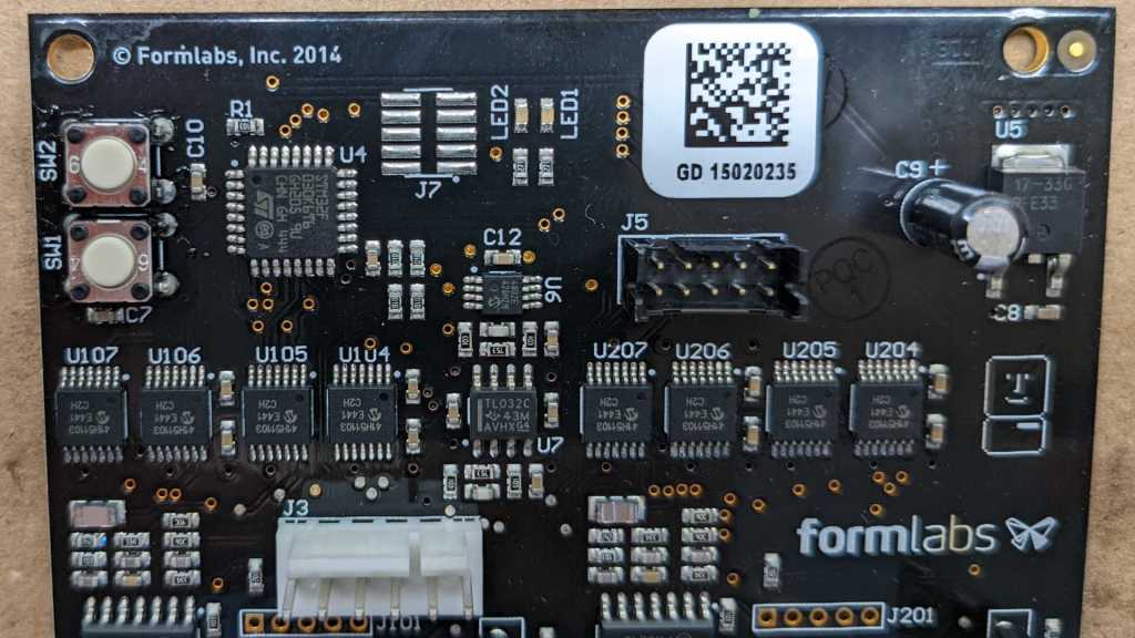
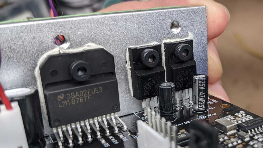
write to 0x48 ack data: 0x00Hypothesis: printer mainboard has an I2C peripheral bus and it’s been routed all the way to the OLED display module circuit board. I2C is not used by this particular display module, but the design gives FormLabs an option to switch to an I2C display module without changing the rest of printer hardware. In the meantime, a logic analyzer connected to the display module would see traffic on the I2C bus. By this hypothesis, such traffic is intended for other components instead of this display, so I’ll ignore it until/unless I discover a reason to revisit. [UPDATE: I found a NXP LM75B on the mainboard, an I2C temperature sensor that could answer to address 0x48.]

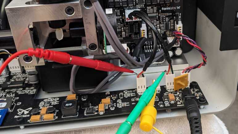
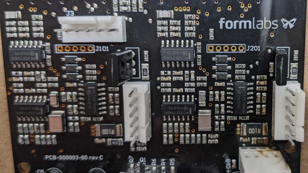
Back to the five wires of interest: three wires showed activity correlating with screen updates. I didn’t see any activity independent of screen update, so these wires might be a dedicated peripheral data line. If it is a peripheral bus, every other peripheral on the bus stayed quiet during my test set of activities. At first glance I thought this was SPI, but a closer look revealed behavior inconsistent with SPI.
- Mainboard cable pin 3 — connected to logic analyzer channel 0 (white line) — showed infrequent level changes near the start of every activity. A good candidate for SPI “Chip Select” or Enable, except data transfers seem to happen both when it is low and when it is high. Which shouldn’t happen if it is indeed Enable.
- Mainboard cable pin 4 — connected to logic analyzer channel 4 (yellow line) — shows regular level changes during every activity. A good candidate for SPI Clock, except the candidate data line changes within each “clock” pulse” which shouldn’t happen if it is indeed clock.
- Mainboard cable pin 6 — connected to logic analyzer channel 5 (green line) — shows level changes at irregular bursts. A good candidate for SPI Data, except it pulses out of sync with “clock”.
If this is SPI, why does it look weird? If this is not SPI, what is it? I’ll have to check over my setup and try again.


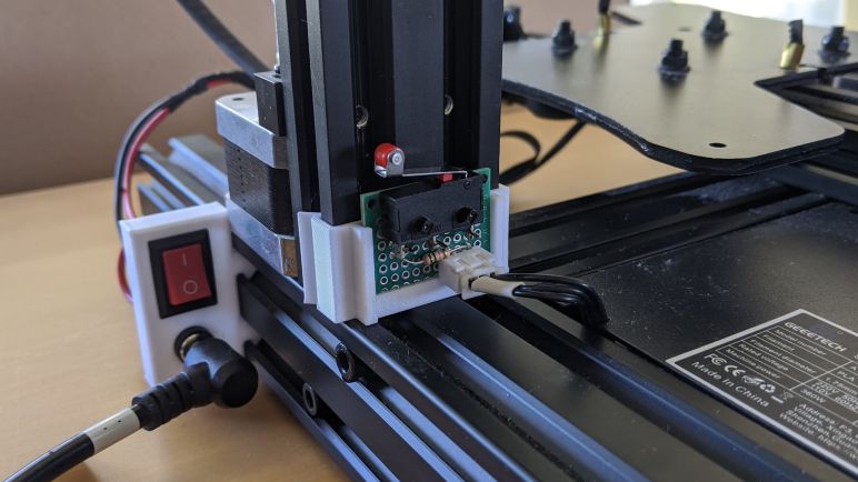

 Once I had a small circuit board to hold the switch wired to the appropriate
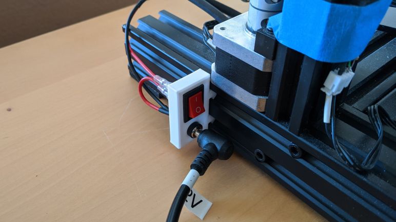
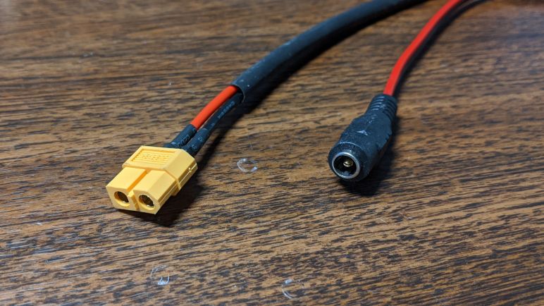
 A reduced top speed was still good enough for me to proceed so I drew up a quick 3D printable power panel for the printer. Since the 12V DC power supply was from my