ESP32 Exercise: Stepper Motor Pulses With LEDC PWM

After successfully installing PlatformIO’s ESP-IDF support (and a sigh of relief nothing else seems broken on my computer) I resumed practicing writing code for ESP32. The next exercise was motivated by Emily’s optical audio decoder project where we traded a few e-mail about generating stepper motor signals. For her project she used an Arduino and the AccelStepper library, but it has a maximum speed of roughly four thousand steps per second on classic Arduinos. I was confident the ESP32 can do far better than that, and decided to try it myself.

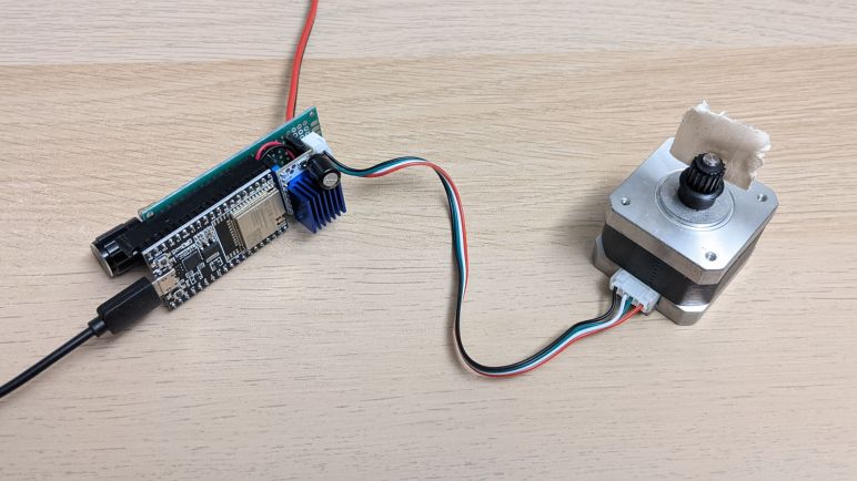
It was also an opportunity to play with a Trinamic TMC2208 breakout board sometimes called the SilentStepStick. I think this board might be a Trinamic original design, but there’s a slight chance they just hosted materials on their website since it was such a popular use of their chip. Either way, there are a lot of Amazon vendors selling these in affordable multi-packs(*) targeting the 3D printer market. Mostly for people who are unhappy with the high-pitched whine of many inexpensive 3D printers, because TMC2208 is a good choice for helping a printer run much silently than they would on the very popular A4988 driver chip that helped start the current wave consumer 3D printers. My own 3D printers had A4988 drivers soldered on the board so I couldn’t use these modules to upgrade, but I foresee these modules becoming useful in other projects.

In the current Sawppy rover context, these drivers may become useful if I investigate using stepper motors in a future rover iteration. I’ve already received requests to drive and steer Sawppy wheels with NEMA17 style stepper motors commonly used in 3D printers, and there’s always that mythical robot arm that my rover is still patiently waiting for. Commodity NEMA17 motors typically have far less torque than LX-16A serial bus servos, but I’m not sure it is a critical difference for a rover and the best way to find out would be to build one.

But for now I’m just looking at the stepper motor driver, which is commanded by two signal pins: one signifying direction, and another that signals a step for the stepper motor. Direction pin is fairly trivial, it’s the step pin that presents a challenge. Generic portable code like AccelStepper couldn’t reliable pulse the step pin at high speeds, that requires coding to the hardware as GRBL did for the ATmega328.

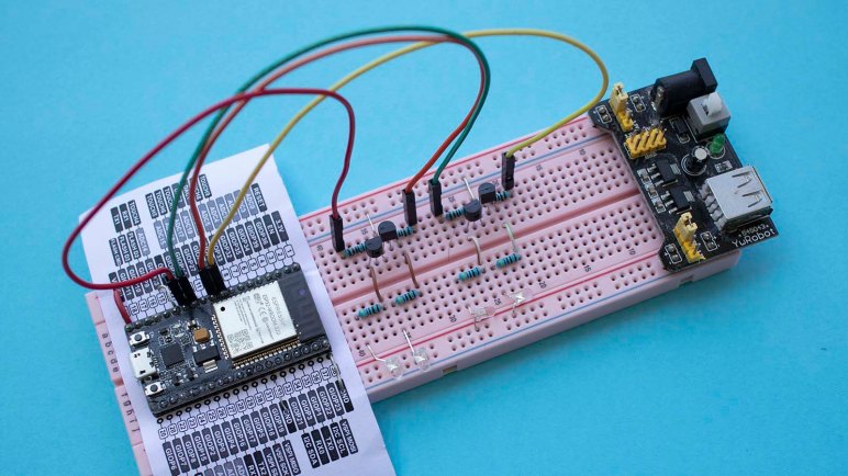
For the ESP32, my experiment used the ADC peripheral to read the position of a potentiometer and the LED control hardware PWM module to generate step pulses. This module is optimized for dynamic adjustment of pulse width duty cycle during application execution, but stepper motor control is a bit of a off-label use where I left the duty cycle at 50% and changed the PWM frequency at runtime in response to knob position.

According to LEDC peripheral documentation, it is theoretically capable of up to 40MHz pulses at 50% duty cycle. However, for any given configuration, the ESP32 is constrained to a subset of the total range of speed possible. I’m not sure how feasible it is to reconfigure the LEDC peripheral at runtime, but such tricks will be required for anyone with ambition to generate a wider range of pulse frequencies. In my exercise it is limited to a range of 32 Hz to 32.5kHz, which is plenty for today as proof we can surpass the 4kHz limit of AccelStepper on a ATmega328. A stepper motor’s torque diminishes as the speed rises, so I expect the stepper motors will run into mechanical problems well before becoming limited by ESP32 PWM frequency range up to 40MHz.

Once I got this exercise up and running, I started eyeing a desirable luxury advertised by PlatformIO: source-level JTAG debugging.

Code and schematic for this practice exercise is publicly available on GitHub.


(*) Disclosure: As an Amazon Associate I earn from qualifying purchases.

Using PlatformIO For ESP-IDF Development

Based on my limited experience, the installation script for ESP-IDF (Espressif IoT Development Framework) made some assumptions about an ESP-IDF developer’s computer, including the all-too-common assumption that nothing else will be on the computer. This is problematic for several reasons, but the one that made me pull back was Python. Python is infamous for its problems keeping track of different version and their associated code libraries. It’s such a common problem there are tools made specifically to help developers keep Python ancillaries organized. I’ve had first experience with venv and conda and I understand there are many others. In the absence of such isolation in the default installation script, I went online looking for others who have taken a stab at keeping ESP-IDF from messing up the rest of my computer.

I found a few blog posts and GitHub repos, but what made me happy was a reminder that I already have experience with one solution to this problem: PlatformIO has support for ESP-IDF development. I encountered PlatformIO earlier in the context of HX711 strain gauges interface with an Arduino Nano, so my computer already had PlatformIO on board configured for Arduino on classic ATmega328. I can switch it to Arduino on ESP32, but right now I’m more interested in PlatformIO’s promise to make ESP-IDF easy to install, isolate, and eventually uninstall.

There are a few downsides to this approach. First is the fact I’m no longer using ESP-IDF directly, and thereby adding the possibility that a problem might be caused by PlatformIO instead of Espressif or myself. I would also have to switch over to PlatformIO project structure which is not the same as the ESP-IDF application template. This had greater repercussion than I initially thought, because it’s not just a matter of where the source files were placed. While those source files are still calling the ESP-IDF API I can read in Espressif documentation, the portions of documentation about project configuration may or may not apply. When working directly in ESP-IDF, a lot of project configuration is done by running idf.py menuconfig and that’s not necessarily the case anymore. The people who work on PlatformIO ESP32 support recently added some sort of compatibility in response to user requests, so that’s something I’ll have to look into later.

I’m willing to accept some limitations in exchange for PlatformIO’s ability to keep ESP-IDF Python separate from anybody else’s Python on my computer. As long as I can figure out how to do what I want to do on an ESP32… which means it’s time for more ESP32 programming exercises!

ESP-IDF Up And Running on Ubuntu

Since I decided to learn to write code for ESP32 using Espressif’s own tool ESP-IDF for the sake of following official instructions, I went straight to the official directions for installing ESP-IDF and saw it was the “run this one script to install everything” type of instruction. This is not itself a problem, but when I saw that ESP-IDF had a lot of Python scripts, that made me suck air through my teeth. Automated scripts doing unknown things to Python (without mentioning any kind of environment isolation like venv or conda) sets off many alarms. Hesitant to run ESP-IDF installation script on my main computer, I tentatively dipped in my toes by using a computer running Ubuntu I could dedicate to this experiment. A long but uneventful installation process enabled me to compile the ESP-IDF project template and I proceeded to do a few introductory projects on this test machine.

After the trivial blinking light exercise, I moved on to the ADC (analog-to-digital converter) peripheral. When I built a wired handheld controller for Sawppy V1 with an Arduino Nano, its joystick position was read using an ADC and I expect I’ll need something similar again for micro Sawppy running on ESP32. The unexpected twist I had to learn was the attenuation parameter for ESP32 ADC input. Most microcontrollers ADC can read the range from zero volts to input voltage level. (For an Arduino Nano, 0V to 5V.) So I expected the ESP32 to read from 0V to 3.3V. But by default it only reads up to a much lower level and, even with maximum configurable attenuation, it only reads from 0V to roughly 2.6V. Meaning the joystick potentiometer’s center point will not map to the middle of the allowable range of values. But I was able to take Espressif’s sample ADC project and simplifying it for my needs. I removed all the parts that dealt with calibration and conversion to an accurate voltage reading. Such efforts are largely wasted on a low-quality joystick anyway, they drift far more than the ESP32 will.

The next exercise was to take that ADC data and do something with it. I expect to use ESP32 MCPWM peripheral to control micro Sawppy’s six rolling wheels, so I started learning how to use the LEDC peripheral to generate control signals for micro Sawppy’s four corner steering servos. When an Arduino ESP32 project implements the servo() command, they usually turn to LEDC and I decided to follow suit. Generating a one-to-two millisecond signal every twenty milliseconds is well within the capabilities of the LEDC peripheral, and at the end I had a simple ESP32 servo tester generating servo control signals based on the position of a potentiometer.

So far so good. Out of all operating systems at my disposal, Ubuntu was the least problematic one and I’m glad it passed the first few tests. But this was a test computer, with nothing else on it to break. Certainly no other critical Python dependencies. In contrast, Apple Mac OS X is infamously temperamental about its integrated Python and woe to anyone who messes with it.

Windows lies somewhere in between, with no hard system dependencies to fatally break, but still a complicated relationship with Python. Still wary, I whipped up a Windows test computer and ran the ESP-IDF installer. According to ESP-IDF Windows setup page, it was supposed to install associated dependencies including Python 3.7. But when I launched idf.py I got a Python 2.7 error.

error while loading shared libraries: libpython2.7.so.1.0: cannot open shared object file: No such file or directory

Ugh, what a mess. Now I’m very glad I had used test computers for these experiments. I shall proceed to wipe them clean and consider alternate options.

[Practice projects described in this post are publicly available on GitHub]

Evaluating My Options for ESP32 Development

Once I decided I could use ESP32 as a micro Sawppy rover brain, the next decision is how I intend to write my code to run on an ESP32. Since it’s such a popular microcontroller, I have many options that I’ve narrowed down to top three candidates: ESP-IDF, Arduino, and MicroPython.

The lowest level option is ESP-IDF: Espressif IoT Development Framework. This is the software development kit released by the same people who made the ESP32 hardware. All sample code in Espressif documentation will be targeted to ESP-IDF, so this is the best option if I’m working from the official reference sources. This is important when working with less-popular features like the MCPWM module designed for motor control: I can be confident the feature will be supported.

The mid-level option is Arduino adapted for the ESP32 hardware. Setting up the Arduino IDE for ESP32 development is a very simple process compared to the setup procedures for ESP-IDF. It also allows access to the huge catalog of Arduino libraries that exist out there. Or at least the subset that don’t have hardware dependencies. Code that is hard-coded for ATmega328P won’t run on an ESP32, but that problem is shared with other non-AVR Arduino compatibles like Teensy or even the newer Arduino boards. Architecturally this is a translation layer on top of ESP-IDF, so non-ATmega328P features like MCPWM can be accessible as long as the proper header declarations are in place. Which, in the case of MCPWM, they appear to be.

The high-level option is MicroPython for ESP32. Where the user doesn’t even really need to install anything on their computer: anything that can open a serial terminal will do. The Python language itself is much more beginner friendly than the C language used by Arduino and ESP-IDF. However, a search for MCPWM support found that it is currently a work-in-progress, eliminating it from consideration for this project.

With that elimination my choices are between using ESP-IDF directly versus the Arduino translation layer, I favor direct usage because I saw it as eliminating a variable. When my code doesn’t work, I won’t have to wonder if it’s a bug in my code or in ESP32 Arduino core. While not a huge concern in the well-trodden paths, it is a worry when I venture to less popular sections like MCPWM. And since I’m using an ESP32-specific peripheral, this code won’t run on any other Arduino-compatible boards anyway. Might as well go straight to the source.

Micro Rover ESP32 Brain Is Feasible

I was a little disappointed when I learned that the ESP32 can only use a tiny fraction of its vast peripheral interface capabilities due to the fact there are only a few physical I/O pins to be allocated among them. But to be honest, roughly 20 is a fair number in terms of controllers in this price range. It’s only “few” when compared to literally hundreds of possible uses for those pins. It also makes sense when we think about the target market for the ESP32: it was derived from the ESP8266, and they are both intended to act as a WiFi interface to some device, not to be in charge of a large complex thing. So does my little rover qualify as a small focused-purpose device that needs a WiFi interface? I think so, but it’s a tight fit.

I originally intended to drive L298N by digitally setting the direction on its two input pins and put a PWM signal on the enable pin to control velocity. The straightforward implementation of this would require 3 pins per wheel. Six wheels mean 18 pins, and I still need four more. One for each of the four corner steering servos. I don’t think I can get 22 output pins on the ESP32 dev board I have. Fortunately it isn’t quite that bad, because all three wheels on one side of the rover are always rotating in the same direction, so they can share the same direction control pins. Two pins to control all left wheels, two more to control all right wheels, and one pin for each of the six wheels for PWM add up to ten pins, plus four more for corner steering servos add up to fourteen pins. This will work.

Alternatively, I can implement the control scheme used by Espressif’s sample program for controlling a L298N motor controller using ESP32 MCPWM peripheral. I’m skeptical of this one, though. It wants the enable pin to be tied high, and controls speed by using PWM signal on the direction pins. As per my understanding of L298 data sheet, this toggles between powered state and brake state. Which sounds like an extremely inefficient way to control velocity. Nevertheless, doing this would require 2 PWM pins for each of the six wheels. Plus the four corner steering pins for sixteen output pins. Even though there are only fifteen easy to use output pins, I can probably make one of the caveat-encumbered pins work for the sixteenth.

The final consideration: what would happen if I decide I don’t want to use the L298, and want to use a different motor controller instead? I haven’t studied them as much as I’ve studied the L298, but the few I’ve glanced at appear to use one of the two above control schemes. Perhaps the L298 is established enough that most newer DC motor controller offer drop-in compatibility with L298 control signals? Even if not, I believe a mini rover using another DC motor controller would still be feasible to implement on an ESP32. And the best way to know for sure is to start writing some code.

Notes on ESP32 Input Output Pins

As I combed through ESP32 documentation for information on its PWM capabilities, I realized there was something missing from what I expected to see: information on which physical pins are associated with these PWM peripherals. This was something I saw and learned to expect from reading documentation for other microcontrollers like the PIC16F18345. When I read about a peripheral, it is always accompanied by a chart showing which physical pins are wired to that peripheral. But not the ESP32.

The reason became obvious as I started browsing ESP32 peripherals, a list that just kept going on and on and on. There are so many features on this chip for doing so many different things, how can we possibly use them all? Well, sadly, we can’t. Only a small fraction of this chip’s internal capabilities can be routed to the limited number of external pins. So this chip can do many interesting things, but it can’t do them all at the same time.

The key documentation here is the ESP32 Technical Reference Manual. (PDF) Section 5 talks about the GPIO matrix, which is what we configure when we write an ESP32 application using GPIO peripherals. According to this document, all the ESP32 peripheral inputs added up to 162 potential signals, and all the outputs added up to 176 output signals. The GPIO matrix is how we control which of those 338 (!!) pins are routed to the 34 physical pins actually available on an ESP32. I found it amazing that, by definition, we could only use ~10% of an ESP32’s input/output capabilities.

And in reality, we are even more constrained than that. Especially when working with a ESP32 DevKit module as I am. The physical appearance of 38 pins are a little misleading, because there are multiple ground pins (all tied together, at least on my board) and both input and output voltage of the onboard 3.3V regulator. Six pins are tied to onboard flash memory and thus not available for use, and given the fact they are unusable I’m puzzled why they even broke them out on the dev kit. The UART for uploading programs are also exposed, meaning a few more pins unavailable for projects. Then there are pins involved in the boot and firmware upload process, and those involved in JTAG debugging.

I found it all very confusing, but thankfully I found an ESP32 GPIO reference chart by Random Nerd Tutorials which I consider a great resource for navigating this particular jungle. According to this chart, there are only 15 GPIO pins that an be used without caveats. Four more are limited to input-only and lack internal pull-up or pull-down resistors. Roughly 4-6 more pins are available depending on my appetite for adventure and confidence, followed by their associated restrictions. The rest might as well have been marked “HERE BE DRAGONS” and I’m staying away from them for my micro Sawppy brain project.

Notes on ESP32 PWM Peripherals

Now that we’ve celebrated the success of Perseverance rover’s arrival on Mars, I resume working on my little rovers. I was happy to discover that I’m less intimidated by the ESP32 than I was over two years ago. I now have a basic understanding of its capabilities and the ecosystem that has grown up around it. Enough to figure out where to start if I have a problem to solve. And the problem of the day is to determine if micro Sawppy can use an ESP32 as its brain.

The reason I started looking at the ESP32 is because of its WiFi capability and its low cost. I liked the idea of web browser-based UI like what I wrote for SGVHAK rover and adapted for Sawppy. But that ran on a Raspberry Pi which, even in its lowest-cost Pi Zero form, is far more expensive than an ESP32. My experience with other ESP32 projects like Ben Hencke’s Pixelblaze and Bart Dring’s Grbl port taught me the ESP32 is quite capable of serving up HTML user interfaces. So the next thing to do is to verify an ESP32 can generate all the control signals for a Sawppy rover, which means investigating its PWM capabilities.

PWM (Pulse Width Modulation) is a tool that can be used to solve many problems in a microcontroller. For micro Sawppy I need PWM capability to control four steering micro servos and the six wheel drive motors. It doesn’t matter if they are micro servos modified for continuous rotation or a real DC motor driver like the L298N, they all need PWM signals. And what I found was that no only can ESP32 generate PWM signals, it has separate interfaces dedicated to specific problem someone might want to solve with PWM.

First up is LEDC, the Light Emitting Diode Control module. I bring this up first because our first project with any new piece of electronics is to blink a LED, and in many tutorials the next step is learning how to vary the brightness of a LED via PWM. LEDC is designed with the intent of controlling intensity of up to 16 LEDs via PWM.

Another problem commonly solved with PWM is to convert a digital signal into an analog one. This is sort of like controlling the brightness level of a LED, but some applications are sensitive to the sharp pulse transitions of a PWM signal. One example is for generating sounds, which needs a smoother output. And here the ESP32 delivers a dedicated DAC (digital-analog converter) peripheral. Anticipating that this would be used for audio, Espressif provisioned it to interface with I2S which is popular with audio applications. This may be fun to look at later, but it is not critical for driving a little rover.

And finally, I was surprised to find there is a dedicated Motor Control PWM module for generating PWM signals sent to motor driver modules like the L298N. It included many motor-specific features absent from LEDC, but they are mostly aimed at controlling brushless motors which usually have three coils each requiring independent control. ESP32’s MCPWM is set up to control two brushless motors, which means controlling six coils. But it is not required to control brushless motors, each of those coil control an be used to control a single DC brushed motor.

So the ESP32 MCPWM peripherals can control six brushed DC motors, which is a perfect fit for a six-wheel-drive little rover. I should be able to use four channels of LEDC to generate PWM to control four steering servos. This first pass over the spec sheet supports the idea of using ESP32 as little rover brain, though there is a potential problem in assigning control signals.

ESP32 Feels Less Disorienting This Time

Seeing all the interesting projects built with an ESP32 has made me interested in learning more about the popular platform, but it wouldn’t be real until I dedicate the time and focus to build some projects of my own. My micro Sawppy project might be the motivation I needed to get down to business.

Querying in this blog’s history, I was embarrassed to realize that it’s been over two years since I first thought I would build something with an ESP32. My first exposure to the fire hose of information online was overwhelming. But I returned occasionally to pick off little bite-sized pieces to digest. Reading documentation on some specific aspect on the ESP32 at a time, usually in response to seeing someone’s project making cool use of that particular aspect. I wanted to see how it was done!

During this incremental learning, I picked up on the fact something is coordinating the works to keep all the plates up in the air. Eventually learning that the default ESP32 runtime environment includes a minimalist operating system for embedded hardware: FreeRTOS. Which was a world onto itself! There is a tutorial e-Book to help get people up to speed but again, it is a lot of information that I had to digest a little bit at a time. I’ll write more about FreeRTOS later.

And though I hadn’t reached the point of writing my own ESP32 code, I did start getting a bit of hands-on experience working with an ESP32 developer board. Which was more full featured than the minimalist mesh networking Supercon hack that was my first introduction to the hardware. Even though I was only running other people’s code (like Bart Dring’s ESP32 Grbl port) and not my own code, it was valuable familiarization of the ESP32 landscape.

All of these individual pieces built up a comfort level that was absent from my first time facing the avalanche of information available for ESP32 over two years ago. Now I can look at the page like ESP32.net and have a much better understanding why things are organized the way they were, and which pieces of information are relevant to others. This knowledge map is important as I do some basic due diligence to see if it’s feasible to build a micro Sawppy brain from an ESP32. Before I get any further on my little rovers, though, there’s a big event for a big rover.

Thoughts on Micro Sawppy Brain

My diversion to learn a bit of Unity 3D was a good change of pace, but now I will set that aside and return to rover work. My latest little rover Micro Sawppy Beta 3 (MSB3) had a few interesting features that I reviewed before taking this Unity break, most recently a few notes on MSB3’s living hinge differential link. MSB3 was built around the TT gearbox, which requires DC motor drivers commanded by some kind of rover brain.

I have the option of using the same brain I used for MSB1 and MSB2, which was adapted from Sawppy V1 and allowed me to control everything with servo PWM control signals. This worked for MSB1 and MSB2 because they were all micro servos. Four in their original form for steering, and six modified to continuous rotation to drive the wheels. But now that I’ve converted rover locomotion to DC gear motors, I’ll have to switch to something else.

My current generation of rover software was originally written for SGVHAK rover, which had DC motors in its wheels and used RoboClaw motor controllers. Those are nice, but far too expensive for my micro Sawppy price target. Or I could continue controlling via PWM by using forward/reverse brushed DC motor controllers(*) from the world of remote control hobbies. These are far less expensive than RoboClaw controllers but also less capable. Unfortunately they are still too expensive to meet my price target. Motivation to find a cheap commodity was why I investigated commodity L298N driver boards earlier.

But I’ve always known I couldn’t keep using a Raspberry Pi. In order to meet my price target, I have to swap it out for something more affordable. For MSB1 I chose to use the Pi as a known quantity, because the rest of the rover was all new and I wanted to reduce the number of unknowns for the first prototype. After several revisions I’m at MSB3 and I’ve decided it’s fine if a baseline micro Sawppy didn’t have the computing power of a Raspberry Pi as long as there are provisions for people to upgrade if they wish. So any microcontroller capable of generating the required PWM control signals (for servos and for L298N motor drivers) would suffice. The classic Arduino is always the first candidate I consider for a project, but ATmega328P based Arduinos only have 6 PWM channels. That’s not enough here so I have to move upscale.

Classic ATmega328P-based Arduino are also missing another very important feature: WiFi. SGVHAK rover’s Raspberry Pi based brain served up a web browser-based rover control interface. Controlling Sawppy from my touchscreen phone was very useful. Not just because of convenience but also because I didn’t need to worry about building a separate device to act as handheld controller. Which, in a bit of cheat, also meant I did not counted the cost of controller phone in micro Sawppy budget. I justified this by saying many people today have old web-capable touchscreen phone or two sitting around collecting dust. Maybe a stretch, but I’m going with it!

If I want something more powerful than a classic ATmega328P-based Arduino, but more affordable than a Raspberry Pi, and can handle web-based network traffic over WiFi, the top candidate is pretty obvious: ESP32, we meet again.


(*) Disclosure: As an Amazon Associate I earn from qualifying purchases.

Examining Composite Video Signal Generated By Microcontrollers

There was a several-years-long period of my life when I spent money to build a home theater. This was sometime after DVD became popular, because the motivation was my realization of how much superior DVD picture quality was over VHS. With movies on VHS, noisy visual artifacts were a limitation of the analog magnetic medium. With movies on DVD, the media-imposed limitations were gone and now there are all these other limitations I could remove by spending money, lots of it, to do things like upgrade from composite video to S-Video connections.

Eventually home theater moved to all digital HDMI, and I stopped spending big money because even the cheapest flat panels could completely eliminate classic CRT problems like color convergence. (My personal peeve.) I thought I have left the era of CRT and composite video behind, but throwing out my pile of analog interconnects and video equipment turned out to be premature.

Now I’ve found an interest in old school video again, because they are accessible for the electronics hobbyist. It is much easier to build something to output a composite video signal rather than HDMI. Local fellow maker and tinkerer Emily likes the old school tech for aesthetics reasons in addition to accessibility. So one day we got together at one of our regular SGVTech meets to dig a little deeper into this world.

Emily brought an old portable TV with composite video input, and two candidate Arduino sketches each purporting to generate composite video. (arduino-tvout and one other whose name I can’t remember now.) I brought my ESP32 dev module running Bitluni’s composite video demo. For reference Emily had an actual composite video camera, the composite video Wikipedia page and the reference document used by Bitluni for his demo.

All three were able to get the little TV to show a picture. However, they looked very different under the oscilloscope. The [name will be filled in once I remember] sketch had the wildest waveform whose oscilloscope trace didn’t look anything like a composite video signal, but the proof is in the fact an animated 3D vector graphic cube showed up on the TV anyway. The waveform generated by arduino-tvout was a little rougher than expected, but unlike the previous, it was clearly recognizable as a composite video waveform on the oscilloscope and accepted by the TV. Waveform generated by Bitluni is the best fit with we expected to see, and matched most closely with output generated by the composite video camera.

Knowledge from tonight’s investigation will inform several of our project candidates.


ESP32 Grbl Controller Breadboard Prototype

An ESP32 plus Grbl motion control software seems like a good candidate for running an old industrial XY table, definitely promising enough to move forward with prototyping. I had originally intended to use an Olimex ESP32 DevKitC (*) as it was equipped with two rows of sockets. This is easy to connect with jumper wires while not leave pins exposed to risk of short circuits.

This plan was short lived, because I quickly ran into a problem: The ATmega at the heart of an Arduino is a beefy 5V part that can supply up to 40 mA per pin. In contrast, the ESP32 is rather delicate 3.3V part that should not exceed 12 mA per pin. The data sheet for the ZETA4 controller I want to connect to this board expects a minimum of 3.5V to signal step and direction, which means I need external components to shift the ESP32 voltage level up to what the ZETA4 expects. When I made this discovery I was momentarily tempted to switch back to an ATmega solution, but the siren call of higher performance carried me forward.

Since I would need external components, the project brain switched to my HiLetgo ESP32 development board (*) which is mostly identical but came equipped with two rows of pins appropriate for a breadboard. Four level-shifting units were installed, each built around a 2N2222A transistor. They were connected to the step and direction pins for X and Y axis, and each received a LED (and corresponding current-limiting resistor) to indicate activity.

Staying consistent with the system I used for Glow Flow, red LEDs indicate X axis activity and green LEDs indicate Y. These LEDs allowed me to perform a quick test to verify the presence of blinking activity. Next step: connected them to ZETA4 controller to see if the motors move as commanded.


(*) Disclosure: As an Amazon Associate I earn from qualifying purchases.

Evaluate Grbl For XY Stage

I considered driving an old industrial XY table from a 3D printer controller board. I have a Melzi board on hand to use but its onboard stepper drivers were too well integrated to be easily adapted to this project. I considered running Marlin on an Arduino directly, but if I’m going to start building my own control board instead of one already tailored for Marlin, it makes sense to look at other options. Given the popularity of the Arduino platform, there’s more than one motion control project out there for me to consider.

Enter Grbl.

Unlike Marlin, which is primarily focused on 3D printing, Grbl offers a more generalized motion control platform. Provisions already in the code include pen plotting, laser cutting, and 3-axis CNC milling. All of which could be done with Marlin as well, but with different amount of code modifications necessary.

But an even bigger advantage in favor of Grbl is the existence of an ESP32 port. Marlin’s development team is working on a 32-bit hardware abstraction layer (HAL) to take it beyond ATmega chips. It looks like they’re up and running ARM Cortex boards and have ambition to bring it to ESP32. But a Grbl ESP32 port is available today and stable enough for people to use in their projects.

The headline feature is, of course, speed. While AccelStepper topped out around 4 kHz pulses, Grbl on ATmega is good for approximately 30 kHz. Grbl on ESP32 claims “at least 4x the step rates” which is likely a very conservative claim. After all, we’re comparing an 8 MHz 8-bit chip to a 240 MHz 32-bit chip. Though running on the ESP32 does incur more overhead than bare-metal code running on an ATmega, which is important in time-sensitive applications like motion control.

There are upsides for this real time operating system (FreeRTOS) overhead, as it allows the ESP32 to handle things beyond motion control. The best part employs its WiFi module to present a web-based control interface. A control interface would have required additional hardware in a Grbl machine built around an ATmega, but with Grbl on ESP32 I just need a web browser to start testing.

And since I already have an ESP32 development board (*) on hand, this looks like a great venue to explore. Let’s try running this XY stage with an ESP32 running Grbl.


(*) Disclosure: As an Amazon Associate I earn from qualifying purchases.

Entering the Wide World Of ESP32

Espressif Logo

As a thanks for participating in the ESP32 mesh network project by Morgan and Ben, people whose badges became nodes on the network were generously gifted the ESP32 module mounted to each of our badges. Unfortunately, I managed to damage mine before the big stage demo so sadly I didn’t put in the honest work to earn that ESP32. Still, I now have a damaged ESP32 that I can try to fix.

Before I start trying to fix it, though, I should have a better idea on how to tell if a ESP32 is up and running. The only mechanism I had before was to run the badge mesh network app and see if there’s any response, but I want to know more about how a ESP32 works in order to better tell what’s broken from what’s working. Also – since I’ve desoldered my ESP32 from the carrier board, it is not nearly as easy to test it against the badge.

I’ve read about a lot of projects built using the ESP32 on Hackaday, so I know it’s popular for and it would be cool to add it to my own project toolbox. Given its popularity, I thought it wouldn’t be a problem to find resource on the internet to get started.

I was right, and wrong. There is no shortage of information on the internet, the problem is that there’s too much information. A beginner like myself gets easily disoriented with the fire hose of data presented by ESP32.net.

Do I start with Espressif’s own “ESP-IDF” development framework?

Do I start with an Arduino-based approach to ESP32 development?

Do I start with Amazon’s tutorial for how to use an ESP32 with AWS?

How about other individual tinkerer’s adventures on their own blogs? Here’s one person’s initial report poking around an ESP32, including using an oscilloscope to see how quickly it can change output based on input. And here’s another Hello World, and there are many more blogs covering ESP32. (Soon including this one, I suspect.)

It’s going to take a while for me to get oriented, but it should be fun.

Miss At Supercon: ESP32 Mesh Network Demo

In the pre-Superconference badge hacking call to action, wireless badge communication was raised as a specific challenge laid out for attendees to tackle. One particularly ambitious effort was to build a mesh network for wireless communication using ESP32 modules mounted to the badge expansion header. The ESP32 mounting system is straightforward, it was the software that would prove to be tricky.

At the end of the weekend, Morgan and Ben got the network up and running with just over an hour to spare. They started recruiting people to join their IRC-style chat network for the final demo, and I signed up. In the test session I was able to see messages sent over the network, and send a few myself. But when it came time for the actual demo on stage, my badge was unable to connect! Fortunately they had enough other participants so my participation was not critical, but I was sad to have missed out. After the presentation (and winning a prize) the team told everyone on the network we could keep the ESP32 as a token of thanks.

After the conference I examined my ESP32 mount and found a few cracked solder joints. It looks like I had accidentally smashed my ESP32 module sometime between the test session and the presentation. Looking on the Hackaday.io project page, I found the simple schematic and tested connections using my multimeter. Several connections were indeed severed between the badge header and the mounting circuit board. I tried the easy thing first by reheating all the solder to see if they could bridge the gaps. This helped, but two lines remain faulty and were patched with wires.

After this patch, I tested with [mle_makes] ESP32-equipped badge and we could not communicate, indicating further problems with my ESP32. The next step is to desolder it from the board to see if I could use the ESP32 as a standalone module. Once the module was removed from the carrier board, I saw a problem: three of the pads had separated from the module, one of them being the EN(able) pin critical to a healthy ESP32. The other two damaged pads (IO34 and IO35) I hope I could live without.

Is this the end of the road for my gifted ESP32? I thought it was, but [mle_makes] disagrees. The next experiment is to try soldering to the trace leading to EN pad, or the via further inboard. This will be a significant challenge – that via is smaller than the tip of my soldering iron!