Solar Lawn Light NiMH Battery Replacement

Years ago I bought an 8-pack of solar lawn lights. They were fun for lighting up the back yard for a few hours after sunset, and I was curious how long they’d last. The answer was about five years, plus or minus a few years, depending on your standards because they gradually fade out. Both in terms of shorter duration after sunset, and in terms of dimmer illumination.

Now only one of the original eight offer any visible illumination, for less than half an hour after sunset. This behavior implies whatever internal energy storage device has degraded over years, and I wanted to take a look to see if I can confirm my hypothesis.

Solar lawn lights are very inexpensive now, and it’s much easier to just buy a new set. The reason I wanted to try reviving these lights is because their center clear section is glass, not clear plastic as many current products use.

Glass won’t yellow and fail after years of southern California sunshine, which is not something I can say for whatever non-glass material was used for the solar cell’s top layer. The paint is also very visibly damaged by sunlight. I can repaint if I want to, but condition of that solar cell looks bad.

Flipping the lid over, I was surprised to see a battery compartment door. I had expected a “no user serviceable parts inside” arrangement. I opened the door and the molded plastic latch broke, brittle from years of baking under the sun.

Inside the door is a AAA NiMH battery cell, literally roasted by the sun while it lived inside a black enclosed compartment. After removing the battery, I took a multimeter and measured the open-circuit battery compartment terminals under sunlight. My meter read 2.095 volts. Yikes! That’s a lot higher than the 1.25V nominal level for a NiMH battery cell. Are NiMH batteries expected to take this kind of abuse? I know NiMH batteries can handle over-voltage better than lithium chemistry batteries, but I didn’t know to what degree. While excess energy can be dissipated as heat, it’s hard to shed energy as heat when it is already very hot from sun. Between the high voltage and high temperature, these cells lived a harsh life.

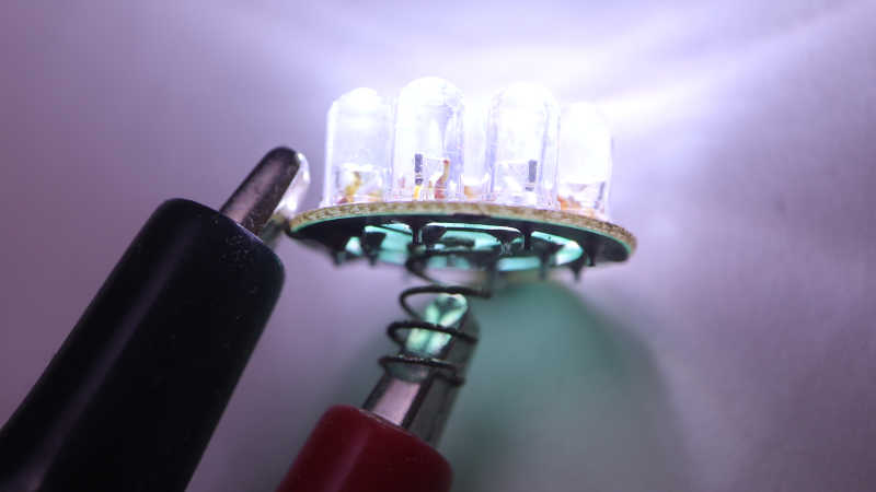
Looking in my pile of NiMH batteries, I found two AAA-sized units and installed one of them. The LED lit up when I covered the solar panel to simulate night, so I decided the old battery must be completely dead. To my surprise, it wasn’t! When I connected it to my “Joule Thief“, the LED lit up and stayed illuminated for days. The battery isn’t completely dead, but not well enough to run this solar lawn light. Connecting it to my bench power supply, I find the LED turns off when battery voltage drops below about 0.9V. In comparison, my Joule Thief will run all the way down to about 0.4V, which is much more demanding on the battery and a bad idea for longevity.

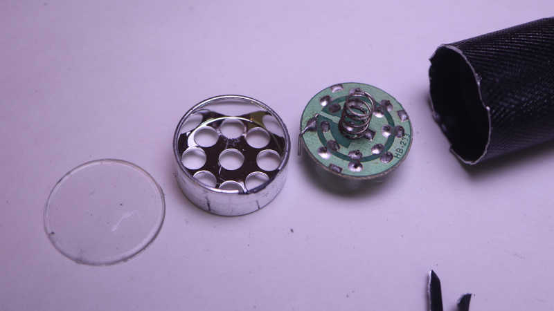
I don’t have many NiMH AAA batteries on hand. I could buy some more, but I don’t particularly relish the thought of buying new batteries just to sentence them to a quick and hot death. I decided to open up the light to see inside. There wasn’t much: the solar panel is well-sealed by a blob of dark gray epoxy, and there’s only a tiny circuit board inside.

The back of the circuit board shows all the signs of something left out in the elements.

As does the front, which showed a YX805 chip in charge of the operation. An online search found a Simplified Chinese datasheet which explained it was specifically designed to run solar lawn lights. Machine translation claimed battery over-discharge protection as a feature, explaining the deactivation at 0.9V. There’s also mention of adjustable battery charge rate, but nothing about over-voltage protection. Either the machine translation missed it, or the designers decided it was OK for a 1.25V nominal voltage NiMH battery cell to face 2.095V charging input. Or perhaps the 2.095V I measured was just an artifact of an open circuit that fails to trigger the battery charge rate limiter?

Given its corroded condition implying it may fail elsewhere in short order, I’m not eager to spend money on new batteries. I have plenty of NiMH cells on hand, though, just not in AAA size. The biggest of which are from Neato battery packs. They’re too old and tired to run a robot vacuum, but perhaps they can run a solar lawn light. I cut the spot-welded tabs in half and soldered to the half-tabs, sparing battery cells from heat of my soldering iron.

Sadly many of those old cells were too weak to get up over that 0.9V minimum bar, but a few of them were good enough to run a solar lawn light (though dimly) for a bit after sunset. Perhaps my solar lawn lights will be my way of giving some old NiMH battery cells yet another life, even if a hot and short one. Or I can use it as motivation to explore another technology: supercapacitors.

Canon PowerShot SD1100 IS: (Mostly) Reassembled Until Next Time

I tried and failed to fix a broken gear I found deep inside my old broken point-and-shoot digital camera. I tried to take it apart non-destructively because there was a small chance I could fix it. Unlikely, given the tiny mechanisms within, but there was a chance. I thought it was more likely that I would find a fault that I couldn’t fix, or that I couldn’t find anything at all, at which point I would proceed to completely disassemble it for the sake of curiosity.

But now that I have tried and failed to fix the fault, I found myself unwilling to move on to destructive disassembly. I didn’t feel it was a “well, that’s that” situation. This feels just barely beyond my reach, and I should be able to think of something in the near future. I’m not ready to give up yet!

This leaves me in an awkward state: I don’t have any more repair ideas to try right now, and I have a lot of scattered camera pieces in front of me. Their current positions on my workbench are a direct reflection of how those pieces fit into each other. If I sweep them into a bag, I will not be able to put this thing back together. With that in mind, I decided to reassemble the camera so I could clear my workbench for other projects until I return to this thing with a new idea.

Manually turning gears tiny bit by bit, I retracted the lens mechanism before putting it back together. Then I electrically connected the assembly to the rest of the camera in a test run configuration:

Typically the lens assembly is in the middle, blocked in by the flash module and other pieces. I don’t want to assemble/reassemble all adjacent pieces every time I want to test something, so I came up with this arrangement. It allows every electronic connector to be plugged in to their right places, but leaves the lens assembly dangling out front so I could easily unplug it. This configuration is a lot more awkward than doing the same thing with an inkjet printer, because every cable is short and have very little slack.

A rear view of this awkward arrangement. This could be a lot neater if there wasn’t a tiny cable connecting LCD to flash module in addition to the wide LCD cable at the bottom. But this is the view I have for verifying I still get “Lens error, restart camera” on screen. While I haven’t fixed the camera, the good news is I haven’t catastrophically damaged anything else either. The bad news is that my laboriously hand-retracted lens was deployed again during startup. Gah! Given the effort it took to manually retract, and the risk I’ll break something if I were to go back in and do it again while frustrated, I decided to just leave the lens extended and resolved to be careful putting this away.

An hour later, I have the camera mostly back together. There were a few pieces of double-sided tape that didn’t hold as it used to, and there were two plastic clips I inadvertently broke when I pulled the lens assembly apart. At the end, I found myself with one extra screw left over despite my notes, pictures, and physical reminder via workbench layout. I don’t remember where this one screw was supposed to go, and couldn’t find a likely place for a missing fastener. Ending with a single extra screw isn’t terrible for a beginner but it shows I have a long way to go before I can be trusted for actual camera repairs!

Canon PowerShot SD1100 IS: Broken Gear

I have a broken point-and-shoot digital camera of circa-2008 vintage, and I think I’ve found the point of failure: a small red gear who is supposed to turn a lead screw but has cracked open.

Without its friction fit grip on the shaft, it now just spins loosely. An optical limit switch told the computer the actuator is no longer actuating, thus the error message on screen. And the crack affected tooth spacing, which means it would no longer smoothly mesh with an adjacent white gear, and thus explaining the mechanical noise.

The crack propagated through the weakest part of this gear, where a hole has been cut out of almost half of its depth. Why is this hole here? It looks too neat and deliberate to be an air bubble in the casting/molding process, and looks too deep to be any manufacturing process artifact I know about. (Injection molding ejector pin mark, injection sprue cutoff, etc.) I’m curious to its intended purpose, which I’m sure is not weakening the gear to fail under stress. But it is broken now, how might I fix it?

Cyanoacrylate Glue

First attempt was to glue it back together with cyanoacrylate. (CA, “Super Glue”, “Crazy Glue”, etc.) A set of calipers acted as small-scale vise to pinch the gear back together, and a dab of CA was dripped into the mystery hole of weakening. A tiny bit was applied to the back side of the crack as well.

After waiting 15 minutes to let the glue cure, I pushed this gear back on the lead screw.

It popped back open, and the cured blob of CA also popped free. I don’t know what the plastic was used to make this little red gear, but the material is apparently not eager to bind to CA glue.

Melting Plastic

If chemical binding doesn’t work, how about some mechanical binding? I thought I would install the finest tip I have for my soldering iron, and melt the plastic across this crack to weld the gear back together.

Of course, “fine” is a relative term. A 0.5mm soldering tip is pretty fine by normal standards, but in this context it is 1/6 of the diameter across this gear, turning it into a blunt heat applicator.

But I tried my best, mostly successfully avoided ruining the gear mesh surface or inner shaft mating surface. Then I repeated the process for the back side of the gear. After it had cooled, I pushed it back on the shaft.

That didn’t work, either, as the gear opened back up again.

I opened this camera up with low expectation of repair. I thought it was more likely that I would find the point of failure, satisfied with “yep, there it is”, and continue taking this apart into its individual pieces. Now that I have this tiny broken gear in front of me, a repair is tantalizing close and I’m not ready to give up yet. However, leaving the camera and all its components scattered on my workbench would keep me from switching to another project, and many of these components are one big sneeze away from disappearing into nooks and crannies never to be found again. To keep all parts together while I think of things to try, I will reassemble this camera before putting it away.

Canon PowerShot SD1100 IS: Sensor Lens Actuator

I have an old broken Canon PowerShot SD1100 IS compact point-and-shoot digital camera, and I’m trying to see if I can find where it broke. My first candidate didn’t pan out so I went looking around inside the lens assembly to find my second candidate: an actuator moving a lens element.

From right to left in this picture, the members of this cast: a stepper motor only a few millimeters in diameter turns electricity into mechanical motion. A lead screw translating rotational motion into linear motion moving the element up-down. A round metal bar acting as the linear rail for this actuator guiding its path. And finally, a spring that compensates for backlash by pulling the lens nut against one side of the lead screw thread.

Near the left edge of this picture, blurry out of focus at around 8 o’clock, is a bit of yellow FPC (flexible printed circuit) attached to a small optical interrupter sensor. A small plastic tab on the lens element blocks the beam, so the sensor can act as a homing switch for this lens actuator. It would also explain how the camera’s brains knew something was wrong here.

The other side of this mechanism is underneath that shiny metal plate in the top right corner, held by a single screw that is threaded into a metal plate at the base of the tiny stepper motor. (I realized that fact when I loosened the screw and the motor fell out.)

Wow, that is a super thin gearbox. Each of these gears are less than 1mm thick, maybe 0.5 mm?

And here I see clear indication of mechanical failure. The little red gear is press-fit into this end of the lead screw. In this picture, the crack allowed us to see through it to the white gear beyond. The whole gear and shaft it is sticking out above the gearbox in this picture because, with the thin metal plate removed, the backlash compensation spring was free to contract.

I want to get a closer look at the crack, but this is about the limit of my camera with macro lens. Time to try my new digital microscope.

The inexpensive digital microscope sensor is a lot noisier, as if I had turned my Canon sensor up to 12800 ISO. But it had the right lens for more magnification and give me the closer look I sought. Yep, that gear is definitely broken. What might it mean, and what might I do about it?

Canon PowerShot SD1100 IS: Lens Assembly Interior

I have an old broken Canon PowerShot SD1100 IS compact point-and-shoot digital camera, and I’m trying to see if I can find where it broke. I thought it was in the lens deployment/retract mechanism but every gear I can find in that gearbox (center lower area of this picture) looked OK. Time to look around the interior of this lens assembly for another candidate.

Towards the front (left) I noticed I couldn’t see out to the surface of my workbench. The shutter must be closed by default. There should also be an aperture control iris mechanism but it is currently out of sight. And finally I know there’s a protective lens cap/door in the front somewhere. I think they’re controlled by a FPC (flexible printed circuit) cable reaching down the side, its typical yellow color covered with a flat black coating to minimize reflection.

In fact, everything within this assembly has a flat black surface. It makes sense Canon designed this optical chamber to minimize reflection, but it makes taking pictures very difficult! This is why my teardown pictures have wonky exposure and level curves.

Anyway, back to the components: I know they must be down that barrel. But even if they had failed, I doubt they would make kind of grinding gear noise I heard. From my past camera teardown experience I expect them to be built out of thin sheets of fragile material. Hard to take apart without damage, and even if I’m successful, hard to reassemble without damage. I’ll put them down as less likely candidates I will postpone for now and revisit later if I run out of other ideas.

Furthest left on this picture is the optical viewfinder assembly. Unlike a SLR camera, this viewfinder has its own independent optical path that points parallel to the camera lens. But I noticed when I zoom in and out, the viewfinder changes in sync. How does that work?

The answer are these grooves on the outside of the barrel that rotates as the lens zooms in and out. They control spacing of a few optical elements within the viewfinder as zoom level changes, keeping the viewfinder in sync. Very clever and, for the purpose of today’s investigation, exonerates the viewfinder because there’s no motor or gear here to make bad noises.

I then started looking at the rear (right) side of the assembly, where I noticed I couldn’t see the sensor directly. There was a lens element sitting in front of it.

Next to the lens element was a silvery metal cylinder that I had thought was a capacitor to supply sensor needs. Then I noticed it had four wires on its side, so not a capacitor. This is a stepper motor! I have found my next candidate for investigation.

Canon PowerShot SD1100 IS: Lens Deploy/Retract Gearbox Pass Inspection

I have an old Canon PowerShot SD1100 IS compact point-and-shoot digital camera, and I think there’s a mechanical failure keeping it from starting up. All the mechanical bits are in the lens assembly at the core of the camera. As soon as I dug it out of the chassis, my attention was immediately drawn to a motor at the bottom.

I removed four screws that provided most of the holding power for keeping this assembly together, but as I felt around trying to pry it open, I discovered there were a few plastic clips as well. Sadly I realized this after I had already destroyed those clips. Those two clips became the first and second irreversibly destructive thing I did during this teardown. Darn.

But at least I got it open! In this picture, the front (left) and back (right) halves of the assembly are still connected in the middle by several yellow FPC (flexible printed circuit) cables. Since I was here to look for a mechanical failure, my eyes went immediately to the motor and the worm gear attached to its output shaft. I saw irregular surfaces in a lighter shade of gray and thought it indicated failure with black plastic turning gray due to stress. I took a closer look and saw my first impression was wrong. The irregular gray surface was just lubricant, and the worm gear was fine.

At the end of the worm gear is a three-bladed structure that I first thought was a cooling fan, but there was no tilt to the “fan blade” and no air path to the motor. A closer inspection of enclosure front found sensor that would wrap around these “fan blades”. They look like optical interrupter sensors, so it’s not a fan but an encoder disc.

I then visually inspected every gear under my new digital microscope, and found no visible damage to any of the gears. Hmm. I guess the problem isn’t here, and I need to look around for another candidate.

Canon PowerShot SD1100 IS: Lens Assembly Freed

I have an old Canon PowerShot SD1100 IS that makes unusual mechanical noises at power-up, resulting in a failed startup sequence with error message “Lens error, restart camera”. Removing the metal enclosure and LCD screen allowed access to the fasteners holding the lens assembly in place.

Working from the left side, I removed fasteners to free the camera flash assembly.

This is where high voltage boost converters live, feeding into a capacitor (black cylinder) that takes up most of the physical volume of this module. I believe it is also responsible for boosting voltage to drive LCD backlight.

With the camera flash assembly removed, a few gears within the lens assembly are visible through small windows in the enclosure. My hypothesis is that a gearbox was damaged inside the camera, could this be my gearbox?

After removing a few more screws, the motorized lens assembly could be separated from the metal chassis and its corresponding electronics circuitry.

There are two FPC connectors on this assembly. The lower FPC connector is the start of a long and winding set of wires that splits into multiple branches and travel all around this assembly. I traced one set of wires to the motor visible in the lower-left corner, presumably driving the adjacent gears I saw earlier. This tells me the lower FPC connector has all the electrical actuator power signals as well as all wires for sensors that feed back into control algorithms on the main logic board.

Well, all sensors except for the main imaging sensor, which is in the middle of this assembly and has its own FPC connector to send data to the main logic board. The metal plate in the middle is held by three visible Philips head screws. Since I don’t think the sensor is related to my camera startup failure, I’m leaving those alone. In the upper right corner is a fourth screw, securing a separate metal plate for a yet-known purpose I will explore later. Right now I have removed enough screws to pry this apart and look inside for signs of mechanical failure.

Canon PowerShot SD1100 IS: LCD Removed

My old Canon PowerShot SD1100 IS sat for years and I had thought might be a candidate for exploring CHDK. But something went wrong when I turned it on. Now it makes atypical noises and shows “Lens error, restart camera” after failing its startup sequence.

The bad news here is that camera internals are intricate, so I don’t have great expectations for a successful repair, but I have little to lose by trying. Besides, if there is a mechanical issue, I want to see if I can find the point of failure. The good news is that Canon engineers designed the camera with repair and servicing in mind. There were a few pieces of small double-sided tape here and there, but for the most part the camera is held together by fasteners. Making it far easier to disassemble non-destructively than most modern consumer electronics.

There were six externally-accessible small Philips-head fasteners. Two left, two right, and two on the bottom. Once undone, the front metal face plate can be removed to expose the main logic board and all the yellow FPC (flexible printed circuit) plugged into it.

Four of those six screws also held the rear face plate, which mostly covered the LCD screen. One interesting side note about the screen: it has a wide FPC which wound around the bottom to be plugged into the main logic board consistent with a high-bandwidth connection for low-latency video viewfinder. But there is also a tiny FPC up top with just two visible wires. It plugged into a connector directly behind the camera flash. This is likely for screen backlight. This camera might be old enough for a fluorescent backlight, in which case it made sense to consolidate all voltage boost converters into the same area within the camera.

A few more fasteners became accessible once the front and rear were removed, most of which released black exterior pieces cover top, bottom, and sides of the camera. Then I got stuck. I removed all the screws I could find, but nothing else seemed to come loose.

The key breakthrough was realizing the rear display LCD was held by more than just screws. There were also two metal brackets that were clipped into place by their clever shapes. Once I figured out the physical puzzle of their retention mechanisms, the brackets were freed and I could remove the screen.

Behind the screen is a large number of fasteners in multiple layers. The outermost ring are holding this rear chassis metal plate to other chassis components. Inside that set are screws mounting the black plastic lens assembly to the metal plate. Then screws that hold pieces of the lens assembly together, and the innermost trio held a metal plate that I expect to be part of the main sensor assembly. I’ll work my way from the outside in until I can free the lens assembly.

Canon PowerShot SD1100 IS: Lens Error

After reading up on unofficial firmware for Canon cameras, I learned they are (largely) nondestructive with low (though not zero) risk of irreversible damage. Hmm, interesting, it might be worth a look to see what I can and can’t do with such a thing. I went digging into my hardware pile for an old Canon camera, and came up with this PowerShot SD1100 IS. According to Digital Photography Review, this camera was announced in January 2008 so it is old enough to get a driver’s license now. Its 8 megapixel sensor is outdated by modern camera standards, but I expected it is still superior to the OV5640 camera module on board Adafruit Memento. I searched CHDK’s list of supported cameras and it’s on the list. Great!

Unfortunately, I won’t be playing with CHDK on this camera. When I pressed the power button, I expected to hear the familiar sound of a smooth Canon lens deployment. But what I heard instead was a harsh and unfamiliar sound as the lens extended. “Oh, that can’t be good.” I thought. The scary sound quickly stopped and camera display showed an error message: “Lens error, restart camera”. Restarting the camera now has a different sound. Not the traditional smooth sound of lens deployment nor the new horrible grinding sound, but a slight buzz/click that may be a recently-toothless gear turning fruitlessly. What’s clear is the lens mechanism is now stuck in a partially deployed position and power-cycling the camera as instructed does not improve the situation.

The camera has been sitting for at least five years, possibly more than ten years. My hypothesis is some part of the lens deployment mechanism had seized up after sitting unused for that time. And when I turned on the camera, the lens deployment gearbox encountered a lot of resistance. The good news is that it was strong enough to free the seized mechanism, the bad news is the effort to do so damaged itself. Well, I guess now it is a teardown project. I will take it apart and see if I find anything that proves or disproves my hypothesis.

HP Windows Mixed Reality Salvaged LED Pinout

While doing a bit of work bench clean up, I found the LED arrays I had intended to salvage from my HP Windows Mixed Reality headset teardown. The surface mount LEDs were soldered on flexible circuit boards so they’re a bit too fragile for me to just toss them in a plastic bag. I found a piece of cardboard to serve as a backing and that should help. Before I put them away folded between sheets of cardboard, I thought I’d pull out my LED tester. Here’s what I found out about their pinout, in the hopes such information will be helpful for future project planning.

The two long strips came from handheld controller location beacon rings. Their shapes are symmetrically mirrored between left and right hand controllers, but they both use the same electrical connector. I saw a small arrow and decided that was pin 1, but it didn’t seem to connect to anything? Pin 6 is the common positive power supply, and pins 2 through 5 are grounds, one for each of four strings. Each string of LEDs are wired in parallel, so 3V is enough to start illuminating them with 20mA shared across all LEDs. There are resistors visible on board so current limiting seems to already exist if I’m ready to crank up the voltage. The LEDs are labeled D1 through D32. I had guessed these 32 LEDs would be evenly divided among 4 strings for 8 LEDs each, but it’s actually two strings of 7 and two strings of 9.

Connector Pin#LED StartLED EndLED Count
2D26D327
3D19D257
4D10D189
5D1D99

Using my mini hot plate I also salvaged the cable PCB connectors. I don’t know if I will use them, but I have the option to do so if I want. At the moment I’m not sure how I might utilize these two very irregularly shaped string of LEDs.

The two short strips came from visor LCD backlights. I wanted to keep the entire backlight display but it was so thin and delicate I failed to disassemble them intact. These LED strips are my consolation prize. Two identical units, one for each eye. Four pins on the connector for two LED strings, but again they are not equally sized. The inner pair powers a string of 6 white LEDs in series, around 17.1V DC for 20mA. The outer pair powers a string of 7 white LEDs in series, around 19.9V for 20mA. I don’t see current limiting resistors here so something else will have to keep things under control.

I thought about using my hot plate to pull these connectors from the flex circuit board as well, but decided to use scissors to cut off most of the flex circuit board and keep the connectors attached. I think this pair of ex-backlight LEDs will work well as PCB side lights, once I can think of a good design for a light-up PCB holder.

Harbor Freight Mini LED Flashlight Teardown

I want to learn CadQuery to see if I can use it for my 3D printing projects, but at the moment I’m drawing a blank for a good project to climb the learning curve with. I looked over my teardown queue for potential inspiration and decided to take apart a Harbor Freight mini LED flashlight. This was one of the items they used to give away “Free with Purchase” to entice people like me to stop in, so it must have been made cheaply even by Harbor Freight standards. A good item to compare & contrast with an earlier giveaway keychain LED teardown.

The push button switch at the end unscrews to release a battery tray holding three AAA batteries. Given Harbor Freight price points, it’s not a surprise these batteries inevitably leak and destroy the device. I have several of these little flashlights and I picked this one as it had yet to corrode. The trio of batteries were wired in series, for a theoretical maximum of 3 * 1.5V = 4.5V.

I found no fasteners on the head of the device, nor any signs of glue, so it might be held together by friction alone. I pulled out my pliers and the thin metal construction could be peeled apart. It seems to be roughly the thickness of a food can, but peels much more easily, so probably aluminum instead of steel.

After unrolling that lip, I could remove the clear plastic cover, the shiny plastic reflector, and a circuit board with nine 5mm white LEDs soldered in parallel. There were no signs of a current-limiting resistor, so this design must have been dependent on cheap alkaline AAA battery internal resistance to keep this thing from burning itself up.

Connected to my bench power supply, I gradually dialed up the voltage delivered to this array of nine LEDs. At just under 3.3V, the power supply reported supplying 9 * 20mA = 180mA of current. I guess three cheap alkaline AAAs asked to supply 180mA would sag to 3.3V or less. Either that or the designer of this cost-optimized design decided they don’t care if these LEDs burn out.

HP Windows Mixed Reality Controller

One advantage of tearing down a VR system is that many things come in left-right pairs. After taking apart the first one, I learn lessons that help tearing down the second one more successful. It was true of headset LCD screens, and it is also true for the controller.

The parts are not interchangeable between these two, including the battery compartment covers that are almost but not identical.

Once the cover was removed we see four obvious fasteners to start.

There’s a fifth fastener, hidden under a faceplate held with clips. I didn’t find this the first time and ruined some things, but I was able to take this picture on the second pass.

Once those five screws are removed, the back cover is held only by clips and can be popped off.

The index finger trigger was a surprise: instead of a potentiometer, there is a small magnet. I think component U4 on the joystick circuit board is the Hall effect sensor reading magnet position for an analog value representing position of finger trigger.

There’s nothing on the other side that look like a Hall sensor. Just a big joystick, an additional button, and a few resistors+capacitors.

Once the joystick circuit board was removed, the second screw holding the LED ring in place became accessible and the LED ring can be freed. I’ll come back to this later.

Below the LED ring is an Y-shaped bracket holding the capacitive touch pad in place.

Once removed, releasing a trio of clips freed the touch pad.

Leaving the main controller logic board as the final component still in the handle, held by two more screws.

The vibration motor is the largest component on the back.

Almost everything is on the front, including the most surprising component J7: a 10-pin FPC connector is populated on this circuit board, but there was no associated FPC in the final product. Why is it here?

Now I return to the LED ring. No fasteners were visible so I started prying at seams.

Some clips popped loose and half of the mounting bracket came free.

Releasing more clips freed the inner ring.

All position reference LEDs were on a single long FPC, wound around the ring and folded into position. Small screws are distributed all around the perimeter to ensure everything is fastened tight and LEDs held in position.

But that’s a solvable problem.

Once the innermost ring was freed, the LED host FPC could be peeled off.

LED array laid out flat on the workbench.

Every time I take apart a gaming peripheral, I am amused by the thought this single controller by itself has more computing power than an entire Atari 2600 console.

HP Windows Mixed Reality Headset (VR1000-100) Display

I’m taking apart my soon-to-be-bricked HP WMR headset. Mainly following the community contributed teardown guide on iFixit plus my own detour into stuff like the headband. My next detour is to take apart its display unit.

The iFixit community guide left it as a single unit, with good reason. I found out it is a slim lightweight assembly mostly held together with adhesive strips. (Double-sided tape) I’m not sure it is possible to disassemble it neatly. My disassembly was an irreversibly destructive procedure.

The display unit consists of two nearly identical assemblies, one for each eye. Given that fact I am grumpy they didn’t design a way to adjust the distance between them to match an user’s interpupillary distance. I had thought that limitation reflected a headset built on a single wide LCD a la Google Cardboard. But it wasn’t! They were two separate square LCD units. Majority of wires lead to the actual liquid crystal matrix. The four-pin connector to the right lead to an LED strip for backlight.

I tried to disassemble the right eye assembly first, starting from the back. After releasing a metal frame fastened with six screws, I found everything else was taped down. Peeling this backlight diffuser assembly broke the white plastic frame because that thin strip of tape was apparently stronger than the plastic.

After much snap-crackle-and-popping, the light diffusion films were removed and I could see the row of white backlight LEDs.

I managed to peel off the LED strip intact…

But I completely destroyed the LCD matrix in doing so. That’s a thin sliver of LCD stuck to the back, with its matrix circuitry visible. Ugh, what a mess.

For the other side, I decided to try approaching from the front. I first removed the Fresnel lens, which was held by its own ring of adhesive tape.

Carefully pushing from the front allowed me to remove this second screen assembly intact. That’s better than before!

But I still couldn’t cleanly separate the LCD matrix from its backlight. Glass cracked, liquid smeared, plastic tore. It ended up just as big of a mess as the first try. Oh well.

I doubt I could line up the diffusion film with the LED strip again, so I failed to salvage two diffuse square white light sources. But the LED strips themselves might still be useful. They’re good candidates for building a rig to side-illuminate small circuit boards. These Fresnel lenses will join my salvaged Google Cardboard lenses in my bin of parts awaiting potential future projects.

Next up: the controllers.

HP Windows Mixed Reality Headset (VR1000-100) Teardown

I decided to tear apart my Windows Mixed Reality VR headset because it will soon become just a paperweight. I don’t expect to find much that I can repurpose, but I still wanted to see what’s inside. Thankfully someone has already written a teardown guide on iFixit which will save me time. It also lets this post focus on items not already in the guide.

The guide has location for all the screws, but one thing not explicitly called out is the fact the screws are tiny and some of them are very deeply recessed. A large handle with an interchangeable screwdriver bit wouldn’t fit here. I had to dig up an actual tiny screwdriver.

A good VR headset would minimize weight hanging on our head. So I had expected to find a fully optimized design but I see many unpopulated footprints on the main logic board. I don’t know enough to speculate what they might have been but it’s clear this board isn’t as optimized as I had thought it would be. Sure, we’re probably talking about surface mount components that wouldn’t weigh much on their own, but consider their downstream effects. Their footprints and associated wiring makes this logic board larger. Which meant the enclosure had to be larger, and so on. Each individual step may be a small weight gain but they add up.

The guide got as far as removing this headband assembly and didn’t go into any more detail about it. This headband was very adjustable to accommodate a wide range of human head sizes and well padded for comfort holding up the weight that it did. I thought this headband might be the component most likely to get reused. Technology and market forces has rendered rest of the headset obsolete, but I still have the same head!

The hinge mechanism was secured by four screws hidden under a sticker.

Opposite those screws were a set of four clips.

Removing screws and releasing clips allowed the hinge mechanism to slide free of the visor chassis.

The hinge came apart easily once freed. It looks very promising for reuse if I ever wanted to build something to wear on my head. The underlying spring-loaded mechanism has a round output shaft with flattened top and bottom, a shape I should be able to 3D print and mesh with. Or I could try to design and print something that fits into the clips and screws. Both are possibilities for the future. Right now I’ll set it aside to look at the display unit.

Canon 210 (Black) And 211 (Color) Cartridges

While reviewing my notes about getting my Dell XPS 8950 fixed, I realized an item from my inkjet teardown slipped through the cracks: an aborted teardown of its 210XL and 211 ink cartridges. I wasn’t terribly interested in their internals. So when I encountered its robust construction I just shrugged and moved on. Still, there were a few interesting observations.

When I looked at the print carriage internals, I was not surprised to see the black cartridge had fewer electrical contact points than the color cartridge. However, I was surprised to see it’s not one-third the amount. It has to deal with just black instead of cyan, magenta, and yellow. Why does it have well over 1/3 the contact points?

I saw the answer when I flipped those two cartridges over and compared them side by side. The single-color black ink print head is double the height of the three-color ink print head. When printing purely in monochrome, it can print a band twice as high in a single pass so the paper can advance twice the distance basically doubling print speed. Assuming all else are equal, it would imply the black ink cartridge would need 2/3 the contact points of the color cartridge rather than 1/3. The actual numbers are 20 contacts for black and 36 contacts for color. Close enough for me to declare mystery solved.

Those contact points are on a thin flexible printed circuit and held down by four melted plastic rivets. I could cut them flush with a knife to free the thin sheet.

Once freed, I took a picture of the exterior side…

… and the interior side. The print head is to the left of these two pictures so it’s no surprise a bunch of copper traces lead that direction, but I was intrigued by the traces running off the edge to the right. What purpose did that serve?

I didn’t see any more rivets I could cut, and I couldn’t see anything else I could release. Trying to see what might be holding things in place, I gave the thin sheet a firm tug and it ripped off. The answer is, apparently, glue. Underneath the ripped-off sheet is the print head embedded inside cartridge enclosure. I saw no fasteners or clips. I think it is either glued in or molded in.

I tried prying against a corner and ended up braking off a piece. The whole thing is made of a very strong material. When it is over stressed, its brittle nature causes it to shatter instead of bend.

Looks like the enclosure is bonded strongly enough to the actual print head that they broke apart together. There’s no way to get further inside without being extremely destructive about it, which won’t teach me anything interesting, so I stopped here.

Canon Pixma MX340 Teardown Index

I’ve taken apart my retired Canon Pixma MX340 multi-function inkjet. Its task-specific plastic components are heading to landfill and its electronics core twist-tied to a sheet of cardboard for potential future reuse. I found a lot of interesting details as I went though this teardown and learned lessons that I hope to apply to future projects. I wrote down a lot of my observations here, so much that it has become pretty unwieldy to find specific information. Text search helps, but I also found myself frequently clicking “Next Post” and “Previous Post” to find a specific piece of information.

This post will be my first effort to help streamline finding references: all my MX340 posts listed in chronological order with as few words as practical (sometimes just a title excerpt) to remind my future self of their relative context. There are probably other ways to organize this information, but I am ignorant of the library science involved so this first effort is merely chronological.

Introduction

Tearing down inkjet printers as a learning exercise. General thoughts followed by an overview for this Canon MX340.

Phase 1: Functionality-Preserving Disassembly

Phase 2: Probe certain electronic subsystems as system runs

Phase 3: Disassembly Without Concern for Preserving Functionality

And finally, the summary index. (You are here!)

Bonus item: aborted teardown of Canon 210 (black) and 211 (color) ink cartridges.

Follow-Up Project: CircuitPython and MX340 Control Panel

CircuitPython learning project: write code to allow a microcontroller to communicate with control panel following precedence of MX340 main logic board.

At this point the exploratory project was getting mature enough for conversion to library.

Finale: Tiny Cat & Galactic Squid on MX340 LCD.


Whew, that was a lot to write down, but at least it wraps up documenting this lengthy project. Now I can document another lengthy saga that took place at the same time: debugging bug checks on my Dell XPS 8950.

MX340 Teardown Complete With Loose Ends Tied Up

I’m done taking apart my old retired Canon Pixma multi-function inkjet, with salvaging its scanner flatbed glass as my final act. While this marks the end of my teardown, this is not the end of my MX340 adventure: there are many components that have future project potential. I have several ideas that may or may not put certain parts to other use. But the end of my teardown is a good place to take a break, let those ideas stew for a while.

Since I want a change of pace, I need to clear MX340 components off my workbench. And since I want to reuse them in the future (or at least preserve the option) I can’t just sweep them into a box. There are some fairly fragile parts here, with my top concern being the X-axis optical encoder strip and its Y-axis counterpart encoder disc. Also, the contact image sensor bar would be more useful if it does not get scratched up.

I decided the minimum effort way to store these components is to revisit an idea I had earlier with prototype circuits: mount components on a sheet of cardboard. My priority here is to ensure parts don’t damage each other and that wires are not jerked around. I cut apart a cardboard shipping box and started punching holes for me to secure components with twist ties.

I can even power up the system in this state and watch it go through its power-on self test, probing any circuitry if needed. If I want to run the test, though, I need to make sure the print carriage is dangling over the edge of my table. Given how it extends slightly below cardboard level.

I wouldn’t call this safely packaged — I wouldn’t ship it in this condition, for one thing — but it should be good enough for me to keep everything together without causing damage. Having all of these literal loose ends tied up on a sheet of cardboard means I have the option to stand it vertical leaning against a wall. This only consumes only a few square inches of desktop space, and far less than the full volume of an intact MX340. It’s a good way to clear my workbench so I can think about other things.

That takes care of physical organization, next up is my first stab at information organization.


This teardown ran far longer than I originally thought it would. Click here to rewind back to where this adventure started.

MX340 Scanner Glass

My old Canon Pixma MX340 multi-function inkjet is about as taken apart as I want it to be right now. After taking a big group photo of all the components, I started gathering up the plastic that I don’t plan to keep. That’s when I noticed a loose end: two glass panels in the flatbed scanner assembly.

Early in this teardown, I discovered those panes of glass were much thicker than those used in LCD screens and thus far more robust than I had given them credit for. They also had nicely beveled edges so I’m much less likely to cut myself while handling them. Those two traits made it interesting to salvage those panes for my own use, but I forgot about them until now.

These two panes of glass were held with double-sided tape. It was not a surprise to discover the tape had yellowed and hardened, and the adhesive had dried up. It was pretty easy to peel both pieces of glass off their plastic frame.

Some residue was left behind as I peeled, but majority were easy to clean up. Some small streaks will need to be either scraped off with a razor or cleaned off with a solvent.

Underneath the glass is the image sensor homing marker. I thought it was a thin piece of paper, but it was actually a more substantial sheet of plastic and I’m curious why it had to be this thick. It’s almost as thick as the #11 knife blade I used to get started peeling off its adhesive.

I really doubt I’d reuse this homing marking for anything else, but it won’t take much space to hang on to a thin strip of plastic for now. To preserve context I will keep it alongside its matching contact image sensor bar so at least they’re available if I think of something to do with that sensor. Fortunately, I have a convenient piece of cardboard I can use to keep it with the sensor bar.


This teardown ran far longer than I originally thought it would. Click here to rewind back to where this adventure started.

MX340 Disassembled And Laid Out

I’ve torn down my retired Canon Pixma MX340 multi-function inkjet almost to its individual components. I was a bit surprised the remaining electronics still ran through its power-on self-test sequence. It failed the test, of course, given how almost all mechanical components have been disassembled. But the fact it ran at all was enough to motivate keeping all the electronics together until I pick off individual pieces for future repurposing.

The same could not be said of its mechanical components. Most of the plastic pieces are very specific to a MX340’s mission of handling paper and that hasn’t been my area of interest. Now that they’ve been taken apart, I no motivation to put them back together again. Another part of this lack of interest is the fact that, thanks to 3D printing, it’s easy for me to create tailored plastic pieces for future projects. I think I will keep the gears because, even though they can be challenging to repurpose, they are difficult to 3D print well. The remaining plastic are landfill bound.

I don’t have any metalworking capability, though, so all these miscellaneous metal bits will be added to my jar of salvaged parts. Joining my existing collection of screws, springs, and shafts.

Before these parts go their separate ways, I laid them all out together one last time. I had originally thought it would be neat to lay them out in a way that maintained their relative position to each other like an exploded-view engineering drawing. But due to how a MX340 is built, it quickly became an impossible task to maintain 3D space relationship of multiple layers on a flat 2D layout.

Ignoring my failure to maintain spacial relationship, this “group picture” showed the large number of parts that go into a multi-function inkjet. I believe an inkjet is the most mechanically complex consumer electronic equipment still on the market. Especially now that VHS decks, audio cassette players, and CD changers have disappeared. Given their complexity it’s amazing inkjets are still sold for well under a hundred bucks. Now that I’ve taken one thoroughly apart I find it more believable they might be sold at low to no profit (or even a loss) for the intent selling profitable ink cartridges.

Taking this apart was a lot of fun! But when putting together this picture, I realized I missed an item on the to-do list: salvage the scanner flatbed glass.


This teardown ran far longer than I originally thought it would. Click here to rewind back to where this adventure started.

MX340 Disembodied But Still Runs

I unplugged everything from the main board of my Canon Pixma MX340 multi-function inkjet so I could take a look at components on that circuit board. This examination was the originally planned end point for my teardown. Now I’m looking over what I have on hand to see where to go from here.

The first thing I did was to plug everything back into the main board. This turned out to be a lot easier than I had originally expected, because (aside from two exceptions) every connector was distinct from another so it was easy to make sure I didn’t plug something into the wrong place. I believe this was another sign of intentional design for serviceability.

Once everything was plugged in, I had the disembodied nervous system of a Canon Pixma MX340 separated from almost every mechanical component. I plugged in a power cord and it turned on and started running its power-on self-test sequence. Nice!

I kept the two encoder-equipped DC motor assemblies intact enough to run through their respective self tests, so the paper feed motor could run through its sequence and the print carriage motor could do the same.

There were a total of four optical interrupter sensors. Two in the automatic document feeder and two in the paper feed mechanism. They were all designed so the “normal” position blocks the beam and the power-on self-test sequence doesn’t do anything requiring those beams to be unblocked. So even though these sensors have been separated from their respective mechanisms, all I had to do was to stick something opaque into these sensors to fool the computer.

Beyond that, though, fooling the computer got more complex. The scanner tries to run through its homing sequence. It would fail because the sensor bar has been separated from the homing marker and I don’t see an easy way to fool the system. I guess I could set up a short rail so its motor can move the marker into view and out of view, but that’s more effort than I care to expend on such a project.

And finally, the computer complains it can’t talk to the absent ink cartridges. I expect that communication to be protected in multiple different ways in the interest of protecting their revenue stream, so I’m not even going to try to figure out how to spoof it.

Since this disembodied MX340 nervous system still runs, I’m inclined to keep the electronics together as I dispose of the rest. But before that, they get to hang out together one last time for a big group photo.


This teardown ran far longer than I originally thought it would. Click here to rewind back to where this adventure started.