FormLabs Form 1+ Galvanometer Power Failure

I tried to revive a FormLabs Form 1+ resin printer that had been sitting unused for years, but the test print was a failure. Comparing against videos on YouTube showing a Form 1/1+ in action, I noticed two differences. First, the resin vat tilting action (to peel it off a print between layers) was not happening. And more seriously, the laser beam was not moving around to trace out the shape. Instead, it stayed focused on one spot solidifying resin and damaging the resin vat at that point. There are four mechanical actuators on this device: the vat tilt stepper motor, X/Y-axis galvanometers (shortened below to galvos), and the Z-axis stepper motor. Out of four, three aren’t working! Quite disappointing, but at least they should be electromechanical issues that I have a better chance of fixing than software issues. I’ll take it apart and look around.

My disassembly was guided by Bunny Studios’ Form 1 teardown blog post from almost ten years ago. I was glad for the reference, but as the blog post pointed out, FormLabs designed the machine for easy disassembly, inspection, and repair. All fasteners are easily accessible and use the same 2.5mm hex key.

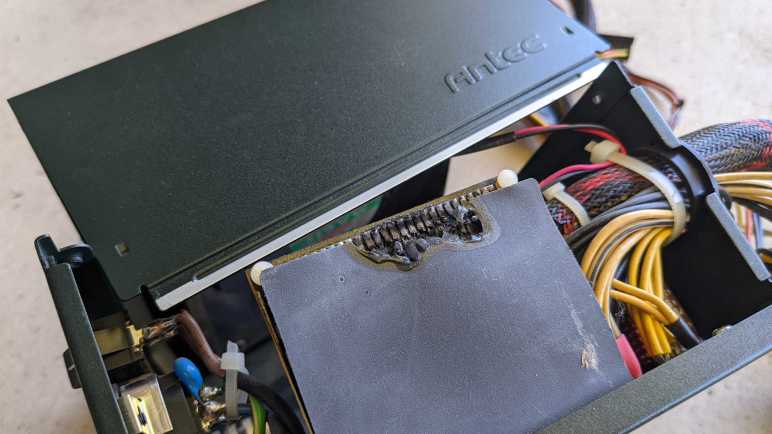
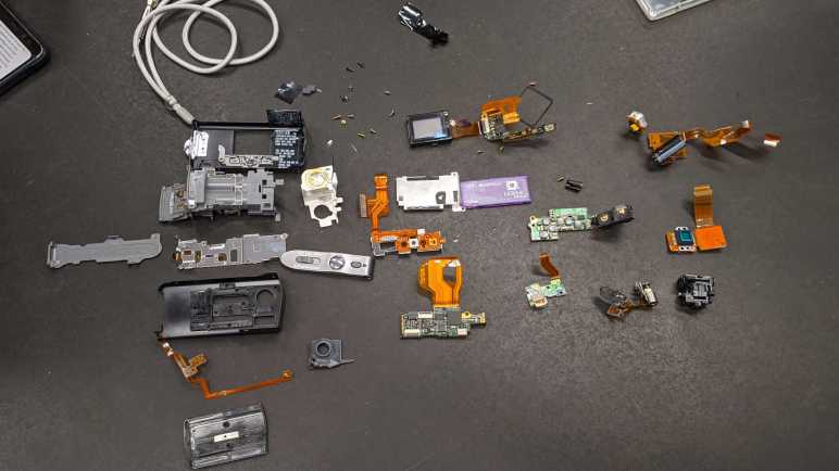
Once I got to remove the back panel, majority of control circuitry became accessible. Only one circuit board is not visible in this picture, as it is mounted in the front for power button and screen.

The large horizontal circuit board has a power-handling section to the right, as indicated by the presence of many transistors, diodes, and inductors. To the left is the brain, including a SanDisk 4GB SD card that wasn’t accessible until the back panel was removed. The smaller vertical circuit board on the right is dedicated to X/Y position control, judging by cables connecting it to the X/Y galvos.

This printer had been shipped around without its original packaging materials, so I had hoped the problem was as easy as a loose connector I could plug back in. Thus my attention was immediately drawn to headers on these circuit board without a wire, but there were no candidate loose wires to plug into those headers. Apparently FormLabs has intentionally chosen not to use those connections, likely related to changes from original Form 1 to this Form 1+.

One of the unused connectors was labeled GALVO Y POWER. I see cables on GALVO Y SIGNAL and GALVO X SIGNAL as well as GALVO X POWER. I guess both galvos are powered from GALVO X POWER cable. This might be relevant to what I find later.

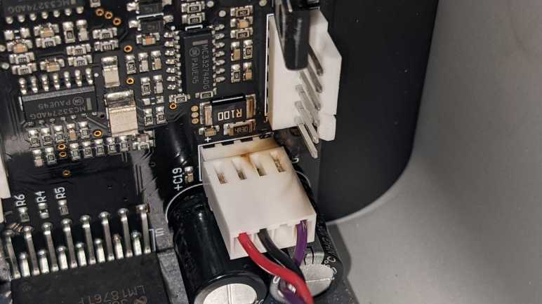
Disappointed that I didn’t find a loose connector I could plug back in or any other obvious easy-to-fix problems, I proceeded to unplug and reinstall every connector to reseat them. Working from left-to-right, everything looked and felt fine until I unplugged the right-most galvo connector. Once it was removed, I got a clear view of the galvo power connector below it.

Discoloration from overheating and possibly soot from a small fire. The toasty connector is the other end of GALVO X POWER. I don’t know enough about this device to say sharing X and Y galvo power from a single connector caused the failure, but it certainly looks suspicious.

I saw no obvious places where GALVO Y POWER could have connected to this galvo control board. I guess it is a later revision that integrated both galvo controls on a single board powered by a single cable. Compare this to Bunny’s earlier device, where we see two separate and seemingly identical galvo control boards, one for X and one for Y, each with their own power and signal cables.

This device is long out of warranty, and official support ended in 2017. I don’t expect FormLabs to have a replacement galvo control board for this Form 1+, but it wouldn’t hurt to ask and see what they say.

Failed LewanSoul LX-16A Servos

I love the concept of serial bus servos, writing them up for the Hackaday audience and designing my Sawppy rover around the low-cost LewanSoul LX-16A serial bus servo. After a few years of actual use, it’s fair to say the honeymoon period is over. LX-16A availability were unreliable even before the global supply chain crunch, and now it’s even worse. Furthermore, the hardware has some really bad failure modes. Two people have experienced failure where battery voltage (~7.4V) get sent out to the USB 5V bus, killing whatever Raspberry Pi was connected via USB. I have firsthand experience where a failed LX-16A shorted battery power to ground, blowing the fuse and required field repair in the middle of Maker Faire. Due to these problems, I intend to move away from LX-16A for future projects.

Now I’m going to open up “FAILED SHORT” servo to look inside. Maybe there’s something visible relating to its failure.

On the upside, the mechanical bits look great. The gearbox used well-lubricated metal gears throughout, and there’s a decent looking ball bearing supporting the output shaft.

Nothing has obviously failed on this side of the control circuit board. The square chip appears to be the main processor. There are four lines of markings on this chip:

HL004
642GB
2634B071
ARM

A web search found this forum thread that identified the chip as a Nuvoton MINI54ZDE, a little Cortex-M0 processor at 24MHz. If I get into playing with ARM microcontroller programming, I might be tempted to connect to the row of five pins and see if I can get a debug connection to that chip. Obviously, if I were to do this, I would use a different LX-16A that doesn’t short power to ground.

The next two largest chips appear to be identical, both labeled with:

4606
GA7N3C

A search found these to be AO4606 MOSFET by Alpha & Omega Semiconductor.

I see no obvious signs of failure on the other side of the circuit board, either. I see an ALPS potentiometer for position sensing, and a 1117-3.3 LDO voltage regulator.

On the upside, the lack of visible failure meant the fuse did its job well, blowing before anything really bad happened to this board. The downside is I have no visual indication of what went wrong. I’m mildly tempted to power up this servo without a fuse just to see what component blows up.

I have another failed LX-16A, this one “merely” stopped moving. It was still communicating with the rest of Sawppy controller system, with all diagnostics information showing OK. Except it doesn’t move. Powering the DC motor directly got me some motion, so at least the mechanical side is fine.

Given the lack of motor movement, I thought perhaps one or both of the MOSFETs have fried. But they look fine on this unit. Nothing’s obviously gone wrong with the CPU, either.

Potentiometer looks fine, and the 1117 LDO appears intact.

These two teardowns failed to provide any illuminating insight. I saw nothing at all that would explain faulty behavior of these units. Looking on the bright side, I’m glad neither of these devices went up in smoke and their mechanicals are still sound. I could still control the mechanicals by replacing these failed control boards with a DC motor H-Bridge controller like the classic L298N or the newer DRV8833. Turning them into a pair of gearmotors with metal gears and a ball bearing on the output shaft.

Electronic Mosquito Trap

It’s summertime in Southern California, which means a surge of mosquito trying to harvest human blood. I do not appreciate being an excellent source of protein, and the weapon I find most satisfying for fighting back are electronic mosquito zapping paddles. Some call them electronic flyswatters but I think that’s a misnomer. At least around here, where our usual species of flies grow far too big to be caught in the mesh.

This one says “Electronic Mosquito Trap” right on the handle. There is an activity light visible through a clear plastic window, and barely readable on that clear plastic is “Little Angel”, possibly a brand. Powered by a pair of AA batteries, the voltage is drastically increased to build up a high potential difference between layers of metal meshes. When a mosquito tries to fly through those layers, they short the circuit ending their bloodsucking quest.

A household commodity made at great volume for low cost, they are practically disposable. This particular zapper was damaged when one of my vigorous swings crashed into the wall. The shattered rim of brittle plastic is cosmetic, but the mesh has also been bent so that the layers touch. It is no longer possible to build a high voltage potential between mesh layers, so it is time for a teardown before disposal.

I expected a voltage boost converter circuit within, implemented in the simplest and lowest cost method possible. I only recently learned to recognize a boost converter when I see one, and this guy certainly qualifies. Implemented with large through-hole components, it looks we have the basics of: a transistor, a coil, a capacitor, and a diode.

Boosted voltage are sent to metal layers via these wires, whose insulation was damaged during assembly at the factory. At least the plastic is still an insulator.

Indicator light wires were also damaged in assembly.

The yellow output wire was connected to the center layer of the mesh sandwich, the two red output wires (both soldered to the same point on the circuit board) are connected to the top and bottom meshes.

Learning more about boost converters is on my to-do list. After I have a better idea of what’s going on, I want to look at this circuit again. Perhaps I can make my own improvements on a mosquito zapper paddle!

OCZ Core Series V2 120GB SSD (OCZSSD2-2C120G)

My first SSD was a Patriot WARP V.2 32GB SSD. It not quite the bleeding edge, that “V.2” signified a revision that solved some issues in the first wave. Early experience with my first SSD was amazing enough for me to look for a larger 120GB unit to gain a little more elbow room in day-to-day use. They both represented early technology with flaws that needed solving before SSD became long-term reliable. I didn’t know that when I bought them, but it was certainly made clear as their performance degraded over a few years and then dying entirely when they no longer showed up as SATA drives when plugged them in. I took apart the first Patriot drive, now it’s time for the second OCZ drive.

Since they were both built around the JMF602 controller and arrived on market around the same time, I expected them to both utilize a JMF602 reference design. Before I opened up this SSD, I expected the circuit board to look identical to the smaller Patriot, just with higher capacity flash memory chips.

I found I was wrong when I opened up the case, this drive used a very different circuit board layout. This design placed the JMF602 at the center, and I don’t see an obvious debug header. There is still a connector adjacent to the SATA data port and it is populated on this drive: a USB mini-B socket that lets this SSD act as a USB flash drive.

Four more flash chips live on the other side of this board, again in a different layout compared to the Patriot drive. They seem to have the same production information sticker, but that might be some sort of industry standard sticker.

Thanks to the USB port, I could still access this drive even though the SATA port no longer enumerates. It is only an USB 2.0 connection, but I don’t think that is a constraint. Write performance has degraded to an atrocious level on this drive. Here I’m copying a single large ISO file to the drive. 25MB/sec throughput and a response time of nearly 500ms are well below limits of USB2.

Read throughput is only slightly better at nearly 40MB/sec and a 20ms read response time is significantly faster but still not great. Since this drive still works via USB, for now I’ll spare it the hot air treatment I performed to the Patriot. But given this level of performance I’m not sure if I can do anything useful with it.

Patriot WARP V.2 32GB SSD (PE32GS25SSD)

When the cost of flash memory dropped low enough for consumer-level solid state drives to come to market, it was a time when multicore multi-gigahertz processors sit mostly idle waiting for data to be fetched from a spinning platter hard drive. SSDs resolved that performance bottleneck and provided a huge boost to overall system performance. But like all revolutionary technology, early implementations had some serious teething issues. Some problems required operating system support like TRIM to solve, which didn’t show up until later.

In those pre-TRIM days, the most affordable consumer-level SSD were built around a JMF602 controller. It helped make SSD affordable, but without TRIM and related functions, those drives weren’t durable. My first two SSDs used JMF602 and both drives died within two years of use. When I plug them into a computer’s SATA port, they no longer enumerate as devices as if they weren’t plugged in at all.

I forgot I had kept those two drives until I found them in my pile of old computer hardware. I might as well open them up before I dispose of them. I don’t expect to see much: just a circuit board inside a 2.5″ form factor metal case. But I was curious if those two circuit boards would be identical: it is fairly common for multiple manufacturers to use the same reference implementation and sell basically identical devices.

First up is Patriot’s WARP V.2 with a paltry 32GB capacity, model PE32GS25SSD.

I found the expected single circuit board inside. The infamous JMF602 chip amongst multiple Samsung flash chips. I see a row of four vias on the lower right edge resembling an unpopulated debug header. (Not that I’d know how to debug this thing.) In the lower left, adjacent to the SATA data connector, is an unpopulated connector blocked off by the metal case. We’ll see this again later.

Four more Samsung flash chips reside on the other side of the circuit board.

I now remember why I kept the drive even after it failed: I had personal data on this drive when stopped responding. Even though it doesn’t enumerate as a SATA device for me, I was worried that the data could still be recovered. Perhaps through that debug header, or possibly a SATA diagnostic tool could unlock it.

Making data really difficult to recover is easy with a spinning platter hard drive: I would open it up to expose those shiny platters. Everyday household dust would render those data surfaces unreadable except to maybe the NSA. But at the time I didn’t know how to perform similar data destruction with SSDs. I had contemplated drilling a hole through each flash chip, but now that I have a hot air rework station, I decided to remove all 16 flash chips from the board. If someone wants to steal my data, they’ll have to decipher how my data was spread across these chips and do a lot of soldering. I may still drill a hole through one of those chips just for curiosity, but first I want to compare and contrast this drive with my second SSD based on the same JMF602 controller.

Makita Ni-Cd Battery Pack (1250)

I took apart an old Makita cordless drill (M651D) to take a look inside. It was very well designed and friendly to servicing, meaning it was easy to take it apart and put it back together still in working condition. The drill is still good, it’s too bad its NiCad battery packs are worn. Which made me think: what if I can hook up another battery to this drill? Since I wanted to leave the drill itself intact, I will remove NiCad cells from the battery pack and solder new wire in its place.

This is easier said than done. While Makita’s DC1414 charger and M651D drill were designed for easy disassembly and servicing, the Makita 1250 battery pack is sealed up tight. There were several YouTube videos of people taking these battery packs apart, and I can see it is glued together all around the perimeter between black and orange plastic pieces. The only way inside is to chisel apart durable ABS plastic.

Fortunately, it appears the battery cells themselves were not glued in place. So I’m going to try a different route and cut from the bottom with my Cutra Wondercutter S. This is not the safest of activities but I’m willing to cut near battery cells because of the following:

  • They have no remaining charge to arc or cause problems.
  • These NiCad cells have a sturdy steel can exterior.
  • Even if I manage to puncture a can, NiCad chemistry is less volatile than lithium-based chemistries.

I would be very hesitant to cut near lithium-based batteries if they were 18650 (or similar) steel cylindrical cells. I would not try this at all if they were soft-skinned pouch cells.

I started with a small cut to find the depth of cut. This also gives me location of a single NiCad cell and lets me get a rough guess of where the rest of them are.

I gradually cut more and more of the bottom away. The Wondercutter does a pretty good job with ABS, cutting partially with its ultrasonic action and partially with the heat generated by said action. There’s definitely the smell of melted ABS but much more pleasant than if all the cutting were done by melting ABS with a heat knife. It does scratch the surface of cells, but didn’t come close to puncturing them.

I had hoped the NiCad cells would just drop out the bottom, but they were actually held very tightly by the base. Around the perimeter are small triangular pieces of plastic that follow the curve of each cell and wedge the entire pack in place. I had to cut all around bottom perimeter in order to remove those wedges. The final two were just inside the plastic clips that I wanted to keep so it could still be installed on the drill.

Annoyingly, those two final wedges were still strong enough to hold all batteries in place! I had to carefully cut away one wedge before I could dislodge the entire pack of cells.

These cells will go to a proper channel for NiCad battery recycle. But before that happens, I want their power contacts.

Those contacts were attached with a battery spot-welder and could be freed with some… mechanical persuasion.

Earlier I took apart a car battery charger, so I had a pair of wires handy and already designed for high amperage around 12V. I soldered them to salvaged battery contacts and reinstalled them inside battery enclosure. Reinstalled back onto the drill, it becomes a corded drill powered by wires. I don’t know what alternate power source I want to connect to these wires yet, but this hack of a Makita 1250 battery enclosure lets me supply power to an unmodified M651D drill.

Makita Cordless Drill (M651D)

A large part of the cost of a cordless drill system are in its batteries, so when this Makita cordless drill wore out its NiCad batteries, it made more sense to get a modern lithium-ion powered drill system to replace this one. Retiring it to the teardown workbench. I tackled the charger first, because I didn’t think there was much point holding on to a NiCad/NiMH battery charger when lithium chemistries have taken over. Next up is the drill itself, which is an interesting comparison to an even older cordless drill taken apart at SGVHAK a few years ago.

The drill itself still works fine. As a powerful motor and gearbox combination with a torque-limiting clutch, I think it’ll still be useful for something, so this is only a partial and nondestructive teardown in order to leave it in working condition. Thanks to excellent work by Makita designers and engineers, this turned out to be extremely easy.

One element of this ease is how this drill was held together by machine screws. Not self-tapping plastic screws, which are cheaper and easier to assemble but weaken every time they are removed and reinstalled. And those machine screws go into captive hex nuts, not heat-set inserts. Together, it means this drill can be disassembled and reassembled repeatedly without weakening. Nice!

After I removed all of the fasteners, I pried the two blue plastic halves apart. As I did so, all internal components fell out. It was startling at the time, but then I was happy to realize that it meant all internals are easily accessible and nondestructively so. Major subsystems fit together without any adhesives or additional fasteners.

I see the planetary gearbox has provision for fasteners to hold it onto the motor, but that provision was not used. It was not necessary: the drill enclosure held them against each other well enough for the drill to function. Speaking of that planetary gearbox, I see a few screws for further disassembly and decided against it. I wanted to keep the gearbox in running order, and I didn’t want the mess of lubricants all over my workbench. Someday I might take it apart to see internal implementation of high/low gear shift and the torque-limiting clutch, but not today.

Control of motor speed and direction is handled by a completely integrated unit. It has solder points for battery terminals on one end, and motor terminals on the other. It exposes two mechanical controls: one for direction, and the trigger for speed. Printed on the side is:

defond
DGT-1225A
25A 14.4VDC

I found the website for Defond and its “Power Tools” division that specializes in making such devices for other companies. I found no listing for DGT-1225A or a catalog at all, implying each product is a custom unit designed and built for a customer like Makita. More useful to me are the ratings printed on the side: up to 25 amps and 14.4V DC. This gives me the power envelope I must keep in mind if I want to incorporate this motor and gearbox into future projects. If I want to put them under a microcontroller’s programmatic control, I’ll need to use motor drivers capable of handling 14.4V * 25A = 360 Watts. Or perhaps I can rig up a different set of batteries?

Makita Ni-Cd Battery Charger (DC1414)

Cordless drills are very convenient to use, removing the worry of power cord management. But the batteries that give them their independence from an extension cord is also their weak point, degrading faster than their mechanical parts. This Makita M651D cordless drill system dutifully served many years, but its nickel-cadmium (NiCad) batteries could no longer hold enough charge to last a work session. Replacement cartridges are available, but it was more cost effective to upgrade to more powerful and longer-lasting cordless drills with lithium-ion battery packs. Which was why this system was retired.

The least useful part of this system is the DC1414 charger, as it was precisely tuned to charge those out-of-fashion NiCad chemistry batteries. I’ll take it apart first.

The charger disassembled easily, no glues or anything annoying held it together. Which is a good thing, because in the lower right corner of the circuit board I see a fuse that requires disassembly to replace. I also see a dotted line across the middle of the board, likely marking separation between high and low voltage areas of this board. I see the logo for Tamura corporation, who Makita apparently subcontracted for this device.

The circuit board is a single-sided design, with through-hole components on the top side without copper traces. On the bottom we see a few surface-mount chips and copper traces, some quite wide for more power-carrying capacity. There is a notable gap across the middle, corresponding to high/low voltage divider line drawn on the other side.

Unusual shapes at several solder joints for high-voltage components caught my eye. In addition to the typical cone shape structure, these solder joints have a five-fingered extension from the base of their cone. Is this intentional or accidental? If intentional, what is their purpose? If accidental, what caused it to happen? I don’t know enough to make educated guesses. The plastic enclosure for this charger will go to landfill, and the circuit board will go to electronic recycle. I shift my attention to the M651D cordless drill itself.

Hardie Irrigation Controller (HR-6100)

I was given this Hardie Irrigation sprinkler controller to take apart, which I’m happy to do.

Color scheme and general design makes it look several decades old. I found nothing that could give it a definitive age, and I’ve found no information about this product online. Its lack of online presence supports the “several decades old” hypothesis.

Flipping up the lower access door we see terminals for sprinklers and a power transformer, a fuse, and two screws. Removing those screws allowed me to remove the core of the device.

Backside of the plastic control panel exposes the plastic ridges that give tactile detents to the selection knob. We also see the front of the circuit board, which has all through-hole components and no traces visible in the front.

All traces are on the back, where we also see the selection dial is not a rotary encoder. It makes actual electrical contact to individual functions.

Returning to the front, I see this is the largest chip on the circuit board. I have no idea what it is, my online search came up empty. [UPDATE: Randy identified the COP444L as a member of the COP400 family of 4-bit microcontrollers. See full comment below for a link to the datasheet. Thanks, Randy!]

The six sprinkler stations are each controlled by one of these. Online search found these to be triacs. I thought it was interesting how we have two of one type and four of the other.

The only item that interested me was the digital illuminated display. These look like old school LEDs. I understand that before manufacturing large LEDs became practical, the only cost-effective option are these tiny little guys. To make them more readable, they are accompanied by plastic bubble magnifying lenses. There appear to be provision for eight digits, but only four are populated.

I see tantalizing hint of more than seven segments in each digit. It looks like there are two center vertical segments so we can go a good “T” and other things difficult with just seven segments. Also, all of the horizontal segments appear to be split to the left and right of center vertical. This can potentially be a 12-segment digit.

However, when I applied my LED tester to various combinations of input pins, I could only illuminate each digit as a seven-segment (plus decimal point) display. I’ll salvage this bubble LED in the hopes I can decipher its secrets later. For now, I see no reason to hang on to the rest of this bulky box and will dispose of them.

Waterpik WP-150W Teardown

My normal home dental routine includes daily Waterpik cleaning, which has been great for my teeth but there’s a cost. Water and electrical mechanics do not peacefully coexist (just ask anyone who owns a boat) which might be why my Waterpik machines haven’t lasted very long. A few years ago I took apart a battery-powered Waterpik that had died, today I am taking apart another.

This one is powered by household AC and it hasn’t quite died. However, it is noticeably less powerful than it used to be. When it was too weak to dislodge a piece of food wedged between my teeth at maximum strength setting, I replaced it with a new unit to restore full teeth-cleaning power. I want to see if I can find any sign of wear and tear that would explain the reduced strength.

An electrical appliance that has water running through it is definitely presents a risk for electrical shock! I’m going to disregard the warning on this bottom label and open it anyway, as I don’t intend to put it back together or run water through it again.

Adjacent to the label is a socket for the handheld wand. Removing the plug unveiled a rubber O-ring seal, which was expected, and this tan-colored flap of plastic, which was unexpected. I see a mesh texture that made me think it might be some sort of filter, but it is not a mesh and seems fully watertight. My best guess is some sort of backflow prevention.

I didn’t expect to find much inside the handheld wand, but I cut it open anyway to confirm. The on/off water flow valve seems fine and there’s no sign of obstruction.

Returning to the base, I removed four Philips-head fasteners between base and enclosure. The strength adjustment knob also had to be pulled out before the enclosure can move.

Inside the enclosure we see a black cylinder where water is fed from a reservoir, and we can see a bit of orange colored sealant to make the joint watertight. The gear-looking thing is for the power switch. It looked and felt like a rocker switch, but it actually has this rack-and-pinion mechanism to translate the rocking motion to a linear sliding switch. If the designers wanted a rocker switch, why didn’t they use an actual rocker switch for household AC? This mechanism feels like unnecessary complexity.

We also see signs of a fine black dust/powder inside, more details on that shortly.

After the sliding switch, AC power is fed through an array of diodes for rectification. A big capacitor smooths output and a resistor drains residual charge from the capacitor after use. [UPDATE: A comment pointed out my mistake, the resistor is not in parallel with the capacitor. It is in series with line input, which is consistent with a resistor for controlling inrush current.] The strength knob has no involvement in the electrical side at all, the motor always runs at full speed and jet strength is a strictly mechanical affair.

I had expected the power to go straight into an AC motor, but that rectifier circuit was necessary as this is actually a 120V DC motor. Something about this DC motor was worth adding the cost of rectification circuit board, I’m curious what tradeoffs are involved.

A disadvantage of DC motors is the need for commutator and brushes, which wears over time. That black dust deposited all around enclosure interior are little bits of vaporized motor brush and commutator flowing out of the motor like smoke, as we can see here. Worn commutator/brushes is the first visible candidate explanation for reduced strength of this device.

Here is the jet strength adjustment mechanism. The spring-loaded gasket at the bottom pushes against the adjustment disc, which has a thin groove through it. It looks like turning the dial adjusts how much of the thin groove is presented to water flow, sapping its strength on longer journeys.

But that is only a guess, because I’m not confident I understand how this system works. Here is the water reservoir intake assembly, which presents two paths for water coming in from the reservoir. One through the holes at the side of a narrow neck, and the other through a spring-loaded contraption for purposes I don’t understand. Once this assembly was removed, I could see the intake tube actually goes all the way through to the exit for the handheld wand.

For the Waterpik to function, all of this must implement a system to ensure one-way flow of water, but I have trouble visualizing how the hydrodynamic forces would interact to make that happen. Disassembling the spring-loaded contraption got me no closer to illumination. Somewhere in here might be the answer to reduced strength as this device aged, but I couldn’t begin to guess how.

The water-pumping piston assembly was relatively straightforward. Motor shaft output is geared down to a crank to move the piston back and forth through its cylinder. No signs of water intrusion and all the lubricants still in place explains why there are no signs of wear or play in the mechanism. Whatever caused this Waterpik to weaken over time, it’s probably not here.

The best hypothesis so far is wear and tear on DC motor brush and commutator. I want to open it up for a look, but the motor is held by these metal tabs bent from the motor can. Roughly one millimeter of steel is too stout for me to bend out of the way with pliers.

Which means it’s time for the Dremel cutting disc!

Once those two tabs were cut out of the way, I could remove the white plastic end cap and see the motor commutator and brushes. They are very definitely worn, but I wouldn’t have expected this level of wear to cause a severe degradation in output power.

This Waterpik base managed to keep a few a secrets even when disassembled. I still don’t understand the complexity of how water flow is restricted to be one-way, and I failed to find an obvious explanation for a weak output jet. At the rate I’m wearing them out, though, I’m sure I’ll have another opportunity in a few years.

Microsoft Arc Touch Mouse Surface Edition (Model 1592)

I love Microsoft’s Arc Touch Mouse. It seems like one of those fancy design concepts that never make it beyond a rendering, but it is actually a real product we can buy. A Bluetooth computer mouse that is also a transformer that flattens for easy portability? I thought it was so cool, I bought one of the early versions: Surface Edition model 1592. Looking at the latest edition, I see they now have fully capacitive touch surfaces. Mine had two physical buttons for left and right click, and a touch surface in the middle to emulate a mouse scroll wheel and center button.

I would not have been surprised if the collapsible mechanism failed after years of use, but it has actually proven very durable. My problem is the forward section plastic which has degraded and oozing a sticky liquid I could not clean. It captures dust and dirt, and leaves my finger sticky after I touch it. It feels unpleasant so I don’t use it as a mouse anymore, making it an ideal teardown project.

Note: There will be some inconsistencies in these pictures. Partway through this teardown, I finally saw enough of the internals to realize I did not take it apart in the optimal order. I’m presenting these pictures in the order I should have used to take it apart.

Arc Touch Mouse has a smooth and unornamented exterior. All the legal requirements and identifiers are on a label inside the battery compartment.

Peel off that label to unveil a set of debug/test points and two T5 screws.

Removing them releases the top button surface, though it is still attached by two cables.

Disconnecting a ribbon cable and a two-pin haptic feedback connector will allow the top to be removed. I set this aside for a closer look later.

Once the top is removed, we can safely remove four screws holding a bracket for the rubber skin in place. Once freed, the flexible portion should be something we can peel off like a sock. Of course, I had already cut it apart with a knife by the time I realized this, so I’m not sure. Only the bracket itself is left visible in this picture as I had already cut the rest of the rubber sock away.

With the rubber sock removed, we can see the transformer mechanism. Holy parts count, batman! There are ten plastic segments to this mechanism, held by flexible spring steel top and bottom fastened by screws and plastic rivets. I did not expect this much complexity.

All of those parts were necessary so the mechanism can take one of two positions.

Top sheet of steel is fastened by melted bits of plastic forming rivets. The bottom is a four-sheet assembly so they could slide past each other as the mechanism curves. Under those four sheets is a long strip of copper-colored metal which is the key to how this mouse can hold one of two distinct positions. A strong magnet lives in a cavity at the end of the curvature, with two bits of steel at either end. The magnet wants to be up against one of those two pieces of steel, which corresponds to the flat and curved positions of the mouse. This is very clever! It also reminds me of another magnetic mechanism a convertible tablet used to stick to its keyboard dock.

The curved/flat transforming mechanism is also the power switch for the mouse, implemented as a tiny little thing adjacent to the magnet cavity actuated by a right-angle fold in the copper strip. I am amused that they had to make a circuit board just for the sake of hosting this surface-mounted switch.

Returning to the top plate, most of the complexity here is centered on the capacitive touch strip in the middle. At the lower right, we have a side-lit LED activity indicator. Behind the circuit board is a long rectangular haptic feedback device. Printed on this flexible circuit is the following:

Foxlink CO., LTD.
CONFIDENTIAL
Dali_Capsense
V2R1+

I infer “Dali” was the development codename for this device.

I tried to extract the capacitive touch flex circuit intact, but I unintentionally ripped it in half.

Before this teardown I had assumed the haptic feedback came from a motor with an eccentric weight on its shaft, common for cell phone vibrations and such. This device was too long to be a spinning motor, so I wanted to see inside. It was wrapped in no less than four layers of sheet metal. So thin, they were barely more rigid than paper and practically razor blades. I had to be very careful peeling them apart to find a small coil-wrapped armature between two magnets.

The mainboard of the mouse is almost boring in comparison to the rest of this device, but it does confirm the Dali name with:

Dali
Navigation_V2R0

I was surprised to see that the mouse position optical sensor is separate from its illuminating LED instead of together in an integrated enclosure. I briefly thought about removing the sensor for novelty’s sake, but these things are tiny. I decided not to spend time getting something I’ll lose the next time I sneezed.

This was an epic teardown. The Microsoft Arc Mouse is a premium product, significantly more expensive than lowest-bidder Bluetooth mice on Amazon. But I love its novel design. After seeing all its components, I’m actually surprised it isn’t more expensive. In fact, I’m surprised it got approved for manufacture at all! I wonder if mechanical engineers have managed to simplify construction of current generation Arc Mouse, but they are too expensive for me to buy one just to take apart. Perhaps someday I’ll have a chance to pick up a broken unit and take it apart for comparison.

Black & Decker Clothes Iron (IR0175W)

The main job of an iron is to make a flat piece of metal hot so we can use it to flatten wrinkles in our clothes. This particular iron was retired when it could no longer reliably do that one job. When plugged in, it would get hot as expected. Once it reached a certain temperature, it would slowly cool down, which is also expected. But it failed to turn the heat back on quickly. This iron would cool to almost room temperature before it would heat itself back up. I tried to find other use for it, but I’ve decided to take it apart. If I can fix it great, if not I will dispose of the remains.

No manufacturing date was visible on the product label. We see the old Black & Decker logo and searching for this model number IR0175W returned no results. Judging by appearance I would guess it is roughly twenty years old, because Apple made this “Bondi Blue” color cool in 1998 with the original iMac. Within a few years, everything made of plastic was available in this shade of translucent blue alongside white plastic.

The only externally visible fastener was a Torx 10 screw just below the power wire. It’s even a “security” Torx with a little post in the middle. It was quickly dispatched so this back plate can be removed revealing ordinary Philips head fasteners for the remainder of this teardown. “This would be easy!” I thought.

I was sadly mistaken. I couldn’t figure out how to remove the top plate elegantly and resorted to brute force. After it was torn off, I saw it was secured by a Philips fastener that was hidden under the steam pump button. (See green rectangles in above picture.) This button had plastic clips so that, once installed, it could not be removed. I see no way to open this without damage. This external enclosure is ruined, I’m not going to be able to fix it and put it back together.

The circuit board in the handle is interesting. It had 120AC line (red, labeled L AC2) and neutral (blue, labeled N AC1) coming in, and an output line (yellow, labeled OUT). The yellow and blue wires connect to the body of the iron, so this blue rectangular relay is definitely capable of switching the heat on or off. However, it is not in charge of temperature control, because there is no way for it to sense the current temperature or read the user adjustable temperature setting dial. This circuit board does have a mechanical sensor of some sort in the black rounded enclosure visible just to the right of the blue relay. It makes sounds when I shake it that is consistent with a little metal ball inside. I hypothesize this circuit implements the safety timer. If no motion is sensed over a time period, turn off the heat.

Removing the top deck and temperature dial revealed the Bondi Blue water reservoir. We can see the top end of the temperature regulation mechanism where it connected to the temperature dial.

Not much new is revealed once the water reservoir was removed. I was amused to notice that the reservoir was installed incorrectly at the factory. We can see the orange water gasket leading to the hot bits was crushed out of place for roughly one quarter of its perimeter. Thankfully I never noticed a leak from this error, though I didn’t use the steam function very much anyway.

The bottom-most layer in this stack: Heating elements permanently enclosed and bonded to the metal ironing surface. The temperature regulation system is fastened to the top of this layer.

Temperature regulation is a mechanical system centered around a bimetallic strip. Simple in theory: the circuit is closed to heat things until the strip changes its shape and opens the circuit. The system closely cools until the strip changes its shape again to close the circuit and repeat the process. Turning the heating level knob (top layer) I see it is a threaded contraption that ends in a white insulator point pushing on the second layer. Turning the dial subtly changes the bimetallic strip assembly geometry so it changes shape at different temperatures.

I turned the dial back and forth through its range of motion (~270 degrees) and I could see and hear the bimetallic strip pop back and forth. I did this a few times before I realized… wait, that’s not supposed to happen! This thing is at room temperature. A clothes iron shouldn’t be turning its heating element off at room temperature. This behavior is consistent with the observation this iron cools off too much before heating back up. I assert this bimetallic strip should remain at the closed position through the entire range of this dial at room temperature. But the only candidate for adjustment is a tiny flat head brass screw at the top of the dial, securely fastened by a blob of adhesive. I managed to damage the brass before I made any progress breaking that adhesive blob, ruining my chances of fixing it. This teardown was instructive but ultimately a failed repair. I disposed of the remains and moved on to the next teardown.

Evaporator Fan Motor (ADL-5846AMEA)

I took apart a microwave oven turntable motor and found it surprisingly simple. Encouraged, I dug through my “take apart later” pile for another appliance AC motor and found this item.

Sticker says:

2940rpm 0.14A
ADL-5846AMEA 12732601
115V 60Hz 4.6W Z.P CL.A
SUNG SHIN 030307

Searching for “ADL-5846AMEA” found this was an evaporator fan motor, meaning it was responsible for circulating cold air in a refrigerator. While we don’t care which direction a microwave turntable turns, the direction is very important for a fan motor. Given this fact, and assuming reliability and low cost would be the driving factors in the design, I had expected to find a shaded-pole motor inside this housing.

I was wrong! It was far more complex inside than I had expected. There are four distinct coils mounted to a circuit board with roughly a dozen other components. Through-hole capacitors and diodes are mounted on the same side as the coil.

The opposite side are mostly surface-mounted components, with two large prominent field-effect transistors (FET1 and 2). For me, the most unexpected component is the label box up top:

HALL IC
-4° SHIFT

Wow, there is a Hall-effect sensor on this board, too?

There it is, nestled between but slightly offset from the center point between those coils. Its presence means this control circuit has feedback on rotational speed of this motor. This can be something as simple as detecting a stall, or as complex as variable-speed control. This motor has only two wires for power input, leaving no provision for communicating speed control. Therefore if the hall sensor is for speed control, that control logic must be completely encapsulated inside this module. But following copper traces failed to find anything that resembled a digital microcontroller. I guess it is a completely analog control circuit, which is indistinguishable from voodoo magic for my current level of knowledge.

Why would a refrigerator need such complexity in a fan motor? There must have been a requirement that was deemed more important than “lowest cost” and my best guess is efficiency. Wikipedia claims shaded-pole motors are only about 26% efficient, and the rest would have turned into heat. Waste heat is especially bad for an evaporator fan motor that sits in the cold loop of the refrigerator. Making this motor more efficient reduces workload on the cooling system, helping the refrigerator meet Energy Star and other similar requirements around the world.

The two motor shaft bearings would have been another tradeoff between cost and efficiency. The motor shaft has a bearing assemblies front and back to reduce friction, which reduces heat and increases efficiency. It is more complex than a simple oil-embedded metal sleeve bearing and less complex than a roller bearing. My fingers could feel that the soft absorbent pads are oily, but I’m not sure what I’m looking at. Are they intended to serve as additional oil reservoir for the metal sleeve? Or are they supposed to draw oil out of it? This evaporator fan motor teardown was full of surprises, from the control circuit board to this bearing assembly. I love it.

Microwave Turntable Motor (TYJ50-8A19)

Today’s teardown subject is a motor that once spun the turntable inside a microwave. Emily Velasco salvaged it from a broken microwave and reused it in a kinetic sculpture named Dark Star.

Sadly, Dark Star met an unfortunate end when it fell off the wall. Among the debris was this motor, its output shaft now severed. I asked for the damaged motor so I could see what’s inside.

Information was stamped into the front and back of this motor. I read the following information on the front:

SYNCHRONOUS MOTOR
TYJ50-8A19
Heng Xing
RoHS
CW/CCW
E199324
100/120V ~50/60Hz 4W4/4.8 R.P.M.

And on the back:

TYJ50-8A19
120420

Since “TYJ50-8A19” was stamped on both sides of the motor, I used that for my online search. Multiple Amazon vendors offered to sell very similar but not identical motors(*) and there were eBay and AliExpress vendors as well. (Some even have metal output shafts, which might have survived the fall.) Most of the listings described them as microwave oven turntable motors, some listings even had explicit model numbers of microwave ovens that used this style of motor. I guess “TYJ50-8A19” was the model number used by a specific manufacturer, but it has since been copied by others and became a generic designation. (For another example, see 28BYJ-48 unipolar stepper motor.*)

Front face of this motor was held in by the outer casing pressed inwards at four locations. Bending those tabs out of the way freed the face, showing this geartrain. The lubricant in this gearbox seem to get darker and more viscous (thicker) as we go from motor rotor towards output shaft. I can’t tell if this is because multiple different lubricants were used, or if this is the same lubricant responding to different stresses in use.

Flipping over the broken output shaft, I see broken plastic on the back side as well. Given how low the costs are for these motors, I doubt I could find replacement gears. The strength and precision required to replace this gear is beyond what my hobbyist FDM 3D printer is capable of, so I can’t make my own. If I had a resin printer I could emulate the shape, but I’m not sure if hobbyist level resins are strong enough. Another concern is the lubricant, which might damage certain resins.

There were six moving parts in this motor: the output gear/shaft, the rotor with a ring of permanent magnet mounted to a blue plastic hub, and four gears in between them.

A metal plate in the middle of the motor held four metal pins acting as axles for each intermediate gear. The axle for the rotor is a similar metal pin mounted to the outer shell. The output shaft which I had expected to receive the most stress does not have a metal axle shaft, a curious design decision that probably contributed to this motor’s demise.

Below that plate is… a single coil? This was unexpected. From the Wikipedia article for synchronous motor, I had expected to see multiple coils. Most of my teardown experience to date have been with DC motors, so I didn’t know quite what to expect with this AC motor. Given its price I knew it had to be simple to manufacture, but I hadn’t known they could be quite this simple in construction.

If it is indeed a single coil connected directly to the single phase of household 60Hz 120V AC, it would generate a magnetic field that flips polarity at 60Hz. In theory I understand that’s enough to get a rotor turning, but with a single phase there’d be no control over which way the rotor decides to start turning. This fits with the “CW/CCW” stamped on this motor, and ideal for the microwave turntable use case where we don’t really care which direction it spins.

But to make it work, what kind of magnetic field does this rotor’s permanent magnet need? In my mental model, aligning the magnet’s north/south poles to the rotor axis wouldn’t impart a rotational force as the electromagnetic field oscillates, neither would aligning the poles perpendicular to the axis. Now I’m curious and I want to visualize this particular magnet. I could buy a sheet of magnetic viewing film (*), or some ferrofluid(*), or some iron powder/filings (*). Or perhaps I could make my own metal filings? That will be a project for another day. Right now, I want to build on this experience and take apart another appliance motor.


(*) Disclosure: As an Amazon Associate I earn from qualifying purchases.

Antec ATX Power Supply Failure (EA-650 Green)

As an electronics hobbyist, I am quite familiar with the smell of fried electronics and burnt plastic. But I usually smell them immediately after I made a mistake, not waking up to that smell in the morning. I shot out of bed looking for the source, thinking one of my projects died overnight. But it wasn’t one of my projects. The smell was coming from my TrueNAS CORE server, which was surprisingly still running. After I properly shut it down and disassembled its power supply, this is what I saw:

Not good, something got hot enough to melt a hole.

The heat source appears to be this row of surface mount resistors. While a resistor is expected to turn electricity into heat, they’re not supposed to get this hot.

There are no components on the other side of the circuit board behind those transistors. Just a few identifiers “2960323904” and “DC-3266”.

The scorch marks left inside the power supply enclosure imply they got hot enough to start burning, which was thankfully contained within the enclosure and did not turn into a house fire. Hooray for electrical fire safety regulations! However, I’m concerned at the fact that it caught fire at all, as I would have the power supply to shut down when something goes wrong. Every one of my previous failed power supplies would shut down and refuse to run again, but this one kept running merrily along even after it had (briefly) caught on fire!

There were no signs of damage beyond this vertical riser circuit board. I saw nothing I recognized as a fuse, though I’m sure there are form factors I don’t recognize. [UPDATE: I took apart another computer power supply and found it died from a blown fuse. The fuse was very hidden and definitely not designed to be user accessible. Once I found the fuse in that other power supply, I was able to return to this power supply and find its non-user-serviceable fuse as well. This fuse did not blow despite the fire.]

No sign of overheated traces on the circuit board.

This power supply had been running quietly and reliably for years, powering my TrueNAS CORE server. My Kill-A-Watt meter indicated a steady-state power draw of roughly 80-90W, which is a tiny fraction of this power supply’s advertised 650W capacity.

I don’t remember how long I’ve had this power supply, but I am confident it is well out of warranty. The only date stamp I saw was on the back of the cooling fan, with a manufacturing date of December 13th, 2011. This puts an upper bound on the age.

Random side note: I think “Protechnic” is a perfectly reasonable name for an electronics supplier company. Given this episode of combustion, though, I also note it is just one unfortunate letter off from “pyrotechnic“.


CL84209 Handset LCD Disassembly

I’ve mapped out the custom segments that occupy the lower half of this LCD, from the handset of an AT&T CL84209 cordless phone system. With that knowledge in hand, I wanted to dig a little more into this subassembly. When I removed it from the handset circuit board, I saw tantalizing hints of identification information that was mostly illegible through distorted plastic.

Four small sheet metal loops stamped in as part of the top metal shield held this assembly together. Once I popped those four loops freed of the tabs molded into the bottom-most piece of plastic, I could lay out all of its layers.

From left to right (bottom to top) we have:

  • Glossy injection-molded plastic bottom layer that is also most of the structural support.
  • Thin matte sheet of plastic.
  • Thicker (~1mm) clear sheet of plastic acting as conduit to distribute light from the single LED.
  • Thin frosted sheet of plastic acting as diffuser.
  • Glass LCD assembly with built-in I2C controller somewhere under the black blob.
  • Rubber surround (glued).
  • Topmost metal shield.

And now the objective of the exercise: a clear view of everything printed at the bottom of this handset LCD. Printed on a sticker is the following:

GWMS7728B
09470315313

Printed on the Flexible Printed Circuit (FPC) is:

7728-FPC-B-A152-4709

I see the logo of stylized “LCD” on both the FPC and etched into glass.

I saw the same logo on the base station LCD. And whereas that module was designated 6334, this one is clearly designated 7728 based on that number being repeated three times: etched into a layer of glass, on the white sticker, and also on the FPC connection.

This is a lot of additional information! Unfortunately, more information doesn’t guarantee success. Armed with this additional data, I still failed to find any details on this LCD module. But I’ll leave them here as a record hoping that my search skills will improve enough in the future to find something. But for today, I have to concede that I’ve tried everything I know. Lacking an official reference, I can only summarize all of my guesses about this device.

Quadrature Encoder Rotary Knob with Detent

In order to create a segment map for a salvaged LCD unit, I soldered a rotary knob into my Arduino circuit so I could interactively select which segment to activate. It came from this particular Amazon multipack listing (*) which was the lowest bidder that day. This knob reports rotary motion via quadrature encoding, and it has a mechanical detent for tactile position feedback. (Twenty detents per revolution of the knob, or 360/20 = 18 degrees per detent.) It also responds to push like a button. The segment map project was my first unit from the multipack, and it seems to function properly. Even better, it doesn’t “feel cheap” in its tactile sensation, so I’m happy with this particular multipack. And because it was so inexpensive, I decided to take one apart and look inside.

The entire assembly is held together by folded sheet metal. Bending its four fingers aside allowed me to separate the device into individual subcomponents. The pushbutton mechanism is at the bottom, a very simple construction where the two pins connected to two sheets of slightly separated metal. There’s a slight convex curve to the metal acting as spring. Pushing on the knob pushes these two sheets together. Overcoming the convex curvature gives us the tactile “click” of the button press and gives us electrical conductivity between those two sheets. Usage: tie one of these two pins to ground and connect the other pin to the microcontroller input pin with either internal pull-up or external pull-up resistor so it normally reads high. When knob is pressed, the pin will be shorted to ground so it reads low.

The next layer up is the quadrature encoder to report rotary motion. There are two sets of thin metal fingers that stay in a fixed position, making contact with alternatively conductive/non-conductive portions of a wheel that turns with the knob. Here is an illustration of the electrical conductivity between these fingers and their interface pins:

The center of these three pins connect to both sides. Each of the other two connect to their side of the wheel. Usage: connect the center pin to ground. Connect the other two pins as quadrature A and B signals to microcontroller with internal pull-up or external pull-up resistors.

Above the wheel is the detent mechanism. For this particular device, there is a detent every four quadrature transitions. When it is stopped at a detent neither of the two side pins are connected to ground. (high/high) When turning from one detent to the next, it will quickly cycle through the other three states (high/low + low/low + low/high. Or the reverse order low/high + low/low + high/low if spin the opposite direction) before stopping at high/high again on the next detent.

These quick transitions meant polling would not be fast enough to read this encoder. We require hardware interrupt support to ensure we don’t miss steps. As I did for the Toyota faceplate investigation, I used Paul Stoffregen’s Encoder Arduino library. This time running on ESP8266 Arduino Core instead of ATmega328, it reliably read knob transitions using ESP8266 interrupts.

(Note: at the time of this writing, the latest public release is v1.4.2 which has problems running on an ESP8266. I had to clone the repository directly to pick up at least this fix among others.)


(*) Disclosure: As an Amazon Associate I earn from qualifying purchases

Electric Blanket Control (Sunbeam PAC-215)

Electric blankets are an energy-efficiency way to stay warm during cold nights. If I’m going to stay in bed while sleeping, why heat the whole house? Heat just the bed and get a comfortable rest. But they don’t last forever, and this particular Queen-sized blanket stopped heating for unknown reasons. I’m going to take apart its two control units (one for each half of the bed) to see what’s inside.

According to the label, this is a Sunbeam PAC-215 STYLE 85KQP with a maximum power draw of 360 watts. I interpret PAC-215 to mean the functional designation and 85KQP to mean a specific cosmetic variation, but that’s just a guess. (And it doesn’t affect a teardown, anyway.)

Peeling back all the adhesive circles unveiled two Philips-head fasteners.

Once those two fasteners were removed, there were three plastic clips to undo before the bottom could be separated from the enclosure. We see many thick traces and wires of through-hole components. Four small Philips-head fasteners hold the circuit board in place, the larger fifth fastener is for the heat sink and can be left in place.

In addition to those four fasteners, the LCD is held by two plastic clips and blobs of hot glue.

Once removed, we could separate the circuit board from the enclosure. Curiously, I see a sheet of metal glued to enclosure top conducting from one of the four screws out to the front of the display area. It might be for grounding purposes, but there is no other metal for it to make contact. It’s not obvious to me what user scenario justified this effort.

I was amused to see that backlight for the LCD is just a pair of LEDs soldered to the board. Simple, straightforward, and functional. No fancy multi-layer light diffusers for this screen.

The circuit board has a white silkscreen marking of PEP003-0A.pcb on the left and a copper marking of FR4(94V-0) DD2 REVB on the right. This picture was rotated 180 degrees relative to earlier pictures to better read identifier on the large surface-mounted IC.

DD2ZW2-3
MP9ACO218E
KOREA

I can make out the ST logo but a search for “DD2ZW2” and “MP9ACO218E” on their site both came up empty. Based on the traces going directly to the LCD, this chip has LCD control capabilities. How much more? I don’t know. It might be a complete electric blanket controller solution for all I know. The other item with a ST logo is a BTB06 triac.

I then proceeded to disassemble the other controller, whose enclosure came apart the same way. I had expected to find two different circuit boards: a primary controller with majority of logic and a secondary unit purely for user interface purposes. I was wrong: the two circuit boards are identical. They only differ in how wires were soldered to each board. I followed their paths and drew a crude diagram.

The power plug enters the first unit and connected to points labeled “H” (Hot) and “N” (Neutral). These are forwarded to the second unit as H2 and BN, respectively. H2 enters the second unit at its own “H” and BN goes to the second unit’s “N”.

Outputs of the first unit are labeled BH and BS, which enters the second unit as BH3 and BS2, respectively, and forwarded on to exit points BH2 and BS. The second unit’s own output goes out as BH, and neutral is forwarded out to the blanket plug.

The blanket plug itself was interesting. It was made of injection-molded plastic and designed to allow loose tolerances due to the flexible nature of the plastic yet still offer lots of mechanical strain relief.

The story continues inside, with plenty of strain relief considerations. This should nearly eliminate any mechanical stress from acting on the four crimped electrical connectors.

This teardown was more interesting than I had expected, as the controllers were more sophisticated than I had given them credit for. That was fun in its own right. But the motivation for doing this teardown today (instead of later) was so I could get my hands on some simple bare LCD modules I could play with.

Cen-Tech 12 Volt Battery Charger/Maintainer (99857)

I don’t know why this particular battery charger/maintainer was discarded, but I wasn’t going to hook it up to a real battery to find out. I got it from a discard pile just to take apart and look inside. It was designed to be permanently mounted under the hood of a car. When we want to charge/maintain the battery, we plug an extension cord into its stubby power cord.

Harbor Freight no longer lists item number 99857 on their site. I also note that this label (and all the warnings) would not be visible when the device is mounted.

Disassembly was straightforward with only four screws to remove.

It’s almost refreshingly retro to see a circuit board with only through-hole components. It also meant I could easily follow circuit board traces to see how much I understand. My first impression (and assumption) was that the big coil in the middle was the transformer, and I had thought it was used to step the voltage down from household 110V AC to something lower, then passed into a rectifier to obtain DC voltage somewhere near the 14.4V maximum for lead-acid battery. But I realized I was wrong when I followed the copper trace for the line voltage. (White wire.) It first goes through a nonreplaceable fuse (better than no fuse I guess) and then immediately into the rectifier. The DC output — which I guess would be above 100V DC — is buffered by a big capacitor, and I don’t understand very much beyond that. I understand a little more every time I do a teardown, so hopefully I will be able to decipher more if I return to this device in the future.

Sony Cyber-shot DSC-U20 Digital Camera

Twenty years ago, photography’s film-to-digital transition was well underway. Designers and engineers were pushing the limits of what they could do when freed from the constraint of a roll of film. The landmark iPhone wouldn’t be released for another five years, ushering in the age of everyone having a touchscreen cell phone (and an attached camera) in their pocket. This was the golden age for small digital point-and-shoot cameras, as it was between the age of film and era of ubiquitous phone cameras. In this environment Sony announced an ultra-tiny digital photo camera, the DSC-U20. Some reviewers claimed it was smaller and better than the best film cameras ever made for clandestine espionage, which sounded great but how they could possibly know?

Anyway, when I learned of it I was blown away by how small it was. I remember thinking if I took a canister for 35mm film and made it 150% as long, it would be approximately the same size as a DSC-U20. Enchanted, I had to have one despite its expense, and my income at the time allowed such frivolous purchases. It was small enough to carry every day, a handy camera years before everyone’s cell phones had a little camera.

If we looked at this device today without that historical context, one could be forgiven to think Sony just packed a cell phone camera into a case with battery and called it a day. That would be very, very wrong. It was a marvel of engineering and packaging, with electronics crammed into every available nook and cranny connected by flexible printed circuit boards. Flex PCB is something easily accessible to the electronics hobbyist today, but not twenty years ago.

The sun had since set for compact point-and-shoot digital cameras. Some people still have them and list them on eBay as “rare vintage digital camera” asking hundreds of dollars for them. Feh! Taking one apart is more fun. I brought it to the January 2020 session of Disassembly Academy at Supplyframe Designlab and a team went to work. I was running around as a co-host of the event (taking a few pictures along the way) and as much as I enjoyed sharing my love of taking things apart to see what made them tick, I was a little sad I couldn’t see every minute of this teardown.

The tiny camera took up more and more of the table as it slowly disintegrated through the night.

I took this picture at the end of the night, showing all the major subassemblies. To this day, this is my favorite picture out of all Disassembly Academy projects.

Two of the participants wanted to take a souvenir home each, a request I happily granted.

One participant took home the rear user control subassembly including the display unit. (Top red rectangle.) I had the impression that this tiny screen was one of Sony’s first attempts at a commercial OLED display, but what we saw was consistent with an LCD. Either my memory is faulty, or we have no idea what an early OLED should look like.

Another participant took home the CCD imaging sensor. (Right red rectangle.) Unlike modern cell phones with their CMOS imaging sensors, this camera had a much bulkier and power-hungry CCD as a tradeoff for better image quality.

I took home the rest, planning to take a closer look at the components later. This is the day.

This camera’s component packaging is even more impressive when taking into account of the fact that more than half of the interior volume were consumed by the battery tray (a pair of NiMH AAA recommended to sustain current draw) and a slot for Sony’s proprietary Memory Stick.

The battery terminals are connected to a power control board with many inductors, capacitors, diodes, and transistors visible. A high density BGA IC is in charge of this department.

Significantly more electronic brainpower lives on this main board, with connections to nearly every other flex PCB on the device. The largest chip has a Sony logo and, based on my past experience tearing down Sony products and encountering plenty of their proprietary components, I didn’t bother wasting time trying to look up that chip’s designation of CXD3159 304A38.

Today, white LEDs are bright enough to add light to the scene. They’re not a true flash but they consume far less power and space. This camera predated such high-powered LEDs, so it had a real Xenon flash with capacitor and its own power control board taking up precious volume for the sake of making a bright flash of light.

Here’s the tiny lens assembly, with a lens that can slide on tiny linear guides. Early cell phone cameras had fixed lenses and all the limitations that imposed. More recent cell phone cameras had lens elements that are moved with voice coils.

Not this camera! Four electrical contacts each imply this is a pair of tiny stepper motors for controlling aperture and focus.

One of the two aperture control flaps has been lost.

Focus control motor shaft has a cam for lens position, working alongside an optical end-stop sensor for lens position.

It might be fun to get these motors to run again, but I’m confident the stepper controllers I have on hand for NEMA17 sized stepper motors would instantly burn these little guys up. Even at their lowest current limited setting. I’ll wait until I get my hands on something that can enforce a lower power limit before I try moving these motors.