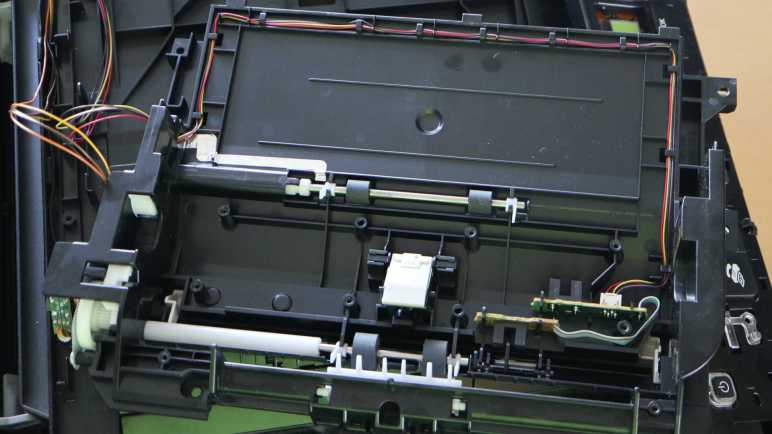
I know I haven’t uncovered all of the paper handling mechanisms of this Canon Pixma MX340 I’m taking apart, but I’m already impressed with the partial overview I’ve got so far. Right now my focus is tracing those paper feed rollers back to the motor gearbox driving them.
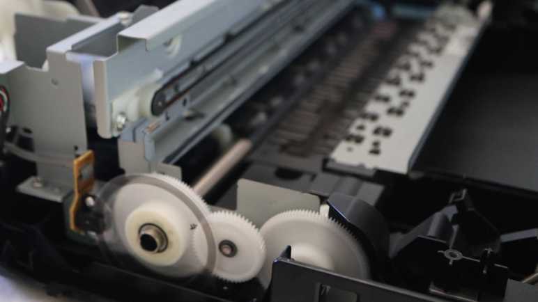
There are two paper feed rollers visible here, one before and one after the printing area. Each of those roller shafts are attached to a large white gear. A smaller intermediate gear sits between them to drive both. Earlier I had thought the motor must be behind that center gear, but it turned out the motor was actually a little lower.
The motor output shaft has a small black plastic gear, almost blending into the shadows. I traced only two wires leading into this area, implying it’s a brushed DC motor down there. Some of the older inkjet printers I took apart earlier used stepper motors for open-loop control. In this printer, precise control is accomplished with a closed-loop control system: the gear on the left has an encoder wheel and a sensor reading its motion providing feedback.
Flipping my camera lens to “super macro” mode, I got this close-up picture of the encoder ring. It is series of very fine evenly spaced radial lines, consistent with an incremental encoder. I see four wires leading to the sensor, consistent with things I expect to see: power, ground, A, and B. I’ll hook them up to my oscilloscope later to verify this deduction.
This motor drives a lot more than the two paper feed rollers immediately adjacent to the print area. One of the paper feed rollers transmit its power all the way across the printer to a gearbox behind the print head parking area. It’s likely involved in feeding paper from the input tray, and others I look forward to deciphering later. Right now, though, another interesting feature of this printer is immediately adjacent and accessible.
I’m taking apart a Canon Pixma MX340 multi-function inkjet and it took a while to work my way down to the actual printing mechanisms in its base. There were a lot of interesting parts near the print head parking area, including a mystery gearbox I can’t access until later. For now I know only it has several gears and a photo interrupter sensor, and it’s involved in the paper feed process.
One of the gears is connected via a shaft to the paper feed roller, which has its own corresponding spring-loaded lever + photo interrupter sensor to detect when a sheet of paper has been fed through.
The tired old paper feed roller is covered with cracks.
The paper feed path design for this printer is nearly straight, barely bending the sheet of paper as it is fed from the input tray in the back through to the printing area and the output tray in the front. Here we can see two more sets of rollers, one immediately before and immediately after where the print head deposits ink.
Between these two sets of rollers, underneath that print area, is a sponge-looking substance that has soaked up a visible quantity of ink. The surrounding plastic shows plenty of ink stain discoloration as well. I can’t explain all of the reasons why ink ended up here instead of on paper, but I know one explanation are from my border-less photo printing on 4″ x 6″ glossy photo paper. In order to not leave any borders, the print head shoots out extra ink beyond the paper’s edge. That ink had to be go somewhere and we’re looking at them now.
Now that I know excess ink may get sprayed around even during normal usage, I started noticing ink absorption pads scattered throughout the print engine. I remember reading consumer backlash against Epson EcoTank machines. Advertised to be ideal for high volume inkjet printing, some users were surprised when their machines stopped printing. They had encountered a preprogrammed expiration for ink pads reaching end of life. At the time I agreed with many others online thinking it was just corporate greed shutting down perfectly working printers, but now that I’m looking at these ink pads on my old printer, maybe it’s a good idea to avoid overfilling their diapers.
The second set of paper feed rollers helps keep the paper straight during printing, and can help eject the printed sheet at the end. But it needs to solve an unique problem: how does it handle the printout when the ink is still damp immediately after printing? To see how that was done, I unscrewed the top set of rollers and flipped over the mechanism for a closer look.
The top rollers are actually small stamped sheet metal spiked wheels that minimize contact area with the just-printed surface. Thereby avoid smearing still-wet ink as the paper travels through these rollers. Very nice! Next I will look at the motor and gears driving this paper feed mechanism.
The flatbed scanner module of this Canon Pixma MX340 multi-function inkjet turned out to be mostly empty space, which should hopefully ease a more detailed investigation later. Removing the scanner also unblocked the fasteners I saw earlier, allowing me to finally disassemble the base of this machine for a look inside.
I opened the base enclosure starting from its front right corner, where I found a very sturdily installed USB port. I remember this machine had the ability to scan straight to a PDF on a USB flash drive in this port, which was quite the lifesaver in the few times I needed that capability and needed it now. Behind the USB port is a thin sheet of clear plastic attached with double-sided adhesive. It looks like a shield… but against what?
I could see the USB port and shield is in front of where the print head carriage assembly is parked when it is not printing. I guess this shield is protecting the USB port from any errant ink drops that may spray from behind. I can see how we wouldn’t want ink to drip out of the USB port onto our flash drives, but I didn’t even know splashing ink was a risk.
Then I took a closer look at the print head parking area and saw ink-stained components underneath it. Oh yeah, I now see there’s plenty of ink splash risk.
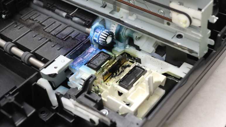
I pushed the print head carriage out of the way for a closer look at what lies beneath. There’s a lot of ink stain from years of service. It’s pretty clear the black cartridge lives on the right and the color cartridge on the left. For the color cartridge, it looks like the blue ink comes out of the left side and the yellow ink comes out the right. Curiously, I don’t see much in the way of red ink (or more likely magenta) even though I would have thought red would leave the brightest stains.
The front-most white gear, heavily stained blue, is attached to one of two paper feed roller shafts. I can see it meshes with gears further back, but I couldn’t see exactly what’s going on down there without further disassembly. The most intriguing feature that caught my attention are what looks like tubes. What flows through those tubes, where do they come from, and where do they go?
In the foreground of this picture, we see an assembly that sits below the print head when it is parked. The assembly can move at least vertically, possibly horizontally as well. The topmost features are two rubber squeegees, one heavily stained blue and another stained black but not as heavily. Next to those squeegees are what I assume to be ink absorbent pads. All appear to be useful tools to maintain, clean, and unclog ink nozzles.
For comparison, here’s a picture I took of the counterpart in a brand new Canon Pixma MG3620 before printing anything. I see many similar looking components, with the obvious difference of being factory fresh with clear squeegees and unstained white plastic.
Back to the MX340, I examined the print head carriage data cable and found it’s actually three flex cables stacked together. I had thought such stacking invited electrical interference between cables, but apparently not a problem here.
Tracing the cable back towards the main control board, there seems to be a pit stop at a small circuit board.
It turns out to be only a mechanical clip to keep the cable in place, there is no electrical connection to the little circuit board. The little circuit board has its own four conductor cable, visibly gray in this picture. The board houses another photo interrupter sensor for something in the gear box beneath it. I can’t see the rest of the gearbox, though, without further disassembly that carries a risk of breaking something. Since I want to poke around the printer in a still-working state, I am going to postpone gearbox investigation until later. I have enough other interesting things to look at.
A flatbed scanner is part of a Canon Pixma MX340 multi-function inkjet, and I’ve freed it from its associated hinges and damper. Once freed it was relatively straightforward to remove all visible fasteners and work around the perimeter to pop loose all remaining clips. I lifted the glass top and found it surprisingly empty inside.
During normal operation I could see the scanning head and two ribbon cables through the glass. I had expected to find more components hidden along the sides out of sight. At least a switch or sensor for the scanning head to find its home position. But there’s nothing, just structural ribbing and empty space.
One ribbon cable led to an assembly with visible gears, so it’s probably the motion control cable.
There weren’t anything else holding the scanning head in place, so I could flip it over to confirm four wires consistent with a stepper motor. The curious part is I counted five conductors in the long white ribbon cable. Either I miscounted or there’s an extra wire I lost track of, for purpose I have yet to determine.
I count twelve conductors inside the other ribbon cable, leading to one end of the scanning head assembly. I guess image data comes across this wire. While the ribbon cable and its associated connector are too small for me to work with, I see at least five through-hole pins on a circuit board and I could work with that. It’s something to look into more detail later.
The other end of the scanning head has a spring to help keep the imaging hardware tight against the bottom of the glass surface.
Speaking of which, I was surprised to find two separate pieces of glass. One for the large whole-page scanning window, and a separate narrower piece works with the automatic document feeder. I had expected a single piece of glass spanning across those windows. Why did Canon engineers decide two separate pieces were better than a single piece? There must be a good reason for increasing parts count and assembly complexity. Do these two pieces have different optical characteristics? Or maybe it’s a supply chain volume thing. The large piece would be a high-volume piece usable on all printers and scanners, whereas the small window glass is lower volume only applicable to machines equipped with an automatic document feeder.
The glass pieces were about 3.45mm thick, far thicker than I had thought they were. I guess I got too used to LCD glass that are less than a millimeter thick and easily cracked. I’ve always been scared to accidentally crack the glass on a scanner bed, thinking they were just as thin and fragile as display glass. Now I know better. They’re still glass so I should still treat them with care, but I won’t be afraid to breathe on them anymore. Another feature I appreciated is that their corners have been beveled so I’m less likely to cut myself open on these edges.
Seeing how robust they are, I’m inclined to remove these pieces of glass for reuse elsewhere. They seem to be held in place by double-sided tape. Peeling off the tape and cleaning any remaining residue should be trivial for a glass surface.
While looking over the glass, I noticed this distinct pattern of three black stripes on a white background hiding underneath the bar between the two visible scanning windows. I think this explains the lack of a physical homing switch. Rather than adding hardware for a homing switch, the imaging sensor (which needs to be on a scanner anyway) is used to look for this pattern indicating home position. I wonder if I can spoof it by printing this pattern on a sheet of paper? That’s a potential experiment for later. Right now, because I wanted to keep the entire machine functional, I had to put the scanning module back together. That’s the easiest way to keep this stripe in place and visible to the scanning head while I go off and play with the rest of the device.
I’m admiring all of the clever mechanical design as I take apart a Canon Pixma MX340 multi-function inkjet, even if some of the designs were too clever for me to figure out. Fortunately some of the mechanisms are more easily understood, like the damper mechanism.
After removing the top layer housing the ADF and control panel, the next layer is home to the scanner module.
This scanning bed tilts up for access to the ink cartridges.
A spring-loaded piece of blue plastic on the right props up the scanning bed assembly (and the ADF + control panel assembly above it) while we replace ink cartridges. When the task is complete, it is tempting to retract the blue plastic support and let the top slam shut. But slamming shut would destroy fragile components like scan bed glass.
Which is why Canon engineers have incorporated a damping mechanism to make sure the lid closes gently. This mechanism is my next teardown target. I could see most of it after removing side panels from the base.
Leaving only a small clipped-in cover before the entire mechanism became accessible.
Six removed screws later, the whole damper mechanism was free. It was a lot simpler than I had expected. The black arc is rigidly attached to the scanner, with geared teeth to engage with the upper white gear. The lower white gear is where the damping happens.
Here’s a closer look at the gearbox still installed. Two small black assemblies surround the lower gear, it felt like they contain a viscous fluid to accomplish their rotational damping. I might want to reuse them later, so I didn’t take them apart. Which also avoided making a mess.
The upper gear is not fixed at a single location, it is allowed to move almost 1cm in a slot, with a piece of spring to hold it against the upper side of the slot. When the user lifts the scanner for a ink cartridge replacement, the upper gear follows along and moves to the higher position. This movement disengages the upper gear from the lower gear, so the lifting motion is not damped. But when the lid starts falling, the upper gear is pushed to the lower side of the slot, engaging the lower gear and its pair of little black dampers.
This meant the user can lift the lid as fast as they like and not have to fight the damper before they could access the ink cartridges. After they were done, they can let go of the lid and the dampers will automatically engage to slow the fall. I had expected something more complex was necessary to implement unidirectional damping, but it was just a movable gear held by a piece of spring. Cool.
Once the damper was removed, I looked at the hinge itself and it’s a simple plastic nub in a slot. Bending a little plastic was enough to free the hinge.
Once they were both freed, I could access all of the fasteners holding the scanner module together, allowing me to take that apart and look inside.
It was fun to look over the automatic document feeder (ADF) in this Canon Pixma MX340 multifunction inkjet. Thanks to clever mechanical design, it only needed two sensors and a single motor to feed a stack of paper through the scanner one sheet at a time. After removing those components I was faced with the hinge mechanism holding the ADF (and control panel) up above the scanner bed.
In addition to normal hinge rotation, these hinge modules can move vertically extending upwards by about 3cm. This accommodates thicker material on the scanner bed, such as a book. Some kind of a mechanical stop prevents them from being pulled out more than that 3cm. Not falling apart during normal use is great, but now that stop mechanism is an obstacle blocking progress in my teardown.
After removing the control panel and ADF, I have a large tray and two hinge modules, each held by three fasteners.
Removing the fasteners freed the module from the tray. And while that gives a bit of play moving the module around, the top part is physically too large to fit through the tray slot. The hinge module has to be removed from the scanner bed below, but I couldn’t see what’s still holding it place because the tray is still in the way. The teardown so far tells me Canon engineers must have designed for graceful and non-destructive removal, but my belief didn’t lead to useful insight. Fingertip tactile feedback tells me there’s some sort of mechanical interaction down there, but I couldn’t see it to understand what I’m feeling.
Conceding defeat, I went with the brute-force mechanism and pried one hinge assembly loose. This damaged its vertical channel. Once removed, I could see how things worked: a small tab held the hinge module in a vertical channel. This channel is blocked on top to keep the hinge from falling out during normal use.
As long as the tab stayed in the channel, the hinge module stayed inside. However, there was a small slot in the side of the channel around halfway up. To remove this hinge module non-destructively, we have to slide it sideways into that alternate channel.
This sideways movement was not allowed until the three fasteners holding the hinge mechanism to the tray were removed. But given that little bit of mechanical play, we can move the tab into the alternate channel. It is not blocked at the top, allowing the hinge module to slide out. Those Canon mechanical engineers were sure clever, too clever for me to figure out their trickery on this first pass. Maybe I’ll encounter a similar mechanism in the future, but it won’t be in this teardown. The next hinge down is for the scanner bed module, and it’s completely different.
I disassembled the control panel for this Canon Pixma MX340 multi-function inkjet and took a quick look from a mechanical perspective. I’ll return later for an electronics examination but right now I wanted to dig into the rest of the scanning/copying automatic document feeder (ADF). I got a taste of what’s involved in an ADF from a clever lid mechanism, now it’s time to see the rest of it.
The control panel had to be disassembled first because it uncovered the fasteners and latches I needed to release before I could remove this back cover.
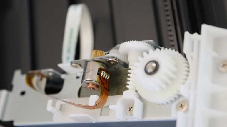
Then I could see the ADF motor and gearbox assembly, including the gear that drove the ADF lid paper feed rollers. Judging by the presence of four wires going into this motor, I believe this is a bipolar stepper motor.
Removing the bottom of the ADF paper feed tray allowed visibility into the core of this mechanism. In addition to paper handling rollers, I see a pair of photo interrupter sensors.
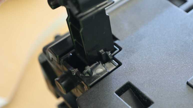
A plastic paddle attached to the bottom of the ADF paper feed tray slots into a sensor, visible towards the top of this picture. It detects when a document has been placed in the ADF. The sensor at the bottom of this picture still has its matching paddle in the slot, it detects whether a sheet of paper has been properly fed into the roller assembly.
Adjacent to the motor gearbox, I saw a beefy ground wire attached to foil tape.
This foil tape led into the middle of the ADF assembly…
… and out the bottom where it hovered over the entire width of the output tray. I believe this intends to dissipate any static electricity built up after the sheet of paper passes through the document scanner. The more interesting question is: was this always part of the design? Or was this added after testing uncovered problems with static electricity buildup? Foil tape is simple and effective for conducting low current, a good fit for managing static electricity buildup. But if static electric dissipation was the goal, I would have expected some stamped sheet metal integrated into this plastic structure. Foil tape felt like it might have been a hack. Which is fine, if it was. Canon engineers are only human after all and this machine already has more than enough intricate designs to facinate me.
This inkjet teardown is off to a great start, with an interesting mechanism to feed the top sheet of document into the automatic document feeder (ADF) without requiring its own motors or wiring.
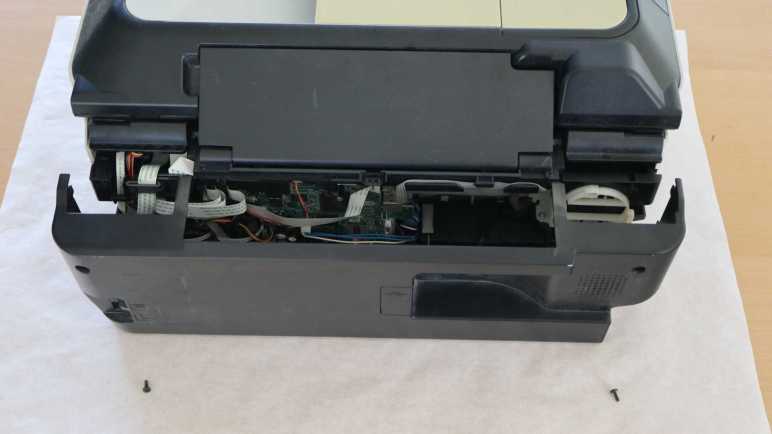
The next assembly I managed to free was the control panel.
I failed to find visible fasteners, but there were a few of these rectangular slots with arrows that I have learned was Canon engineer’s way of indicating “Here’s a plastic clip you can unlatch.”
Unlatching a trio of them allowed me to slide out the white plastic trim underneath the control panel, exposing many other plastic clips and fasteners.
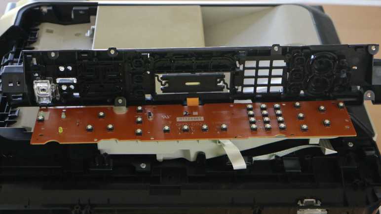
Which allowed removal of the control panel facade, exposing… another layer of plastic! The top layer is focused on appearance, this next layer handles mechanical functionality for all the buttons.
I had hoped the LCD module is in its own little standalone sub-assembly, because that would be the easiest for me to repurpose elsewhere. Sadly that doesn’t look to be very likely here, as the screen is bonded to a segment of flex PCB with very fine pitched wires.
Flipping the control panel module over, I confirmed LCD connector is a tiny thing. The only other connector is for a white ribbon cable leading to the main board at the back of the printer. I see a single large IC on this board. The combination of LCD + buttons + single chip remind me of the control panel from a Toyota factory tape deck. There’s a chance this printer control panel is designed along a similar architecture. Maybe that single IC is in charge of scanning through and refreshing LCD segments as well as scanning the array of buttons?
Removing all the visible fasteners allowed the plastic button mechanical layer to be separated from the electronic circuit board, where I could confirm this is a single-layer board. Right now I want to stay focused on mechanical disassembly, proceeding to disassemble the automatic document feeder. I will return to this circuit board board later to investigate its electrical properties.
I started taking apart this Canon Pixma MX340 multi-function inkjet from the back panel, but I didn’t get very far before I got stuck. Next I’ll try another angle, starting from the top. This device has an automatic document feeder (ADF) up top to help scan/fax multi-page documents.
In case of paper jam, this ADF lid flips open to help us clear them. A few fasteners were visible with the lid open, but removing them were not immediately helpful for disassembly. This piece of plastic must be held in place by other things. Two spring-loaded latches on either side of the lid keeps it in place when closed. These latches were interesting because they had to be loose enough to make the lid easy to open, but tight enough to keep the lid in place while the feeder is running. Note the white gear visible towards the top right of this picture, more on that later.
The lid itself were not held by any fasteners at all. Bending a few pieces of plastic were enough to free it from its hinge. This caught my attention because I saw multiple paper feed rollers on this lid, but there were no cables in this hinge.
Power is transmitted to rollers via that gear on the lid’s back edge. Turning this single gear activated multiple functions. I can see the dual-roller mechanism flip out from the lid, which would put some pressure on the top sheet of paper in the document feeder. Once this pressure was applied, continuing to turn the gear would start turning rollers to help feed that top sheet into the feeder.
If I were to design a mechanism to do this before seeing Canon’s solution, I would have used a servo to put pressure on the roller and a separate motor to turn the roller, two motors — and associated complexity and potential failure points — instead of this clever mechanism. This is why I am not working as a mechanical engineer for Canon.
The topmost white plastic piece in this lid were held by a few clips. Once removed, we can see internals of the spring-loaded latches and the roller mechanism.
Friction plays a big part here. The paper feed roller themselves are covered in soft rubber for traction, and that rubber layer has dried and cracked with age. The roller pressure mechanism also works with friction to some degree, tight enough to rotate this mechanism to put pressure on the top sheet of paper but loose enough to allow the rotation force to gracefully transition to turning the paper feed rollers. I expect this friction mechanism to wear down with age, putting less and less pressure on the top document sheet. It’s not great to have a mechanism designed to gradually destroy itself, but the fact is, it lasted to retirement. It’s not just good, it’s good enough!
I enjoyed looking over this unexpectedly complex mechanism, and I’ve barely started taking the inkjet apart. I hope there are more fascinating details as I continued this teardown.
I’m taking apart this Canon Pixma MX340 carefully, hoping to keep all of its system in a running state so I can learn more about how it works. Lucky for me, Canon engineered this machine with disassembly in mind. I’m not sure of their original motivation to do so, but it was an appreciated surprise. Given the nearly disposable nature of printers in the inkjet economy I had half expected something glued together.
I started looking for ways to get into the printer from the bottom, where the product label lived.
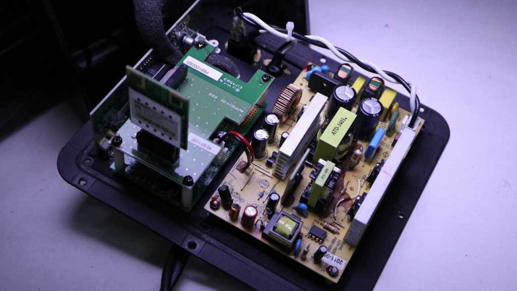
Also accessible from the bottom is the AC to DC conversion power supply. Held in place by a single plastic tab marked in this picture with a red oval. Given this unit is listed to accept 100V AC and output 24V DC, I assume a different unit is used for sale in countries with 240V AC. The AC input side uses an IEC 60320 C7/C8 “figure 8” connector and the output side has three wires (white, blue, blue) just visible to the left in this picture.
I found no exposed fasteners on the bottom. I found two exposed fasteners in the back, and removing them freed the rear panel.
Behind the rear panel is a circuit board, looking like the brains of this whole operation. Roughly a dozen connectors carry power to and data from the rest of this printer. As this teardown proceeds I should get an idea of the purpose for each of these connectors. I can start with the white-blue-blue wire just below the center: that receives power from the power supply and it makes sense majority of capacitors are clustered around that area.
Above the circuit board, I can see there are no fasteners or clips holding the paper feed tray in place. It can be removed by bending the plastic away from plastic nubs acting as hinges.
Removing the rear panel also exposed this fastener for a side panel.
The same panel has a fastener on the front, accessible by lifting the scanner module.
After removing those two fasteners, I yanked on the panel and it came free but not without damage. There are two long clips in the middle of this panel. The rear clip survived but I broke the front clip.
In hindsight, I see that Canon engineers had placed hints on how to release these clips without damage. Small rectangular holes were cut into the surface, with small triangular arrows drawing attention to them. I noticed the arrows earlier but I didn’t know what they meant! Now I understand this symbol and shape mark locations to access clips for removal. And once I knew what they meant and knew what to look for, I see them all over this printer. Thank you, Canon engineers!
Now that I have this knowledge, I could remove the other side panel without damage. Unfortunately I could make no further progress taking apart the base at the moment. I have found more fasteners, but they are blocked by the hinged scanner module above. My next step will disassemble the automatic document feeder at the top and work my way down to the base.
I have a stack of retired inkjet printers on my teardown waiting list, supplied by an industry whose ink cartridge-focused business plans render printers borderline disposable. I’ve learned a lot about electronics and mechanical engineering since my last inkjet teardown, so I’m going to do another one and I hope to get more out of it. Both in terms of knowledge and salvaging parts for potential reuse.
This Canon Pixma MX340 will be the next to receive the teardown treatment. I bought this around 2011 when I needed a fax machine and a scanner that can go directly to PDF on a flash drive. The automatic document feeder (ADF) on top of the machine made life easier when I needed to fax or scan a multi-page document.
Flipping open the lid for the ADF document feed tray, I can see sunlight over these years has yellowed exposed exterior trim. This all used to be the same color!
This machine is built with multiple hinged layers. Top layer housed the control panel and ADF. Lifting that exposes the flatbed scanner bed. Useful for items that aren’t suitable for the ADF, such as books or items with fragile/wrinkled paper.
Lifting the scanner bed exposes the print mechanism. Nowadays I have a monochrome laser printer that handles most of my printing needs, because I rarely need to print in color. The last time I wanted a color print, I fired up this MX340 only to find the neglected nozzles have clogged. The unclog procedure didn’t fix the problem, so I started thinking about replacement cartridges. I still have a 210XL black cartridge unopened in original packaging. No 211 color cartridge, though, and I only found a few places that would sell Canon 211XL cartridges. Asking price is about $35 which is discouraging when new color inkjet printers can be found on sale for about $40. The ink cartridge that comes in a new printer won’t be the higher capacity “XL” variety, but I don’t need a lot of color printing. In my usage pattern the cartridges tend to dry out and clog before I use up all of their ink.
This specific printer is so old even the aftermarket cartridge vendors don’t bother carrying a compatible cartridge. Canon has discontinued support for this hardware, so it will never receive printer drivers for Windows 11 or Apple Silicon MacOS. Its WiFi connectivity is built around WPS, which is now considered insecure and not even supported by my WiFi router anymore. All of these reasons added together lead to the decision to retire this printer. I’ll buy one of those $40 printers when I need to print in color again.
I opened my 210XL black cartridge and installed it in the printer, then tried an ADF copier test run. The dried-out/clogged color cartridge did nothing, but thankfully this printer was willing to print anyway. (Some of the more annoying printers will refuse to run with an empty cartridge.) The test run verified all mechanical components in the automatic document feeder, scanner, and inkjet printing engine are in working order.
Since the components are still working, my teardown plan will include a stage where I poke and prod a disassembled (but still running) device. I hope it will be educational.
Phase 1: Take this printer apart as far as I can while still preserving electrical and mechanical functionality.
Phase 2: Bring out the multimeter, oscilloscope, and logic analyzer. Measure motor & sensor electrical behavior and write them down. Learn what I can about how they work. Such knowledge improve the odds I can reuse them later.
Phase 3: After I have learned all I can, take it apart the rest of the way.
Endgame: Keep salvaged components with reuse possibilities. Recycle the metal bits, circuit boards goes to e-waste, and plastic goes to landfill.
I thought a malfunctioning hair trimmer was a simple device and I understood why it failed. But it turned out to be more complex, my deduction turned out to be wrong, and I had no further ideas. Giving up on it didn’t feel great, but I did learn a few things. A few salvaged parts may yet see reuse in a future project, and the components were separated. The metal parts could be recycled, the circuit board is going to e-waste, leaving only the plastic bits to landfill. This is roughly the same situation as the last time I took apart a retired inkjet printer.
Inkjet printers were a wonderful invention enabling affordable color printing. Unfortunately, the product ecosystem have landed on a wasteful business model deriving profit from ink cartridge sales. Printers were built to be sold cheaply, other concerns like long-term durability became secondary. Short warranty periods and discontinued printers became the norm. Speaking for myself, I rarely need to print in color. When I do, I tend to find my cartridge had clogged up along with other problems caused by lack of use. Like paper jams caused by rubber rollers that had hardened and no longer had good grip on paper. Considering the fact a cartridge for an old discontinued printer cost almost as much as a new printer, it’s easier to just buy a new printer. Sure, the ink cartridge bundled with a new printer has less ink, but it is likely to clog from neglect before I actually run out either way. And thus the cycle repeats.
A small upside to this sorry state of affairs is that teardown tinkerers have a steady feed stock of retired inkjet printers. I let friends and family know I’m interested in their old inkjet printers as well, and they’ve been happy to let their broken printers gather dust at my house instead of theirs.
Years ago (before I started writing down projects on this blog) I took apart a few of those printers. I was fascinated by the amount of engineering that went into even entry-level printers. But I was frustrated by the fact I didn’t understand very much of what went on, and couldn’t put the components to other use. At least the metal parts got recycled and I kept the circuit boards out of landfill.
But I’ve learned a lot since my last inkjet teardown. I managed to put one power supply to use (multiple times, actually) and I’ve learned things like driving stepper motors I pulled from those printers. I have an oscilloscope and a logic analyzer now, and I have 3D printing to help reuse the mechanical bits. I still won’t understand everything inside an inkjet printer, but I will understand more than before, and that’s good enough to embark on another run.
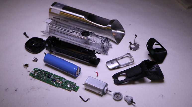
Joining a dead-again subwoofer on my failed repair hall of shame is my Philips Norelco Multigroom MG7790. It had been halting partway through a haircut session, stopping the motor and pulsing its amber LED. My first guess was a failing battery, but the battery looked OK. I then thought the problem was a clogged cutting blade module. I cleaned it up and it tested fine through one session, but then it died again on a second session with a still-clean cutting blade module. I had misdiagnosed the failure a second time and again out of ideas.
Taking it apart, I confirmed battery voltage was not the issue, measuring at 4.08V. I could spin the motor freely by hand, so it’s not a stalled motor. I know the button works, because pressing it would start the amber LED pulsing instead of the motor turning as expected. So… what’s left? There’s not a whole lot to this device!
Examining the circuit board, I didn’t see any obviously damaged components. And there were quite a few of them, more than I had originally expected from a device that turns a motor on and off.
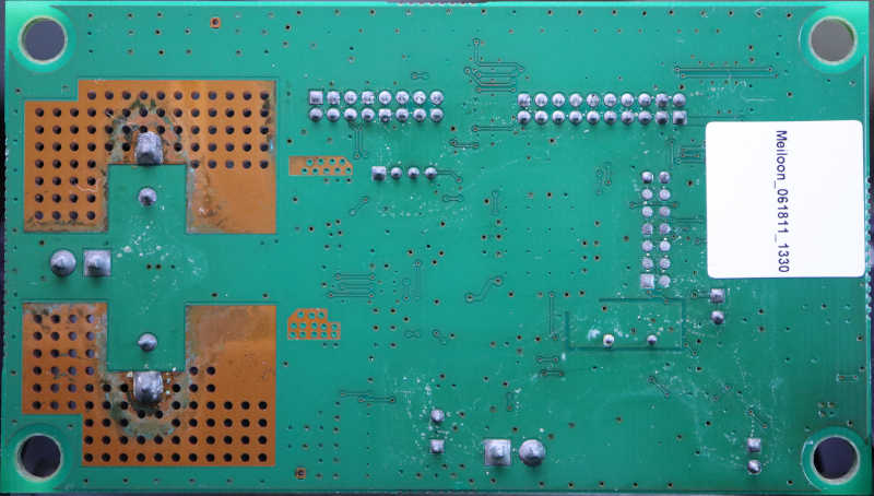
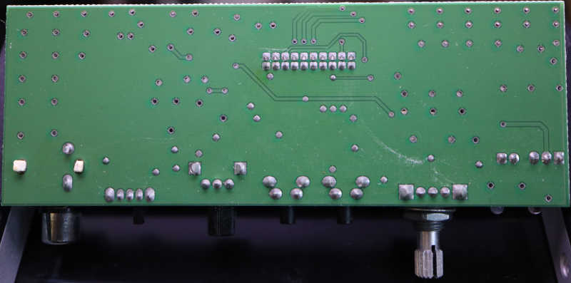
Here’s the back side of the circuit board, completely empty. Seeing it was a single-layer design, I briefly hoped I could try to understand how this circuit works, but I didn’t get very far.
The good news is that, as a single-layer board, I could light it from behind to get clear look at most of the traces. I haven’t built any kind of lighting setup for this, so it’s still just my cell phone’s LED flashlight same as my quick side-light experiment. Here’s a crude mosaic of several different shots, taken with the LED behind different parts of the circuit board. One thing is clear: there are a lot of test points on this board.
The bad news is I have no idea what most of these components are. Some of them are labeled like resistors, but some others are engraved with only a few difficult-to-search characters, only slightly better than the remaining components which have no markings at all.
And everything is just so tiny. For a sense of scale, here’s a 1:1 pixel crop of the lower left corner of the previous picture. This was a well-used hair trimmer, and my teardown is plagued with little bits of hair getting everywhere. That small black cylinder in the middle of this closeup is one such hair fragment, conveniently providing a sense of scale of these components. These tiny parts are beyond the reach of my current skill level.
While somewhat frustrating, I have to be OK with not understanding everything as I play with retired electronics. Especially since I don’t have any of the technical documentation proprietary to the company. In keeping with this mindset, I’m going to take apart a few inkjet printers.
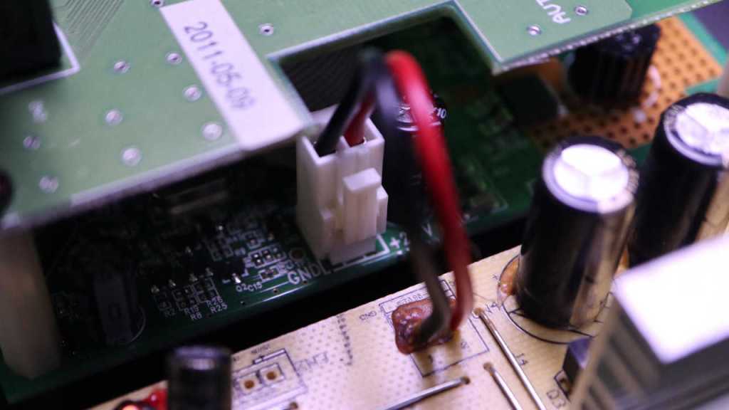
About a year ago I opened up my malfunctioning Insignia 100W Powered Subwoofer (NS-RSW211). I found a burnt-out capacitor, and replaced it with two salvaged capacitors that should work well together. That repair brought the subwoofer back up and running until it fell silent again recently. I looked at the control panel and saw the power LED was dark. Hmm. Back onto the workbench it goes for another round.
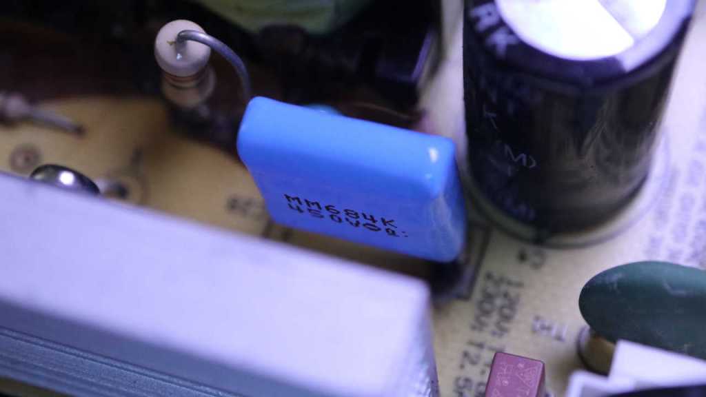
The first thing I checked out were the capacitors I previously installed. If there was a flaw in this system that kills capacitors, it might have killed this second set.
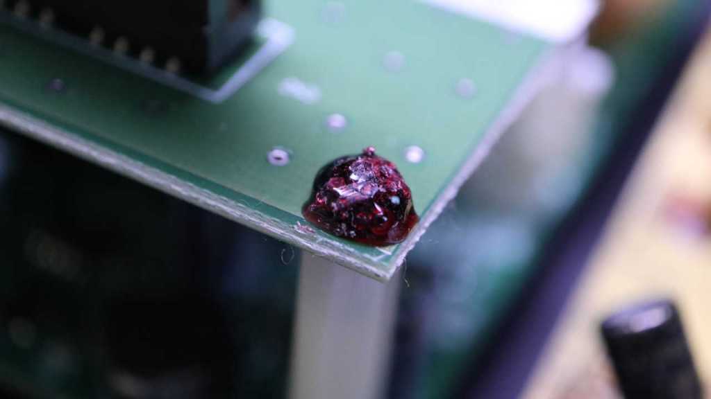
The capacitor up top looks fine
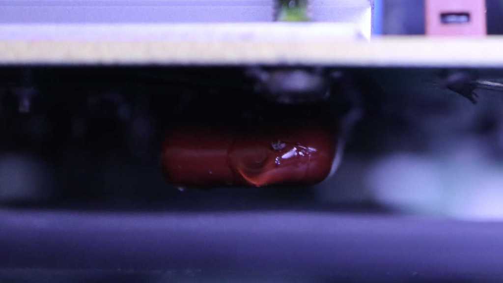
As did its parallel buddy mounted to the bottom. I don’t know if their capacitance has degraded and I don’t feel like unsoldering them to check. For now it is good enough they are not blackened like the original when I found it.
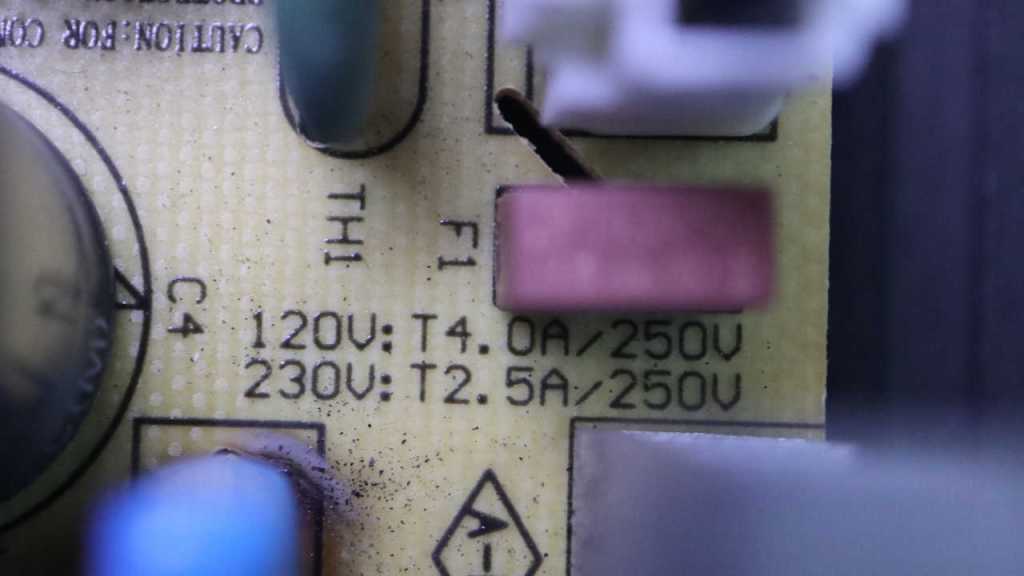
The next thing I checked was the non-user-replaceable fuse sitting adjacent to these capacitors. Electrical continuity checked out OK so it’s not a blown fuse.
Trying to isolate whether the fault was again in the yellow power supply board, I powered up the system and measured its output connector to the logic board. I read 24V DC, exactly as expected. Implying the fault was not in the power supply board. Onward to the logic boards!
Its top screws had this annoying material on top. I don’t know if this is supposed to be a thread locking compound to keep it from coming loose (a good idea in the vibration environment of a subwoofer) or if it’s supposed to be tamper-resistant. It wasn’t much of a barrier, though, as it is brittle and shatters under light pressure for removal. Maybe it’s meant to be tamper-evident?
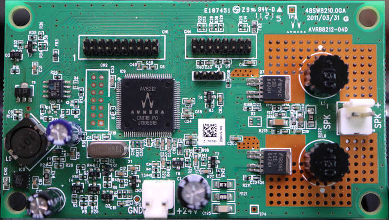
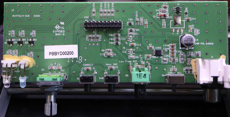
I didn’t notice anything burnt out or visibly damaged on the main logic board, which had an Avnera logo in the upper-right corner as well on the AV8212 controller in the middle the board. Apparently Avnera was the subcontractor for this Insignia (Best Buy house brand) product. Avnera was acquired by Skyworks in 2018 and now every link I’ve found just gets forwarded to the Skyworks home page. Dead end.
Nothing obviously failed on the I/O board, either. I was surprised to find the volume knob appeared to be a quadrature encoder instead of a potentiometer. From this I inferred the volume could be adjusted via the wireless protocol supported by this device. Something I’ve never used so I never noticed.
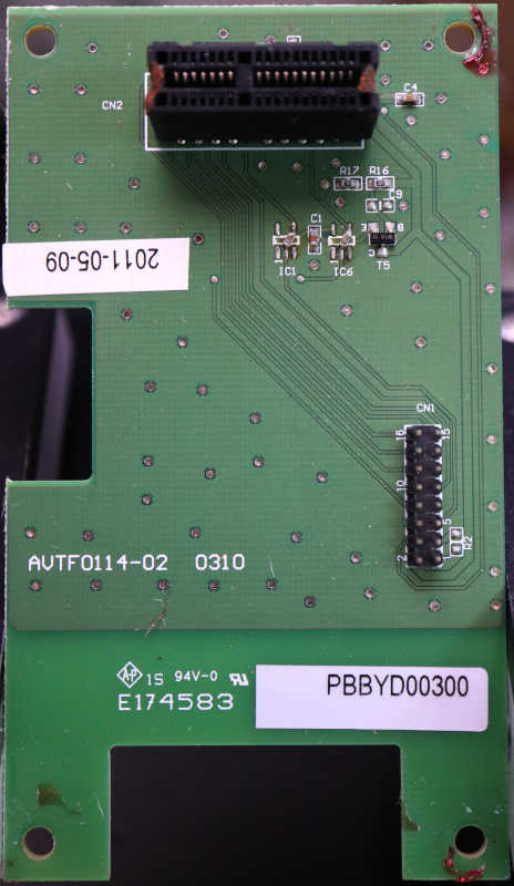
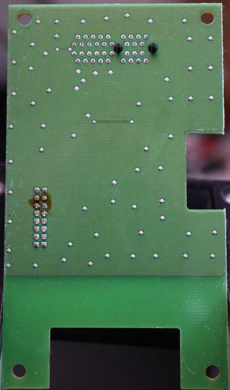
Nothing obviously failed on the wireless carrier board, but then again there’s not much on this board at all. The 16-pin connector is for a ribbon cable to the mainboard, and it is routed almost directly to a connector for the wireless module. It looks like a PCI Express x1 card slot.
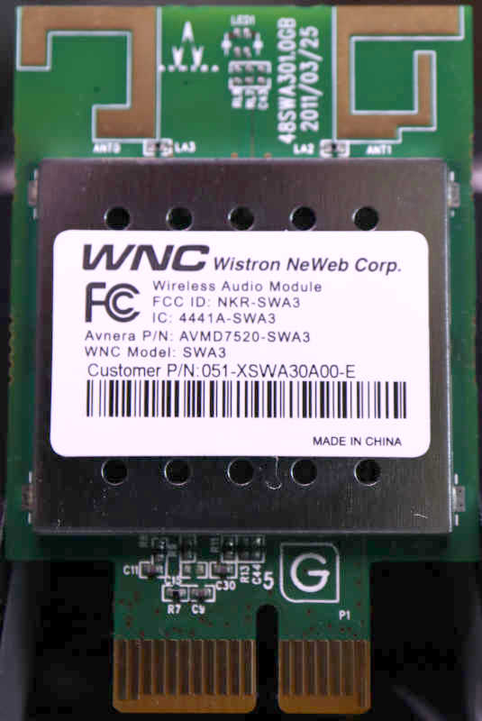
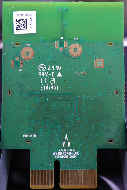
And finally, the wireless module itself. No obvious signs of failure here but most of it is under that metal shield. I see the Avnera logo front and back on the circuit board, but the stick had a different name: Wistron NeWeb Corp. This company has not been acquired by Skyworks, but there were no results for a query on model number SWA3. There’s an Avnera part number AVMD7520-SWA3 but I’ve already established Avnera’s website is gone. That left the FCC ID NKR-SWA3 and that returned some interesting results from FCC’s database. One bit of trivia: they did, in fact, use the PCI Express x1 connector but this is not a PCI Express card.
Sadly I didn’t find any signs of a failure I could fix. Since the 24VDC power supply seems to still be good and the speaker driver itself looks OK, I went online looking for subwoofer amplifier modules. The DC-powered units I found were designed for cars expecting 12V-14.4V and not all the way up to 24V. And regardless of AC or DC power input, everything I found were aimed at powering big booming boxes. Not basic units like this one, so they tend to cost more than just buying another basic little sub. I admit defeat and conclude I’m at the end of the road for this device. Since I had most of the components taken apart already, I continued taking things apart for curiosity’s sake.
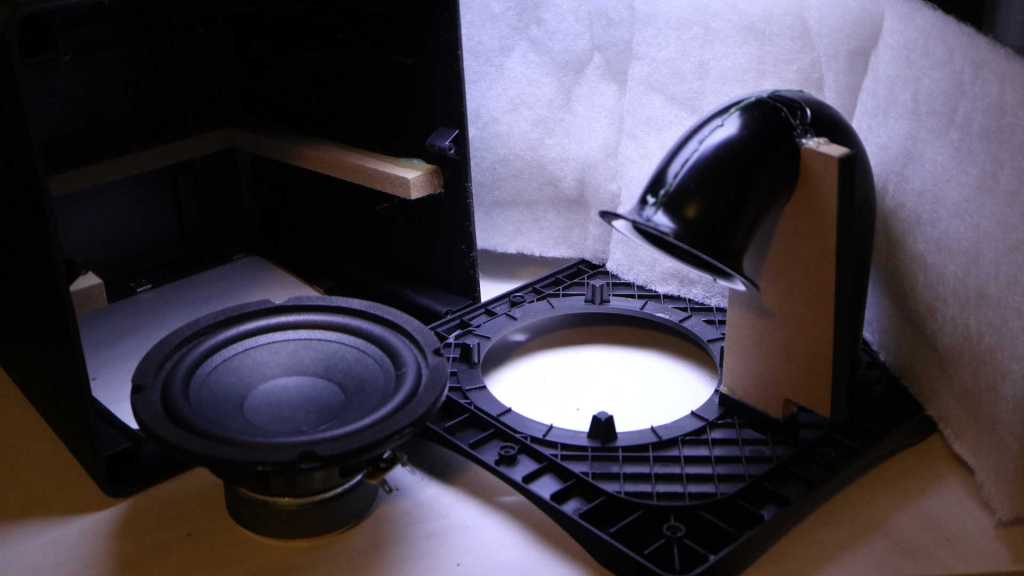
Beyond the electronics box, the cabinet was mostly a big box to surround the speaker driver and padded with white fluffy batting.
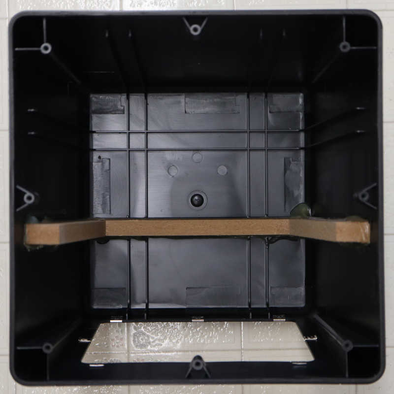
The air duct and port design is interesting, allowing air movement in and out of the subwoofer enclosure. I recognized flared edges exist to reduce hissing airflow noise, but I don’t know the art/science behind the length and shape of the tube. I just think it looks neat! [UPDATE: Thanks to a comment by Nic, I now know this speaker is a bass reflex system and science behind the tube is based on Helmholtz resonance.] Too bad it is glued in place. I’m curious about the few pieces of MDF supporting the injection-molded plastic. What are the respective strengths and weaknesses of these two materials? I thought there was a chance the MDF were late additions to the design to address problems, but they look too well integrated for that. There’s a slot molded in the plastic for the MDF piece supporting the duct.
As for the outer enclosure, it looked like multiple slots were molded in place but only one was occupied by a piece of MDF. Perhaps they were reinforcement ribs instead of MDF slots? I can sense some sort of design intent here but I have no guesses on what they were.
On the left, both switches are in their “On” position, and this is fine. On the right, top switch is in the proper “Off” position, but the lower switch could not do the same. If I flip the lever to “Off”, it doesn’t stay there but would move back a bit. Sometimes that’s still electrically off, which is fine. Sometimes it springs back to electrically on and I have to try again, which is annoying. But the real problem is the rare case when it stops in an unfortunate middle ground, and I can hear a lot of popping noises consistent with sparks/arcing inside the switch. Very bad! I replaced it promptly to avoid risk of permanent electrical damage. After it was replaced, I want to see exactly how the switch mechanism failed.
On the back side of this unit is a rivet-like structure, surrounded by text PAT PEND (patent pending?) and SPEC GRADE. I have no idea what spec it met the grade for, but I know this rivet has to go.
After drilling it out, its front facade was still held by four plastic clips. When I pried that face open, it was a sudden release and everything flew apart. Several pieces of metal landed at various places on my workbench. I think I found them all, but where did they used to live, and what were their function?
Two large pieces remained inside. They look like they carried power, with a rounded contact pad at the end. Two of the metal pieces that fell out have matching contact pads and wiring screw terminals, they must make up the rest of the power-carrying circuit. The lower pads are more charred-looking than the top, consistent with suffering a few arcing episodes, but other than that both sets look identical and would not explain the problem.
My hint came from looking at the lever’s back side. There are actually two levers sticking out. The shorter wider portion pushed on the large electrical bar, and the longer narrower portion pushed on something else. Process of elimination says it must be the two remaining pieces of metal that fell out.
Those narrow pieces of metal must have mounted to the side of the enclosure on their flat ends and acted as springs that held the lever in one position or another. When holding their flat ends together on the tabletop, one of them is visibly more tired. The weaker spring could no longer hold the switch lever in the off position.
So the switch was electrically fine, it was just a worn out lever spring. Would it have resumed working if I could manually bend the spring back and reassemble the switch? Maybe, but this double-switch was not designed to be repaired. After I drilled out the center rivet there was no secure way to put it back together safely enough for use.
It’s fine, it served its purpose over many years. And amusing enough, its replacement served one final purpose: letting me know my UPS batteries are no good and I need to buy replacements.
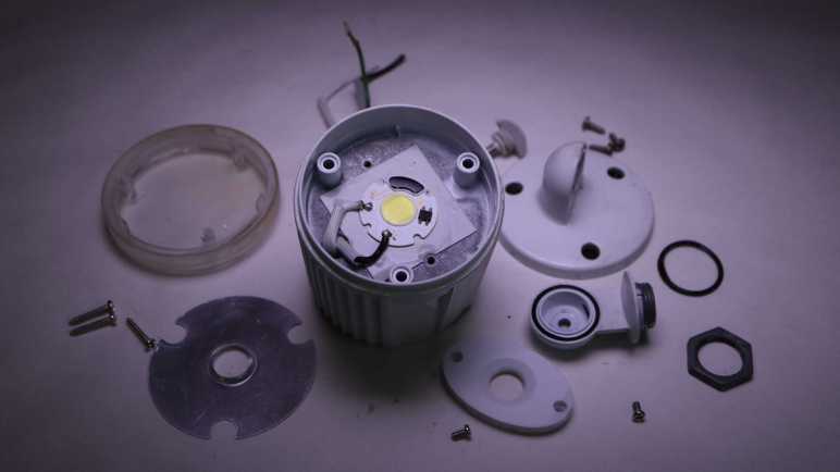
I am taking apart an Aurum motion sensing light fixture because its sensor and control circuitry has been damaged by water and no longer performs correctly. The pair of lighting modules still light up on command, though, so I’m hopeful I can find another use for them elsewhere. Let’s see what’s inside.
Based on my understanding of the sensor circuit, each of these two pods are capable of functioning as standalone 120V AC lights. White wire for neutral, black wire for live, and green wire for ground.
Supplying power lights up this little yellow circle of bright white LEDs, roughly one centimeter in diameter. It’s such a small surface area for a bright light source, especially relative to the volume of the rest of this pod. What is all that volume used for?
Like the sensor pod, a single fastener holds the elbow joint together and is easily disassembled.
Next is a trio of fasteners, easy enough to remove to let us see what’s inside the cylinder.
The answer: mostly air.
I had expected to see some AC to DC power conversion circuitry and was surprised to see such emptiness. The ground wire screws to the metal enclosure, but the live and neutral wires kept going to the front of the pod. There’s nothing else except access to three more screws.
Loosening those three screws released the front of the pod.
The plastic front was originally clear, but now yellowed and clouded with age. Moving it out of the way gives us a clear look at the LED array.
Cranking my lens to “Super Macro” mode enabled this picture, showing an array of 6 * 7 = 42 LEDs all wired in series. That would require north of 120V DC to drive, a pretty close match for rectified 120V AC. But I haven’t seen that rectifier yet.
Removing the oval plastic cover revealed this LED module in COB (chip on board) form factor. Made by Paragon LED, this compact circuit board accepts 120V AC power directly on its pads labeled L (line) and N (neutral). From there it takes care of everything else necessary to convert that power to light.
The second-biggest module (after the LED array itself) is this BT10S rectifier from HY Electronics, converting 120V AC power to DC and sending it onward to the LED driver somewhere under a black blob.
The Paragon LED module is fastened to the metal can with a gray square of soft sticky material. This must be a thermally conductive adhesive pad. And thus I have my answer to why we need a big metal can to support less than one square centimeter of LED: the COB needs a hefty heat sink.
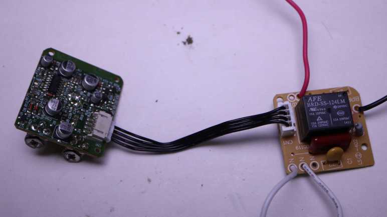
At a high level, it looks like one board handles the 120V AC power with a relay and the other board handles sensing and sensor logic. Four wires connect between them.
Looking at the front of the power board, the black wire is incoming 120V AC line, red wire goes out to light pods. The two white wires, one incoming and one outgoing, are 120V AC neutral. This confirms the sensor pod only switches AC power. Converting AC power to DC voltage to drive LEDs are handled elsewhere inside the light pods. There are only a few components on this side, dominated by an AFE BRD-SS-124LM relay. Surrounding the relay are what appears to be a resistor, two capacitors, and a 4-position connector to the logic board.
Looking at the back of the power board, I can see both neutral wires are wired together. Looking at AFE Relay’s product information for BRD series footprint, I can see the relay will connect/disconnect between the black and red wire for 120V AC line power. This is the business end of the sensor pod and determines whether the light pods receive 120V AC power or not
Beyond that, I’m lost. I had expected to see a transformer to turn 120V AC into a lower voltage, followed by a rectifier to turn AC into DC suitable for a digital logic board. I definitely don’t see a transformer here, and I don’t see a rectifier module. These small red things labeled with D are probably diodes, do they implement a diode bridge? If there’s no voltage reduction, does it mean 120V go all the way to the sensor logic board? Maybe looking there would help me understand what’s going on.
Here’s the sensor logic board with the actual sensor itself front and center. U2 is a status LED. Potentiometer LUX SR1 adjusts level of light sensitivity, TIME SR2 adjusts how long the light should stay on after motion detection threshold has been triggered. The brown tint on the potentiometers are rust, result of rainwater intrusion. They would have been the closest components immediately below the broken sensor view window. Such exposure wouldn’t have done their electrical behavior any good.
In front of the sensor is a shiny bracket, dividing its field of view into thirds: left, front, and center. Here’s an oblique side view of the arrangement. I had hoped to read markings on this sensor so I could go look for a datasheet, but I saw nothing. Maybe it’s hidden by the shiny bracket? It might be plastic with a shiny coating, which I can cut away. If it is metal I doubt I could remove it without destroying the sensor module.
And now, the star attraction: the unexpectedly complex sensor logic board. It’s a single layer board, so I noticed multiple zero ohm resistors used as an overpass over other traces. Lots of other nonzero resistors, capacitors, and diodes. I see three components labeled BR 34 and two labeled FR 33, short enough of an alphanumeric designation a search returned a lot of hits but none I recognized as relevant. The silkscreen designation for those components start with Q. Wikipedia page Reference Designator says Q are transistors.
Since it’s a single layer board with few components on the opposite side, there’s no need for side light trickery. Shining a light from behind is enough to highlight majority of copper traces on this board.
One way I try to orient myself on the nature of a circuit board is to look for the big brain in charge of the operation. If I can find a datasheet for the microcontroller, there’s usually a section about the intended market for the device, the peripherals it has to support that market, and have sample application schematics. The biggest chip on this board has a ST Microelectronics logo and markings 324 GZ17334. A search led me to LM324 series of quad op-amps. Not a microcontroller, and I see no other obvious candidates for one.
The lack of a microcontroller combined with the largest chip containing a set of op-amps imply this circuit board runs on analog logic. A field I know even less about, and marks the end of the road of what I can decipher about this circuit board today. I set it aside to focus on the LED lighting pods this circuit board formerly controlled.
I retired a motion sensing light because water got in the motion sensor pod and it stopped sensing motion like it’s supposed to. Now I’m taking it apart. This post focuses on the motion-sensing sensor section.
I cleaned everything before the teardown, so sun damaged caused the discoloration visible here. We can really see where this sensor pod was shaded by adjacent light pods and where it gets hit with sunlight. The mounting thread is pristine, as it was safely shaded by the sheet metal base.
A single screw holds the elbow joint together and is easily removed for disassembly.
The wrist joint is a different story. I see no visible fasteners and, to make things more complicated, it blocks one of two screws holding the sensor pod together. I’ll look at other parts of the sensor pod and come back to this headache later.
There are two adjustment knobs on the bottom of the sensor pod. Looking through the damaged sensor window, I can see they’re connected to rusty potentiometers inside. No fasteners or retention mechanism visible from here, so I’ll try giving it a hard yank.
Brute force pulls them out after overcoming a retention clip mechanism I couldn’t see before. There’s also a small soft translucent rubber band to mitigate water intrusion.
One of the sensor pod screws came out easily, but the other one is still blocked by the wrist joint I couldn’t open. I have no good ideas on how to access that screw, but looking inside the sensor window I could see where the screw threads into. I could use my Wondercutter to cut that off at the base. It should be able to cut this plastic but it can’t cut metal, so I referenced the removed screw length to know where to cut in order to avoid the still-installed screw.
Once cut, the pod opened to reveal far more electronics than I had expected. I thought this was one of those products where component count is squeezed to an absolute minimum. So I expected to see a single circuit board with a half dozen components. There are actually two boards separated by a piece of clear plastic, connected by a 4-wire cable, and I estimate several dozen components across both boards.
Two rusty screws held the front board in place, two more held the rear board in place, before everything came apart.
Now that I can look at the wrist joint from the inside, I can see there was no elegant way to remove it. I would either have to pull on it hard enough to overcome these one-way clips, or cut something. I guess I had accidentally stumbled into the least-cutting way to open this sensor pod.
The inside of the sensor window showed a series of ridges characteristic of a Fresnel lens, a feature I didn’t notice until I could see these pieces from their back.
I had hoped to find a simple circuit board I could understand. The unexpected complexity meant it was beyond my current skill level to decipher how everything worked, but I could still give it a try to see how much I could pick up.
After looking inside an unreliable power supply, I moved on to another piece of retired electrical equipment. This motion-sensing light (Aurum Electronics model number AEC-326KA2-AC14W) overlooked my back yard for several years, installed under eaves facing west. The roof shielded it from direct sunlight from morning to noon, but it would be under punishing Southern California sunshine in the afternoon until sunset.
Sun damage eventually cracked the motion sensor window, letting rain into the sensor pod. The damaged unit would illuminate when nothing is in the yard, or stay dark when there actually is something moving. (Usually me, frantically waving.) I’ve installed a new unit so this one is getting the teardown treatment.
First step is to clean up years of outdoor exposure. More than just dust, there are also carcasses of dead insects and streaks of bird poop.
Inside the base is fairly straightforward. Mechanically, we can see two identical metal nuts attaching each light pod. The third smaller plastic nut holds the sensor pod. The two light pods are made of metal, the sensor pod plastic.
Electrically, green ground wire is screwed to the base, then a green ground wire enters each of two light pods. Curiously no ground wire enters the sensor pod. 120V AC power wires neutral (white) and live (black) wires go into the sensor pod. Two other wires (white and red) come back out, which are crimped to wires going into each light pod.
I can think of two ways to implement this:
120V AC power enters the sensor pod and is converted to DC power. The white and red wires coming out are DC power to run LEDs in each light pod.
120V AC power enters the sensor pod and is switched there. The white and red wires coming out are still 120V AC. Conversion to DC to run LEDs are done inside each light pod.
Which of these two guesses was correct, or perhaps it was yet another way I hadn’t thought of? I know of one way to find out.
Since each attachment point is fastened by a large hex nut, turning them counterclockwise was enough to disassemble this motion sensing light into its component modules: two light pods, one sensor pod, and the base which is now just an empty metal shell. I’ll look at the sensor pod first.
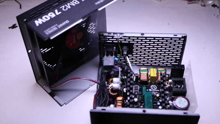
This Thermaltake power supply unit (PSU) was retired because it would turn on and run for only a short time (less than ten minutes, sometimes only a few seconds) then the computer would shut down. The fan turns, so it’s probably not simple overheating. Since it turns on, it’s not as simple as a blown fuse. But at least it didn’t fill my room with smoke, so that’s good.
It’s a shame this PSU died because it’s got nice specs, along with the convenience feature of modular connectors reducing wiring clutter inside the case.
Six screws held two halves of the enclosure together. Once removed I could slide them apart.
The 140mm fan is connected via a commodity JST-XH header, making it easy to repurpose.
This 140mm fan is larger than the 120mm fan I had just worked with, which on paper moves more air even as the fan turns at a slower (and thus quieter) speed. I’m curious to see if it is true, but I have to find a place for it first. This will be my first 140mm fan and I’m not sure what I’ll do with it just yet.
Here’s an inside view of those modular connectors, implemented as a collection of circuit board connectors. The power wires leading to this connector board is very hefty. Lettering on the insulation says 12AWG.
There were no obviously failed components inside this PSU.
And I see no obviously burned traces on the back of the circuit board. It’s a shame a high-spec PSU had to be retired, but I don’t like to take the risk of unreliable power. Bad power could damage far more expensive components (CPU, GPU, SSD) plus the annoyance factor of a computer that randomly shuts down. It’s just not worth it.