Eyoyo EM15H USB-C Portable Monitor Actually Worked The Way I Hoped It Would

PEMv3DP
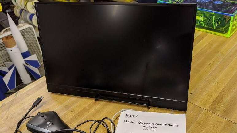
Once upon a time I decided it was a good idea to turn an old laptop screen into a portable external monitor. That was a fun project and I learned a lot, but technology has advanced and now there isn’t much point in doing the same thing again. The final nail in the coffin was the opportunity to play with an Eyoyo EM15H Portable USB-C Monitor. (*) It is just one example of a now-prolific product category that barely existed when I started my project.

The key enabling technology is the growing maturity of USB-C. Yes, it’s still something of a mess, but engineers have continued working away at chasing the dream of an universal connector. For the purpose of portable monitors, the most useful feature is the ability to carry data and power on a single cable. That makes a portable monitor much easier to set up and use than my project, where I had to wrangle both power and data cables.

Another technological evolution is how thin screens have become, driven primarily by the quest for ever thinner laptop computers. This particular monitor, complete inside its plastic enclosure, is thinner than the display I used for my project without its enclosure. I know the move from CFL to LED for backlighting has something to do with it, but I’m sure that’s only part of the story. The modern product is a fraction of the size and weight of my project.

The final piece of the puzzle is a standardized way to communicate data to the monitor. Early USB external monitors worked by presenting themselves to the system as unique video devices. This required their own specific drivers, and all video processing would be done by the USB monitor. The cheap low-powered models are only useful for mostly-static use such as PowerPoint presentations. They could not handle full screen video, and provide no 3D acceleration for games.

USB-C allows a better way. Supporting alternate modes like Thunderbolt means a USB-C display can leverage all graphics processing power on the computer and display just the rendered results. However, since USB-C is backwards compatible with old USB, it’s hard to be sure how a particular monitor is implemented until we test it firsthand. I connected this monitor to the USB-C port of my Dell 7577. I then loaded up a few video games with the graphics detail turned up high.

If the monitor is a dumb frame buffer video device, graphics performance would plummet or possibly not display at all. There’s no way a cheap external monitor can match the graphics performance of the NVIDIA GTX 1060 GPU inside the laptop.

But we had full graphics performance: full detail running at 60 frames per second. This is convincing proof the monitor is showing images rendered by the GPU inside the laptop. A lightweight, portable, single-cable easy-to-set-up external monitor with full performance is now a reality for about $150. (*) At that price point, I’m unlikely to build another external monitor of my own.


(*) Disclosure: As an Amazon Associate I earn from qualifying purchases.

Otvinta 3D Printed Hypocycloid Drive Model

Before I dive headfirst into designing a project around hypocycloid drives, I thought I should first try the low-effort test of printing up an existing design to see how it works. If it does, I get to see a printed hypocycloid drive in action. If it fails, I have data points on how to (and maybe not to) 3D print a hypocycloid drive.

Lucky for me, the very same site hosting a hypocycloid gear calculator also has a ready-to-print set of STL files for a 3D-printable hypocycloid speed reducer model. It looks like a nifty little hand-cranked demonstrator, so I fired up my 3D printer to print one of each STL. I noticed a lot of little artifacts on component mating surfaces. I was eager to see it in action, so I did only minimal cleanup with a blade before proceeding.

Hypocycloid demo model breakaway handle

One instance of theory not meeting reality was in the crank handle. The geometry was designed such that the outer grip could rotate around a center shaft. They are printed in a single piece but there’s a gap allowing the outer trip to break free and rotate about the center shaft. I’ve done this sort of designed breakaway before, but this one didn’t work well for me and it broke off at the wrong place, on the inner shaft instead of the outer handle. Oops.

Hypocycloid demo model big gap

Upon assembly I noticed a big gap, and some parts were falling out of place. It didn’t take long before I realized there were two components (a cam and a disk) where I needed to print a second unit, rather than printing just one as I had done.

Hypocycloid demo model broken

Once both disks were in place the overall system friction went up dramatically. Optimistically thinking they’re just small bumps that can wear down with a few cycles, I tried to power past the friction points. But instead of breaking through sticky portions, I broke the input drive shaft.

I asked to print another drive shaft on a more precise 3D printer. While it was printing, the device was taken apart to better clean up surface artifacts. Round 2 was far more successful, making a fun toy and sufficiently prove the concept for future experimentation.

Hypocycloid Drive Calculator by Otvinta

The best part of maker/hacker gatherings is the opportunity to meet and chat with people who introduce me to ideas and resources. At Sparklecon 2020 I met Allen Phuong who saw Sawppy roaming around and wanted to learn more. Sadly he had missed my Sawppy presentation because he was busy participating in the battle bot competition taking place at the same time, but I gave him an abbreviated version and we talked about many projects on our respective to-do lists, robotic and more.

Allen got me interested in hypocycloid gears again. It was something I briefly examined while looking for ways to build a gearbox to obtain low speed and high torque but without the backlash present in typical gearboxes. Right now the standard solution in robotics is the harmonic drive, which is an expensive solution that has specific requirements on the material used to build the flexible spline. 3D printer plastic does not meet all the requirements and hence 3D-printed harmonic drives always involve trade-offs that made me less interested.

Cycloidal drives do not have a flexible component with strict material behavior requirements, all parts remain rigid while in operation. For (near) zero backlash operation, however, it requires high dimensional accuracy. I dismissed it for this reason as 3D printing is not very precise. However, Allen asserted that 3D printers can reach the required levels so maybe it’s worth a second look. And even if I can’t get my 3D printer to meet my dimensional accuracy goals, I now have access to a few tools that I didn’t have before. Ranging from a laser cutter, to my project CNC mill, to a resin printer. All capable of far higher accuracy than my 3D printer.

There are a few tools available online to help generate profiles based on parameters I specify. Allen pointed me to the Hypocycloid Gear Calculator on Otvinta, which looks like a worthwhile starting point. The author of this site has decided to focus on Blender as the 3D tool, so if I want to make use of the results, I’ll have to learn how to translate it into Onshape or Fusion 360. But first, I can get a taste via a ready-made project.

Successful Polycarbonate Plastic Engraving Session

The first test run for CNC engraving was done on a piece of MDF. Mainly because the piece was already in the machine, surfaced, and ready to go. It was also a forgiving material in case of mistakes, but MDF doesn’t show engraved details very well.

The next session increased the difficulty level: now we have a piece of scrap polycarbonate plastic (“Lexan”) for our next engraving test. This material is interesting because it has different properties than PMMA (a.k.a. acrylic.) The latter is a popular material for laser cutting but also very brittle, very vulnerable to cracking under stress. Polycarbonate plastics are much more robust and a better choice when physical strength is important in a project.

Acrylic is also popular for laser engraving projects, but polycarbonates do not engrave or cut easily under laser power due to its different properties. It is not particularly friendly to CNC machining, either, but we’ll start with an engraving project before we contemplate milling them.

Thankfully the first session was a success, and illustrates some of the challenges of working with such materials. The toughness of the material also meant the little strings of cut chips want to remain attached to the stock, making cleanup a hassle. Upon close examination, we saw the engraved groove is slightly deeper on the left side than the right. Proof our scrap MDF working surface is not flat which was not a surprise, but “flat enough” within 4-8 thousands of an inch (1-2 sheets of normal office paper) which was better than expected.

Even with its imperfections, performance on this test indicates the machine is capable of engraving on materials we can’t use in the laser cutter. That might be useful, and a good example of how we can still learn lessons on this machine despite its flawed Z-axis and other problems. We should still fix them, of course, but the machine can already be useful while we work on those improvements.

Valuable Resource: Searchable FCC ID Database

I love taking things apart, and it’s an extra bonus if I can take something apart without destroying it. And to do that, it’s useful to have information about the innards before applying tools. Manufacturers aren’t in the habit of providing free information for what they refer to as the “non user serviceable parts inside.” However, if they want to legally sell a device that involves wireless communication, they have to submit certain information to regulatory authorities. In the United States, this is the FCC (Federal Communications Commission) and every wireless device is required to have a FCC ID and submit information to be filed with that ID.

The information presented are tailored for FCC purposes, but they are also useful for the curious consumer who want to take apart what they’ve bought. Breakdown of exterior components are common, as are pictures of disassembled device’s interior. It’s one of the many resources I consulted for my recent Hackaday how-to writeup describing how to repurpose a portable Bluetooth speaker for fun electronics projects.

As far as I can tell, the web site FCC ID.io is not run by the government agency otherwise I assume the domain would have been under fcc.gov which it is not. I couldn’t find an “About Us” page describing why the site exists, but it is a simple straightforward bare bones site. Full of useful information and lacking in useless fancy eye candy and also lacking in annoying ads. I don’t know how the site owners make money to support the site, but I hope it is working out for them and I appreciate having this resource available.

One Amazon Order, Three Identical Units, Three Shipping Boxes

Earlier I shared a tale of wasteful packaging from McMaster-Carr: using their standard box and bag system to ship a single little spacer. It’s not great, but there was a reason for the situation: the single part replaced a flawed component in an earlier (less wastefully packaged) order.

And now a different story from Amazon, whose business success is dependent on the efficiency of their logistics system. So when I ordered six Traxxas remote control monster truck wheels, I had expected them to be packed in a single box.

This looks reasonable, right?

Traxxas tire shipping expectation

That is, unfortunately, not what happened. These wheels are sold in pairs, so my order for six wheels is an order for three identical pairs, and they came in three separate boxes (each with copious packing material) as show at the top of this post.

Thinking this was bizarre, I looked for clues as to how this situation might have come to be. Examining the labels on those boxes, I saw they originated from three different distribution centers. Did Amazon’s stocking system decide to keep a single pair of these wheels at every warehouse? That seems very strange, but that is the least strange explanation I can think of for the latest episode of unnecessary packaging. The second place guess is I ordered this product at the end of its stocking period, and just happened to catch the time when there’s a lone unit waiting at each of three nearby distribution centers. That seems quite unlikely, but the potential guesses are even less likely as we move down the list.

I doubt I’ll ever know the real answer, but it will continue to puzzle me.

Toyota Mirai Water Release Switch

I have always been a fan of novel engineering and willing to spend my own money to support adventurous products. This is why, back in 2003, I was cross shopping two cars that had nothing in common except novel engineering: the Mazda RX-8 with its Wankel rotary engine and the Toyota Prius gas-electric hybrid.

Side note: it is common for car salesman to ask what other cars a particular shopper is also considering. When I tell them, it was fun to watch watch their faces as they work to process the answer.

Eventually I decided on a Mazda RX-8, which I still own. Since then I have also leased a Chevrolet Volt plug-in hybrid for three years. In fact, the exact Volt shown at the top of my Hackaday post memorializing the car. Both of those cars are no longer being manufactured. Meanwhile Toyota’s gas-electric hybrids have become mainstream, making them less personally interesting to me.

But Toyota has an entirely different car to showcase novel engineering: the hydrogen fuel cell Mirai. I had the chance to join a friend evaluating the car. He was serious about getting one, I just wanted to check it out and was not contemplating one of my own. While we were waiting for his appointment, we got in the showroom model and started looking around.

And since we were engineers, this also included digging into the owner’s manual sitting in the glovebox. The Mirai ownership experience is a fascinating blend of the familiar and the unusual, the strangest item that caught our attention was this water release switch. The manual only said it was for ‘certain situations’ but did not elaborate. We asked the sales rep and learned it was so water can be dumped before entering places where water could cause problems.

Two potential examples were actually in front of us: the Mirai parked in their showroom was sitting on a carpeted surface, where water could leave a stain. Elsewhere in the showroom, cars are parked on tile or polished concrete where water could leave a slippery surface causing people to fall. The button allows a Mirai to drain its water before moving into the showroom.

Right now commercially the Mirai is in a tough spot. It is at the end of the current product cycle, where three year old units from the same generation can be purchased off lease at significant depreciation while a far better looking next generation is on the horizon. Toyota has a lot of incentives on offer for potential Mirai shoppers. When leasing for three years, in addition to discount up front, all regular checkup and maintenance is free (no oil and filter changes here, but things like checking for hydrogen leaks instead) and a $12,000 credit for hydrogen fuel.

It was not enough to entice my friend, and I was not interested either. I believe my next car will be a battery electric vehicle.

Preparing For ROS 2 Transition Looks Complicated

Before I decided to embark on a ROS Melodic software stack for Sawppy, I thought about ignoring the long legacy of ROS 1 and going to the newer ROS 2 built on more modern infrastructure. I mean, I told people to look into it, so I should walk the walk right? Eventually I decided against putting Sawppy on ROS 2, the deal breaker was that the Raspberry Pi is not a tier 1 platform for ROS 2. This means there’s no guarantee on regular binary releases for it, or that it will always function. I may have to build my own arm32 binaries for Raspbian from source code, and I would be on my own to verify functionality. I’ve done a superficial survey of other candidates for a Sawppy brain, but for today Sawppy is still thinking with a Raspberry Pi.

But even after making that decision I wanted to keep ROS 2 in mind. Open Robotics has a  ROS 2 migration guide for helping ROS node authors navigate the transition, and it doesn’t look trivial to me. But then again, I don’t have the ROS expertise to accurately judge the effort involved.

The biggest headache for some nodes will be the lack of Python 2 support. Mainly impact ROS nodes with a long legacy of Python 2 code, it does not impact a new project written against ROS Melodic which is supposed to support Python 3.

The next headache is the fact that it’s not possible to write if/else blocks to allow a single ROS node to simultaneously support ROS 1 and 2. The recommendation is to put all specialized logic into generic non-ROS-specific code in a library that can be shared. Then have separate code tailored to the infrastructure paradigms of ROS and ROS 2. This way all the code integrating with a ROS platform can be separated, but calling into a shared library.

And it also sounds like the ROS/ROS 2 build systems conflict so they can’t even coexist side by side at the same time. Different variants of a node have to live in separate branches of a repository, with the shared library code merged across branches as development continues. Leaving ROS/ROS 2 specific infrastructure code live in their separate branches.

I can see why a vocal fraction of ROS developers are unhappy with this “best practice”. And since ROS is open source, I foresee one or more groups joining forces to keep ROS 1 alive and working with old code even as Open Robotics move on to ROS 2. Right now there are noises being made from people who proclaims to do a similar thing, saying they’ll keep Python 2 alive past official EOL. In a few years we can look back and see if those Python 2 holdouts actually thrived, and we can also see how the ROS 1/ROS 2 situation has evolved.

Wish List: Modular Sawppy Motor Controllers

One of the goals for my now-abandoned ROS Melodic Sawppy software project is something I still believe to be interesting. In contrast with the non-rover specific goals I outlined over the past few days, this one is still a rover item: I would like Sawppy motor control to be encapsulated in modules that can be easily swapped so Sawppy siblings are not required to use LX-16A servos.

My SGVHAK rover software had an infantile version of this option, and it was written in extreme time pressure to support our hack of using a RC servo controller to steer the right-front corner during SGVHAK rover’s SCaLE debut. In SGVHAK rover software, all supported motor controller code are all loaded, an unnecessary amount of complexity and overhead. It would be nice for a particular rover to bring in just the code it needed.

The HBRC crew up in the SF Bay Area (Marco, Steve, and friends) have swapped out the six drive wheels for something faster while keeping the servos for steering, so a starting point is to have options for different controls for steering and driving. But keeping in mind the original scenario was using a RC servo to hack a single steering corner, we want to make it possible to use heterogeneous motor controllers for each of ten axis of motion.

I need to better understand Rhys code to know if this is something I can contribute back to the Curio ROS Melodic software project. Rhys has stated an intent to bring in ros_control for Curio software stack. Primarily for the reasons of better Gazebo simulation, but it would also abstract Sawppy motor control logic: generic velocity controllers for driving wheels and position controllers for steering. And from there, we can have individual implementations responding to those controllers. Is that how it will work? I need to ramp up on Gazebo and ros_control before I can speak knowledgeably about it.

Learning Github Actions For Automating Verification

Once I wrote up some basic unit tests for my Sawppy rover Ackermann math, I wanted to make sure the tests are executed automatically. I don’t always remember to run the tests, and a test that isn’t getting executed isn’t very useful, obviously. I knew there were multiple tools available for this task, but lacking the correct terminology I wasted time looking in the wrong places. I eventually learned this came under the umbrella of CI/CD tools. (Continuous integration/continuous deployment.) Not only that, a tool to build my own process has been sitting quietly waiting for me to get around to using it: GitHub Actions.

The GitHub Actions documentation was helpful in laying out the foundation for me as a novice, but I learn best when the general foundation is grounded by a concrete example. When looking around for an example, I realized again one was sitting right in my face: the wemake Python style guide code analysis tool is also available as a prebuilt GitHub Action.

Using it as a template, I modified my YAML configuration file so it ran my Python unit tests in addition to analyzing my Python code style. And that it would do this upon every push to the repository, or whenever someone generates a pull request. Now we have insight into the condition of my code style and basic functionality upon every GitHub interaction, ensuring that nobody can get away with pushing (or create a pull request) with code that is completely untried and fundamentally broken. If they should try to get away with such a thing, GitHub will catch them doing it, and deliver proof. It’s not extensive enough to catch esoteric problems, but it provides a baseline sanity check.

I feel like this is something good to keep going and put into practice for all my future coding projects. Well, at least the nontrivial ones… I’ll probably skip doing it for simple Arduino demo sketches and such.

First Foray Into Python Unit Tests

When a Sawppy community member stepped up and released a ROS Melodic rover software stack, I abandoned my own efforts since there was little point in duplicating effort. But in addition to rover control, that project was also a test run for a few other ideas. I used a Jupyter notebook to help work through the math involved in rover geometry, and I started using a Python coding style static analysis tool to enforce my code style consistency.

I also wanted to start writing a test suite in parallel to my code development. It’s something I thought would be useful in past projects but never put enough focus into it. It always seemed so intimidating to build test suites that are robust enough to catch all the bugs, when it takes effort to climb the learning curve to even verify the most basic functionality. What would be the point of that? Surely basic functionality would have been verified before code is pushed to a Github repository.

Then I had the misfortune to waste many hours on a different project, because another developer did not even verify the code was valid Python syntax before committing and pushing to the repository. My idealism meant I wasted too many hours digging for another explanation, because “surely they’ve at least ran their code” and I was wrong. This taught me there’s value in unit tests that verify basic functionality.

So I brought up the Python unit test library documentation, and started writing a few basic tests for rover Ackermann geometry calculation. The biggest hurdle was that binary floating point arithmetic is not precise enough to use the normal equality comparison, and we don’t even need that much precision anyway. Calculating Sawppy steering geometry isn’t like calculating orbital trajectory for an actual mission to Mars. For production code using Python 3.5 onwards, there’s a math.isclose() available as a result of PEP 485. And for the purposes of Python unit tests, we can use assertAlmostEqual(). And how did I generate my test data? I used my Jupyter notebook! It’s a nice way to verify my wemake-compliant code would generate the same output as the original calculations hashed out in Jupyter notebook.

And finally, none of this would do any good if it doesn’t get executed. If someone is going to commit and push bad code they didn’t even try to run, they’re certainly not going to run the unit tests, either. What I need is to learn how to make a machine perform the verification for me.

Reworking Sawppy Ackermann Math in a Jupyter Notebook

The biggest difference between driving Sawppy and most other robotic platforms is the calculation behind operating the six-wheel-drive, four-wheel-steering chassis. Making tight turns in such a platform demands proper handling of Ackermann steering geometry calculations. While Sawppy’s original code (adapted from SGVHAK rover) was functional, I thought it was more complex than necessary.

So when I decided to rewrite Sawppy code for ROS Melodic (since abandoned) I also wanted to rework the math involved. I’ve done this a few times, most recently to make the calculations in C for an Arduino implementation of Sawppy control code, and it always starts with a sketch on paper so I can visualize the problem and keep critical components in mind.

Once satisfied with the layout on paper, I translate them into code. And as typically happens, that code would not work properly on the first try. The test/debug/repeat loop is a lot more pleasant in Python than it was in C, so I was happy to work with the tools I knew. But if the iterative process was even faster, I was convinced I could write even better code.

Thus I had my first real world use of a Jupyter notebook: my Sawppy Python Ackermann code. I could document my thinking in Markdown right alongside the code, and I could test ideas for simplification right in the notebook and see their results in numerical form.

But I’m not limited to numerical form: Jupyter notebooks can access a tremendous library of data visualization tools. It was quite overwhelming to wade through all of my options, I ended up using matplotlib‘s quiver plot. It plots a 2D field of arrows, and I used arrow direction to represent steering angle and arrow length to represent rolling speed. This plot gave a quick visual confirmation those numbers made sense.

In the Jupyter notebook I could work freely without worrying about whether I was adhering properly to style guides. It made the iterative work faster, but that did mean spending time to rework the code to satisfy wemake style guides. The basic logic remains identical between the two implementations.

I think this calculation is better than what I had used on SGVHAK rover, but it feels like there’s still room for improvement. I don’t know exactly how to improve just yet, but when I have ideas, I know I can bring up the Jupyter notebook for some quick experiments.

Inviting wemake to Nitpick My Python Code Style

I’m very happy Rhys Mainwaring released a ROS Melodic software stack for their Curio rover, a sibling of my Sawppy rover. It looks good, so I’ve abandoned my own ROS Melodic project, but not before writing down some notes. Part 1 dealt with ROS itself, many of which Rhys covered nicely. This post about Python Style is part 2, something I had hoped to do for the sake of my own learning and I’ll revisit on my next Python project. (Which may or may not be a robotic project.)

The original motivation was to get more proficient at writing Python code that conforms to recommended best practices. It’s not something I can yet do instinctively, so every time I tackle a new Python project I have to keep PEP8 open in a browser window for reference. And the items not explicitly covered by PEP8 are probably covered by another style guide like Google’s Python style guide.

But the rules are useless without enforcement. While it’s perfectly acceptable for a personal project to stop with “looks good to me” I wanted to practice going a step further with static code analysis tools called “linter“s. For PEP8 rules, the canonical linter is Flake8 which is a Python source code analysis tool packaged with a set of default rules for enforcing PEP8. But as mentioned earlier, PEP8 doesn’t cover everything, so Flake8 has option for additional modules for enforcing even more style rules. While browsing these packages, I was amused to find the wemake Python style guide which called itself “the strictest and most opinionated python linter ever.”

I installed wemake packages so that I can make Python code in my abandoned ROS Melodic project compliant with wemake. While I can’t say I was thrilled by all of the rules (it did get quite tedious!) I can confirm it does result in very consistent code. I’m glad I’ve given it a try, and I’m still undecided if I’m going to commit to wemake for future Python projects. No matter the final decision, I’ll definitely keep running at least plain flake8.

But while consistent code structure is useful for ease of maintenance, during the initial prototyping and algorithm design it’s nice to have something with more flexibility and immediate feedback. And I’ve only just discovered Jupyter notebooks for that purpose.

Original Goals For Sawppy ROS Melodic Project

Since a member of the Sawppy builder community has stepped up to deliver a ROS Melodic software stack, I’ve decided to abandon my own effort because it would mean duplicating a lot of effort for no good reason. I will write down some thoughts about the project before I leave it behind. It’s not exactly a decent burial, but it’ll be something to review if I ever want to revisit the topic.

Move to ROS Melodic

My previous ROS adventures were building the Phoebe Turtlebot project, which was based on ROS Kinetic. I wanted to move up to the latest long term service release, ROS Melodic, something Rhys has done as well in the Curio project.

Move to Python 3

I had also wanted to move all of my Python code to Python 3. ROS Kinetic was very much tied to Python 2, which reached end-of-life at the beginning of 2020. It was not possible to move the entire ROS community to Python 3 overnight, but a lot of work for this transition was done for ROS Melodic. Python 2 is still the official release for Melodic, but they encourage all Python modules to be tested against Python 3 and supposedly all of the core infrastructure has been made to be compatible with Python 3. Looking over the Curio project, I saw nothing offhand indicating a dependency on either Python version, so I’m cautious optimistic it is Python 3 compatible.

Conform to ROS Project Structure

I originally thought I could create a Sawppy ROS subdirectory under Sawppy’s main Github repository, but decided to create a new repository for two reasons:

  1. ROS build system Catkin imposes its own directory structure, and
  2. Existing name “Sawppy_Rover” does not conform to ROS package naming recommendations. Name must be all lowercase to avoid ambiguity between case-sensitive and case-insensitive file systems. https://www.ros.org/reps/rep-0144.html

Rhy’s Curio project solves all of these concerns.

Conform to ROS Conventions

Another motivation for a rewrite of my Sawppy code was to change things to fit ROS conventions for axis orientation and units:

  • Sawppy had been using +Y as forward, ROS uses +X as forward.
  • Sawppy had been using turn angle of positive degrees as clockwise, ROS uses right hand rule along +Z axis meaning counter-clockwise.
  • Math functions prefer to work in radians, but older code had been written in terms of degrees. Going with ROS convention of radians would skip a lot of unnecessary conversion math.
  • One potential source of confusion: “angular velocity” flips direction from “turn direction” when velocity is negative, old Sawppy code didn’t do that.

Rhy’s Curio project appears to adhere to ROS conventions.

All of that looks great! Up next on this set of notes, my original intent to practice better Python coding style with my project.

Rhys Mainwaring’s ROS Melodic Software and Simulator for Curio

When I created Sawppy, my first goal was to deliver something that could be fun for robotics enthusiasts to play with. The target demographics were high school students and up, which meant creating a software stack that is self-contained and focused enough to be easy to learn and modify.

To cater to Sawppy builders with ambition for more, one of the future to-do list was to write the necessary modules to drive Sawppy via open source Robot Operating System. (ROS) It is a platform with far more capability, with access to modules created by robotics researchers, but not easy for robotics beginners to pick up. I’ve played with ROS on-and-off since then, never quite reaching the level of proficiency I needed to make it happen.

So I was very excited to learn of Rhys Mainwaring’s Curio rover. Curio is a Sawppy sibling with largely the same body but running a completely different software stack built on ROS Melodic. Browsing the Curio code repository, I saw far more than just a set of nodes to run a the physical rover, it includes two significant contributions towards a smarter rover.

Curio Rover in Simulation

There’s a common problem with intelligent robotics research today: evolving machine learning algorithms require many iterations and it would take far too long to run them on physical robots. Even more so here because, true to their real-life counterparts, Sawppy and siblings are slow. Rhys has taken Sawppy’s CAD data and translated physical forms and all joint kinematics to the Gazebo robot simulator used by ROS researchers. Now it is possible to work on intelligent rovers in the virtual world before adapting lessons to the real world.

Rover Odometry

One of the challenges I recognized (but didn’t know how to solve) was calculating rover wheel odometry. The LX-16A servos used on Sawppy could return wheel position, but only within an approximately 240 degree arc out of the entire 360 degrees circle. Outside of that range, the position data is noisy and unreliable.

Rhys has managed to overcome this problem with an encoder filter that learned to recognize when the servo position data is unreliable. This forms the basis of a system to calculate odometry that works well with existing hardware and can be even faster with an additional Arduino.

ROS Software Stack For Sawppy

Several people have asked me for ROS software for Sawppy, and I’m glad Rhys stepped up to the challenge and contributed this work back to the community. I encourage all the Sawppy builders who wanted ROS to look over Rhys’ work and contribute if it is within your skills to do so. As a ROS beginner myself, I will be alongside you, learning from this project and trying to run it on my own rover.

https://github.com/srmainwaring/curio

(Cross-posted to Sawppy’s Hackaday.io page)

Undersized Spacer Promptly Replaced By McMaster-Carr

Living in the Los Angeles area has its ups and downs. As a maker tinkerer, one of the “up” is close proximity to a major McMaster-Carr distribution facility. When introducing McMaster-Carr to friends who are not already aware of them, I say “they sell everything you’d need to set up a factory.” It is a valuable resource that becomes even more valuable when deadlines loom because of their quick service and willing to ship orders of any quantity. I receive my orders the next day, and in case of a real crunch, I can fight LA traffic to get same-day satisfaction at their will-call pickup window.

Selection, speed, and customer service are their strengths, but that comes with tradeoff in cost and efficiency. Nothing illustrated this more clearly than a recent experience with one of my McMaster-Carr orders. My shipment included a number of small aluminum spacers of a particular inner/outer diameter. And the length is obviously the most critical dimension for a spacer… but one of them was too short. It appears these were cut on automated CNC lathes and an incomplete end piece of stock fell into the pile of finished products.

I reported this to McMaster-Carr and they immediately sent out a replacement spacer delivered the next day.

One.

Single.

Spacer.

As a customer I can’t complain: I reported my problem and they fixed it immediately at their expense. It does make me happy that I only had to wait an extra day and I plan to continue buying from McMaster-Carr for my hardware needs. I don’t have an alternative to propose, so this was probably the best possible outcome.

All that said, it still feels incredibly wasteful.

Wasteful McMaster Carr packaging

VGA Signal Generation with PIC Feasible

Trying to turn a flawed computer monitor into an adjustable color lighting panel, I started investigating ways to generate a VGA signal. I’ve experimented with Arduino and tried to build a Teensy solution, without success so far. If I wanted full white maybe augmented by a fixed set of patterns, Emily suggested the solution of getting a VGA monitor tester.

They are available really cheaply on Amazon. (*) And even cheaper on eBay. If I just wanted full white this would be easy, fast, and cheap. But I am enchanted with the idea of adjustable color, and I also want to learn, so this whole concept is going to stay on the project to-do list somewhere. Probably not the top, but I wanted to do a bit more research before I set it aside.

One thing Emily and I noticed was that when we zoomed in on some of these VGA monitor testers, we can tell they are built around a PIC microcontroller. My first thought was “How can they do that? a PIC doesn’t have enough memory for a frame buffer.” But then i remembered that these test patterns don’t need a full frame buffer, and furthermore, neither do I for my needs. This is why I thought I could chop out the DMA code in the Teensy uVGA library to make it run on a LC, keeping only the HSYNC & VSYNC signal generation.

But if I can get the same kind of thing on a PIC, that might be even simpler. Looking up VGA timing signal requirements, I found that the official source is a specification called Generalized Timing Formula (GTF) which is available from the Video Electronics Standards Association (VESA) for $350 USD.

I didn’t want to spend that kind of money, so I turned to less official sources. I found a web site dedicated to VGA microcontroller projects and it has tables listing timing for popular VGA resolutions. I thought I should focus first on the lowest common denominator, 640×480 @ 60Hz.

The PIC16F18345 I’ve been playing with has an internal oscillator that can be configured to run at up to 32 MHz. This translates to 0.03125 microseconds per clock, which should be capable of meeting timing requirements for 640×480.

I thought about leaving the PIC out of the color signal generation entirely, have a separate circuit generate the RGB values constantly. But I learned this would confuse some computer monitors who try not to lose data. So we need to pull RGB values down to zero (black) when not actively transmitting screen data. It would be more complex than just focusing on HSYNC/VSYNC but not a deal breaker.

[UPDATE: I continued this project with an ESP32.]


(*) Disclosure: As an Amazon Associate I earn from qualifying purchases.

VGA Investigation Continues with Teensy

After deciding the Arduino VGAX library was not going to serve my needs, I started researching other ways to generate a VGA signal. What became clear pretty quickly was that a standard Arduino isn’t fast enough to meet timing requirements without additional hardware support. So solutions that work entirely in software will be roughly as limited as VGAX, and those that work for higher resolutions require auxiliary hardware.

Given that fact, I started looking at VGA signal generation by a faster line of microcontrollers: the Teensy line. I have on hand a Teensy LC and a Teensy 4, and I found this thread on Teensy forums announcing a library for generating VGA signal strictly in software, no auxiliary hardware. Browsing through the Github repository of this uVGA library, it looked quite promising. However, the primary target platform is the Teensy 3. I bracket it above and below with a Teensy 4 and a Teensy LC. Would one of them be able to run this code?

An attempt to compile an uVGA example for the Teensy LC failed:

In file included from /home/roger/Arduino/libraries/uVGA/examples/HelloWorldColour/HelloWorldColour.ino:3:0:
/home/roger/Arduino/libraries/uVGA/uVGA.h:297:16: error: 'TCD_t' in 'class DMABaseClass' does not name a type
DMABaseClass::TCD_t *edma_TCD; // address of eDMA TCD registers

My best guess is that the Teensy LC lacks the direct memory access (DMA) capability uVGA requires. I’ve already been foiled once on the reduced hardware capability on a Teensy LC, so this was no surprise. DMA is critical for shuttling memory back and forth without bogging down the CPU for timing-critical tasks (like VGA signal generation) so this requirement is unlikely to be lifted.

However, since my goal is only to generate a signal outputting a single color to the entire screen, I don’t really need to shuttle data from a video frame buffer for display. If I’m willing to dig into the uVGA code, I can probably find a way to bypass the commands moving memory and accomplish my very specific goal.

Before I start doing work, though, I should see what happens when I try compiling the same uVGA example for the Teensy 4:

In file included from /home/roger/Arduino/libraries/uVGA/examples/HelloWorldColour/HelloWorldColour.ino:8:0:
/home/roger/Arduino/libraries/uVGA/uVGA_valid_settings.h:59:17: note: #pragma message: No resolution defined for this CPU frequency. Known CPU frequency: 240Mhz, 192MHz, 180Mhz, 168Mhz, 144Mhz, 96Mhz, 72Mhz, 48Mhz

It looks like the uVGA library has some hard-coded dependencies on a Teensy CPU’s frequency, and it doesn’t know what to do with the high speed of a Teensy 4. I expect that speed will open up new capabilities, but someone has to teach uVGA about a Teensy 4 before that could happen. If I’m willing to dig into uVGA code, this would be a more productive and forward-looking way to go and a positive contribution to the open source community.

But before I can realistically contemplate that project, I’ll need to become a lot more knowledgeable about VGA timing requirements.

Sparklecon 2020 Day 2: Arduino VGAX

Unlike the first day of Sparklecon 2020, I had no obligations on the second day so I was a lot more relaxed and took advantage of the opportunity to chat and socialize with others. I brought Sawppy back for day two and the cute little rover made more friends. I hope that even if they don’t decide to build their own rover, Sawppy’s new friends might pass along information to someone who would.

I also brought some stuff to tinker at the facilities made available by NUCC. Give me a table, a power strip, and WiFi and I can get a lot of work done. And having projects in progress is always a great icebreaker for fellow hardware hackers to come up and ask what I’m doing.

Last night I was surprised to learn that one of the lighting panels at NUCC is actually the backlight of an old computer LCD monitor. The LCD is gone, leaving the brilliant white background illuminating part of the room. That motivated me to dust off the giant 30-inch monitor I had with a bizarre failure mode making it useless as a computer monitor. I wasn’t quite willing to modify it destructively just yet, but I did want to explore the idea of using the monitor as a lighting panel. Preserving the LCD layer, I can illuminate things selectively without overly worrying about the pixel accuracy problems that made it useless as a monitor.

The next decision was the hardest: what hardware platform to use? I brought two flavors of Arduino Nano, two flavors of Teensy, and a Raspberry Pi. There were solutions for ESP32 as well, but I didn’t bring my dev board. I decided to start at the bottom of the ladder and started searching for Arduino libraries that generate VGA signals.

I found VGAX, which can pump out a very low resolution VGA signal of 160 x 80 pixels. The color capability is also constrained, limited to a few solid colors that reminded me of old PC CGA graphics. Perhaps they share similar root causes!

To connect my Arduino Nano to my monitor, I needed to sacrifice a VGA cable and cut it in half to expose its wires. Fortunately NUCC had a literal bucketful of them and I put one to use on this project. An electrical testing meter helped me find the right wires to use, and we were in business.

Arduino VGAX breadboard

The results were impressive in that a humble 8-bit microcontroller could produce color VGA signals. But they were not very useful in the fact that this particular library is not capable of generating full screen video, only part of the screen was filled. I thought I might have done something wrong, but the FAQ covered “How do I center the picture” so this was completely expected.

I would prefer to use the whole screen in my project, so my search for signal generation must continue elsewhere. But seeing VGAX up and running started gears turning in Emily’s brain. She had a few project ideas that might involved VGA. Today’s work gave a few more data points on technical feasibility, so some of those ideas might get dusted off in the near future. Stay tuned. In the meantime, I’ll continue my VGA exploration with a Teensy microcontroller.

Sparklecon 2020: Sawppy’s First Day

I brought Sawppy to Sparklecon VII because I’m telling the story of Sawppy’s life so far. It’s also an environment where a lot of people would appreciate the little miniature Mars rover running amongst them.

Sparklecon 2020 2 Sawppy near battlebot arena

Part of it was because a battlebot competition was held at Sparklecon, with many teams participating. I’m not entirely sure what the age range of participants were, because some of the youngest may just be siblings dragged along for the ride and the adults may be supervising parents. While Sawppy is not built for combat, some of the participants still have enough of a general interest of robotics to took a closer look at Sawppy.

Sparklecon 2020 3 Barb video hosting survey

First talk I attended was Barb relaying her story of investigating video hosting. Beginning of 2020 ushered in some very disruptive changes in YouTube policies of how they treat “For Kids” video. But as Barb explains, this is less about swear words in videos and more about Google tracking. Many YouTube content authors including Barb were unhappy with the changes, so Barb started looking elsewhere.

Sparklecon 2020 4 Sawppy talk

The next talk I was present for was my own, as I presented Sawppy’s story. Much of the new material in this edition were the addition of pictures and stories of rovers built by other people around the country and around the world. Plus we recorded a cool climbing capability demonstration:

Sparklecon 2020 5 Emily annoying things

Emily gave a version of the talk she gave at Supercon. Even though some of us were at Supercon, not all of us were able to make it to her talk. And she brought different visual aids this time around, so even people who were at the Supercon talk had new things to play with.

Sparklecon 2020 6 8 inch floppy drive

After we gave our talks, the weight was off our shoulders and we started exploring the rest of the con. During some conversation, Dual-D of NUCC dug up an old school eight inch floppy drive. Here I am failing to insert a 3.5″ floppy disk in that gargantuan device.

Sparklecon 2020 7 sand table above

Last year after Supercon I saw photographs of a sand table and was sad that I missed it. This year I made sure to scour all locations to make sure I can find it if it was present. I found it in the display area of the Plasmatorium drawing “SPARKLE CON” in the sand.

Sparklecon 2020 8 sand table below

Here’s the mechanism below – two stepper motors with belts control the works.

Sparklecon 2020 9 tesla coil winding on lathe

There are full sized manual (not CNC) lathe and mill at 23b shop, but I didn’t get to see them run last year. This year we got to see a Tesla coil winding get built on the lathe.

For last year’s Sparklecon Day 2 writeup, I took a picture of a rather disturbing Barbie doll head transplanted on top of a baseball trophy. And I hereby present this year’s disturbing transplant.

Sparklecon 2020 WTF

Sawppy has no idea what to do about this… thing.