AU Optronics B101EAN01.5 Backlight Power

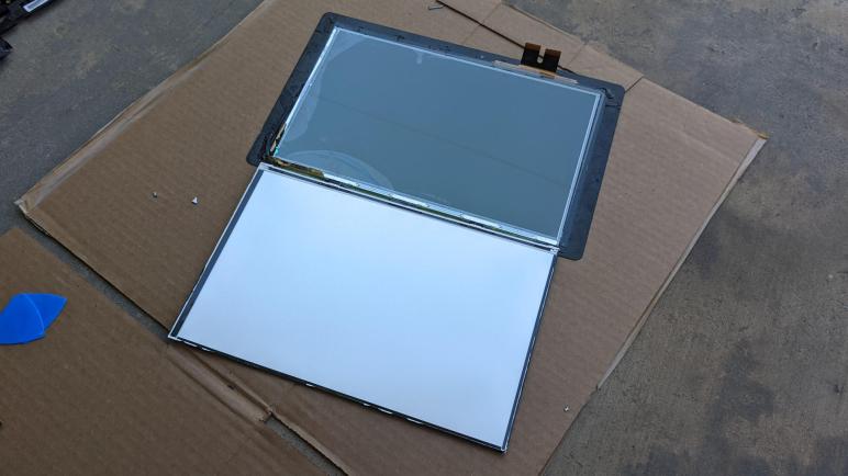
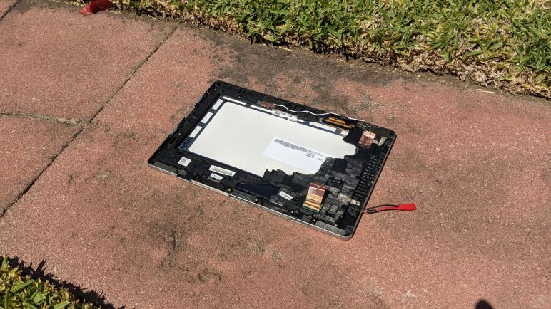
I’ve pulled the LED backlight illumination panel out of an AU Optronics B101EAN01.5 LCD panel, which was in turn salvaged from an Acer Aspire Switch 10 (SW5-012) tablet/laptop convertible. I want to see if I can get it to light up. Using my multimeter I found test points corresponding to all six control lines on the backlight, and soldered wires to all of them. The next task is to determine what these wires are.

The other end of those wires were crimped and assembled into a six-pin connector with 0.1″ spacing. I first arranged them in whatever happened to be convenient, but then I changed my mind and rearranged them to be in the same order as that on the backlight cable. From top to bottom: Power, ground, FB1, FB2, FB3, and FB4.

This gave me something suitable for breadboard exploration. I have two hypothesis about what the FB connectors are. Since power and ground were already identified, I thought maybe these are control lines (gates) for MOSFETs in line with each string, which implies I could turn on a LED string by pulling its signal high. But if I look at precedence set by the LG LP133WF2(SP)(A1) panel I took apart earlier, these could be four current sinks for four LED strings.

To test both concepts simultaneously, my breadboard exploration wired one string to a pull-up resistor in case FB is a MOSFET gate, and another string to a pull-down resistor in case it is LED current sink.

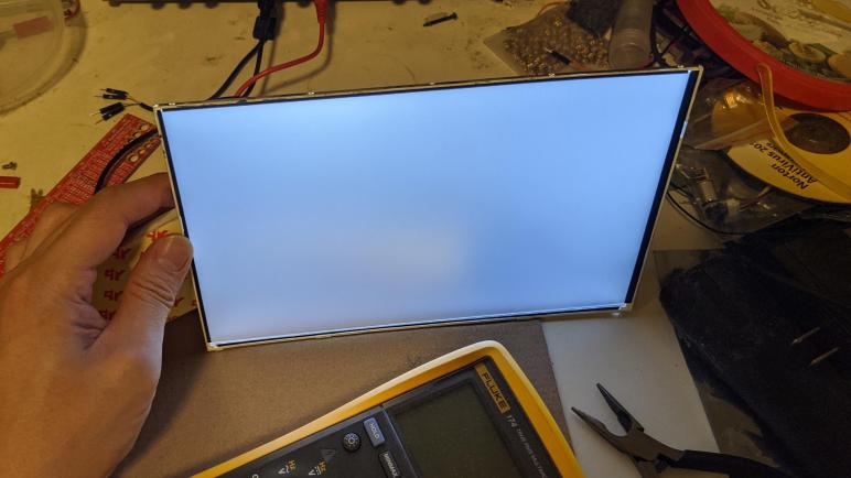
I started seeing a dim glow when I turned the power supply up to 17V. To determine which hypothesis was correct, I removed the pull-down resistor and it went dark. So FB1 through FB4 are current sinks for four strings. As a double-check, I calculated voltage drop across the pull-down resistor and calculated the current flow to be 1.4mA. This is far too high for a MOSFET gate but completely consistent with current-limiting resistor for a dimly lit LED.

Hooking up a current-limiting resistor to each of FB1 through FB4, the backlight has dim but usable illumination starting at about a 15.6V drop across an individual LED string. Whenever I find a project for this light, I will need to either solder more permanent current-limiting resistors, or find an intelligent LED controller with a more efficient current-limiting control scheme.

There is one remaining mystery: If the VOUT wire is voltage source, and FB1 through FB4 are current sinks, why is there a line connected to the ground plane on the control circuit board? It feels like there’s another aspect of this backlight I have yet to discover. Or possibly destroyed by clumsy overvoltage on my part. Either way, it doesn’t seem to be critical for illuminating this backlight, so I’ll leave that mystery for another day.

AU Optronics B101EAN01.5 Backlight Wiring

I have a broken Acer Aspire Switch 10 (SW5-012) that I have taken apart. Among the pieces I salvaged was the screen, an AU Optronics B101EAN01.5 whose 1280×800 resolution is not terribly interesting in this era when even cell phones have higher resolution displays. So I decided the most interesting thing to do is to liberate its LED backlight for potential future projects.

The backlight connector has six visible conductors. Two conductors are wider than the rest, which imply power and ground to me. There is a test point labeled VOUT adjacent to this connector, and my meter confirms it corresponds to the topmost wide conductor. The meter also confirmed the second wide conductor has continuity to the ground plane of this circuit board, so power and ground confirmed.

What does that mean for the four remaining thin conductors? Looking around the backlight control IC, I looked for a likely group of four test points and found FB1, FB2, FB3 and FB4. Meter confirms they correspond to the remaining four conductors on the backlight cable. “FB” probably doesn’t mean Facebook in this context, but I’m not sure what it would represent. I’m just glad they were numbered.

As for the backlight control IC itself, the large AUO letters say it is something AU Optronics produced for internal consumption. The earlier LG panel project found a TI TPS61187 chip with publicly available documentation, but here I found no documentation for an AUO L10716 controller. Since the chip is so tiny it’s pretty probable I’ve misread the numbers, but no search hits on the variations I could think of either: LI0718, L10216, etc. If I had found a test point labeled PWM I would be tempted to see if I can get it running with an Arduino PWM signal, but I saw test points labeled SCL and SDA telling me this is an I2C peripheral and my skill level today isn’t good enough to reverse engineer it without official documentation of its I2C protocol.

So instead of trying to interface with the existing backlight control chip as I did on the LG backlight, here I will interface with the backlight LEDs directly. I found test points corresponding to all six wires on the backlight connector and soldered wires to all of them. Then I used hot glue to help hold them down and relieve strain, as I don’t want to lift a pad again!

With the wires securely attached, I need to figure out what they actually do.

Acer Aspire Switch 10 (SW5-012) Backlight Removal

While I took apart the base unit of this dead Acer Aspire Switch 10 (SW5-012) tablet/laptop convertible, the main display had been left under the punishing direct heat of southern California summer sun. I don’t like fighting glue, but heat at least helps reduce their tenacious grip. I pulled out my prying tools from iFixit and plunged into the seam between gray and black plastic surrounds holding its AU Optronics B101EAN01.5 screen in place.

The double-sided adhesive foam tape was thickest around the left and right sides, gripping tightly enough that I broke the frame on both sides trying to peel them off. There were slightly less of it across the top, and surprisingly little across the bottom.

I had hoped the LCD module would pop free once the touchscreen digitizer glass had been freed from its frame, similar to how an Amazon Fire tablet was put together. But no such luck, there appears to be more adhesive involved.

Once I pushed a pick into the gap between the digitizer glass and the LCD polarizer, I realized the bad news: they have been glued together across the entire visible front surface of the screen. It’s going to take a lot of effort to separate them and I don’t see how it could possibly be worth the effort.

My objective here is the LED backlight, so just as I did for the Chromebook cracked screen and the Amazon Fire screen, I peeled back the black tape holding the LED backlight to the LCD. Starting with the bottom section to expose the integrated driver board.

I am starting to recognize the signs of a LED backlight power connection: a few connectors separate from the high-density connectors used for controlling LCD pixel data. An inductor and a diode for voltage boost conversion, and an IC controlling it all.

The black tape holding this display module together is much more difficult to remove than those encountered on previous screen backlight salvage projects. The glossy substrate is weaker than the adhesive, causing it to easily stretch and break. Now that I’ve identified the portion I cared about for my project, I pulled out a blade and cut the rest of the tape allowing me to open up this display module.

Once the backlight folded away from the LCD pixel array, I can see I’ve already cracked at least one LCD glass layer in my effort to pry it from the front digitizer glass. I’m not even going to try to salvage the polarizer filter from this one, so my blade continued its work cutting all pixel data lines to free the backlight for further examination.

Acer Aspire Switch 10 (SW5-012) Hinge

A laptop’s keyboard may be the main interface point with the user, but the hinge mechanism of a laptop computer is an often overlooked critical mechanism that can make or break the entire ownership experience. The challenge is even more profound for tablet/laptop convertibles like this Acer Aspire Switch 10 (SW5-012) since it had to detach as well. Digging into this mechanism as part of my teardown unveiled a very intricate but also extremely robust piece of mechanical engineering.

The first challenge is, of course, figuring out where to start opening it up. I pried on the back plate hoping it would pop loose. It did, sort of, in a irreversible and destructive way.

But with it open, I could tell there’s an angled metal spine to this hinge and there are probably fasteners hiding under the rubbery material that cushions the main display unit when it is attached to this base.

The two rubbery cushions were held with double sided tape. Once peeled off, each exposed two screws that helped hold the top plate in place. They’re not the only fastening mechanism, though, there were many other places where the top plate held on for its life and it did not come loose willingly. I ended up breaking it into several pieces.

Top plate removal exposed many more fasteners, several of which held the backplate.

And the remaining fasteners held the metal spine to the bottom section. This is easily the highest density of screws in this machine holding everything together, reinforcing the critical nature of this component.

I finally freed the nine-conductor pogo connector that was one of my objectives for taking this retired computer apart. There are also a few magnets that held the display module in place as a simple and elegant “Acer Smart Hinge”. They will also be salvaged for potential future fun.

And now with the hinge thoroughly taken apart, I retrieved the main module which had been baking in the sun in preparation for fighting annoying glue.

Acer Aspire Switch 10 (SW5-012) Keyboard

There were two high density circuit boards in the base of an Acer Aspire Switch 10 (SW5-012) tablet/laptop convertible. One handled general connectivity to the main display unit of the computer, and another purely focused on touchpad input. The third, while technically a circuit board as well, is less dense and is the array of switches that implement the keyboard of this machine.

Typing on this keyboard has been a good experience, at least as far as membrane keyboards go. Key travel felt good, and the scissor mechanism sturdily held actions crisp. Even though this is a thin and light (very much so for its day, and still respectably so today) convertible, it never felt flimsy. As I dig inside, I could see what gave it such a solid feel: metal structural plates and lots of mounting points.

The sheer number of mounting points make it rigid, but they are not held with removable fasteners. They are held with plastic rivets probably for cost of manufacturing, but this also meant there’s no way to nondestructively replace the keyboard module. I start by peeling the keyboard surround from the metal chassis plate. Pop, pop, pop, went those rivets as I pulled.

Once the keyboard surround was removed, I could see a magnet that I can harvest (below where the right arrow key used to be) and the remainder will become plastic landfill. The keyboard itself is held to the metal plate by even more plastic rivets, and once I pop them off to remove the keyboard the metal plate should be clean enough for general scrap metal.

Here is a closeup of the control key in the lower left corner, and the numerous gray plastic rivets holding the keyboard module in place.

I popped off the control keycap to take a closer look at the scissor mechanism on this keyboard. I imagine there are only a few major suppliers/styles for this mechanism, unless there’s a product differentiation I’m ignorant about motivating keyboard makers to custom design their own. In any case, my interest was seeing if I can cannibalize the scissor mechanism to repair a missing key on the HP Mini (110-1134CL) netbook from NUCC.

Sadly while the two scissors mechanisms are very similar to each other, they are not identical. Perhaps someone skilled with modifying watchmaker–level mechanisms can hack the pieces to fit, but that is beyond my skill level today. I’ll leave this keyboard alone for now and switch focus to this computer’s robust hinge mechanism.

Acer Aspire Switch 10 (SW5-012) Base Circuitry

When I looked at the reinforcement rib network on the bottom plate I just pulled off, I saw it was not symmetric. The reason became clear when I looked at the internal circuitry of this keyboard base, those asymmetric gaps in reinforcement ribs were to make room for a circuit board and the data cables connecting it to the keyboard array.

Two large connectors dominate the center of this board, one with four conductors and another with five. These nine conductors directly connect to the nine pogo pins connecting to the main unit of this computer. If there were only four conductors I would have been tempted to see if it was direct USB, but there are nine conductors and I don’t have a good idea what might be going on.

I thought the USB hypothesis had merit when I found one of the ICs on board is a USB hub controller. It would have been a valid way to implement this keyboard base: turn the keyboard, the touchpad, and the USB port into individual USB devices connected to a common hub. But USB isn’t a protocol I’ve worked with, it works at far higher speed than any diagnostics tools I have on hand, and I’m not particularly motivated to get this running because if I did, what would I get? A keyboard and a mouse pointer device. I already have enough of those.

So I continued to merrily tear things apart looking for interesting sights as I went. The other circuit board in the base is entirely dedicated to the touchpad. The controller IC on this board is from Synaptics, a very popular supplier for touch hardware. The metal frame came apart in two separate pieces.

It works as a hinge to act against a physical button handling taps on this touchpad. I’m amused that there’s only a single button, they must correlate this button with finger positions in order to infer left or right click.

Flipping it over, I see the cosmetically perfect top surface of the touchpad.

As is typical of touchpads, that top surface is merely a façade covering a network of electrical wires that is used by the Synaptics IC to sense finger position. This is analog voodoo I don’t understand in the least, and neither do most other people, which is why companies like Acer pay Synaptics to figure out. The façade is a sticker that I could peel off to expose the circuit pattern below.

Yep, it’s an array of repeated patterns. Yep, the individual elements will help determine position of our fingers. Beyond those generalities, I have no clue. I’ve taken apart many laptop touchpad like this, and no two has used the same pattern on their circuit boards. Voodoo, I say! Thankfully, with its array of on/off switches, a keyboard is more straightforward than the analog magic of a touchpad.

Acer Aspire Switch 10 (SW5-012) Bottom Plate

The Acer Aspire Switch 10 (SW5-012) was a Windows 8 convertible tablet/laptop that easily separated into two parts. For my teardown purposes, this meant I could work on the keyboard base while the main display module is sitting in the sun to soften the glue holding it together.

When this computer is in laptop mode, the main module communicates with its keyboard base through these robust-looking pogo connectors. I’m not sure I can find a good way to reuse them, but I’m definitely trying to salvage them intact so I’d have the option in the future. It was pretty trivial to pull the top part, and extracting its counterpart from this base is my current objective.

I flipped the base over and saw several straightforward Philips screws. Laptop fasteners are usually hidden, or require an annoying esoteric tool, so this was a delightful surprise. I pulled out a screwdriver, removed (almost) all of them and pulled off the base plate.

A loud crack announced the fact that there were actually two more screws hidden under a gray strip of plastic, and pulling the base apart destroyed plastic around these hidden screws. I’m glad I have no intention of putting this thing back together into working order.

Flipping the bottom plate over, we can see the internal structure. It has a surprising complex of reinforcement ribs. Interestingly, the network is not symmetric. Not top-bottom, and not left-right, yet it speaks to a clear purpose that was not obvious from just looking at this piece.

In any case, these reinforcement ribs reminded me that this laptop, as small and thin as it was, never felt flimsy or gave the impression it would flex and break apart in my hands. Credit goes to reinforcement ribs like these and other thoughtful touches scattered throughout the design of this tablet.

There are two pieces of shiny metal that appear to serve no immediate purpose, my guess is that they are counterweights like I tend to see in other tablet/laptop convertibles. The one on the right has a thin strip of plastic as electrical insulation so it doesn’t short out the circuitry, and those circuit boards are likely the reason why reinforcement ribs are not symmetric.

Acer Aspire Switch 10 (SW5-012) Teardown

With the successful relight of a salvaged Amazon Fire tablet backlight, I’m ready to begin the final chapter of my journey with this Acer Aspire Switch 10 (SW5-012). I’m not the original owner of this machine, so it was never my day-to-day computer. It was retired when it would no longer power-up, and the charger has been lost in the time it was sitting around gathering dust. That nonworking state was how I got it as something to play with.

I diagnosed the power-up problem to a loose cable, and I worked around the lost charger with a hacked-up power connector. That was enough for me to power this system back up. I found it didn’t want to run Linux, but it could run modern Windows 10 surprisingly well. And I didn’t even have to buy another Windows license, as the Windows 8 license embedded in hardware seemed to work just fine. And I undertook some projects like removing its webcam module for security. Because no hacker on the internet can activate a webcam that’s sitting detached in a zip lock bag in another room.

But a computer that runs modern Windows 10 “surprisingly well” for its age is not the same as a computer that runs it well in a useful sense. It’s still an old computer showing its age across the board. Limited RAM, cramped storage, and most personally unsatisfying for me, a low resolution screen. The CPU is not the ill-fated Clover Trail series, but it is still quite slow and is a 32-bit only CPU cut off from modern features of 64-bit operating systems. 32-bit support has already been dropped by MacOS, Ubuntu, even Chrome OS is 64-bit only nowadays.

Finally the system failed again, with the familiar symptom of failing to power up when the power button is pressed. However, this time it was not the loose cable and I failed to find another explanation. It was then retired and I performed a partial disassembly, pulling out its mainboard for a play with a hot air rework station.

I think it is time for me to finish the teardown the rest of the way. The battery pack has already been freed and I think that two-cell lithium ion pack has a future in another project down the line. That leaves the screen, whose low resolution makes it uninteresting as a display but now with two backlight projects under my belt I’m going to see if I can salvage this backlight. Then I’ll see what else might be interesting to salvage from this machine.

Most of what’s left on this convertible laptop main unit were glued together, and I hate fighting glue which is why it halted my earlier teardown. But I have to do it if I want that backlight, so I started thinking about heating up the module to soften the glue. I used to do this with a heat gun, and with the Amazon Fire tablet I used the heated print bed of a retired 3D printer. But we’re now entering the uncomfortably hot phase of Southern California summer. So there’s no need to consume electricity: I can just set this thing out on a brick and let it warm up in the sun and turn my attention to the base section.

Hot Air Station Amateur Hour

A hot air station is one of the standard tools for working with surface-mount electronics, mostly in the context of rework to fix problems rather than initial assembly. In addition to manuals for individual pieces of equipment, there are guides like this one from Sparkfun. My projects haven’t really needed me to buy one, though that’s debatable whether that’s a cause or an effect: perhaps I design my projects so I don’t need one, because I don’t have one!

Either way I knew some level of dexterity and skill are required to use the tool well, and the best way to get started is to start playing with one in a non-critical environment. Shortly before the pandemic lockdown, I had the opportunity when Emily Velasco offered to bring her unit to one of our local meetups for me to play with. I had a large collection of circuit boards removed from tearing down various pieces of equipment. I decided to bring the mainboard from an Acer Aspire Switch 10, which was a small Windows 8 laptop/tablet convertible that I had received in an as-is nonfunctional state. I was able to get it up and running briefly but I think my power supply hack had provided the wrong voltage. Because a few months later, it no longer powered up.

Using the hot air rework station, I started with small SMD components. A few capacitors, transistors, things of that nature. I could take them off, and put them back on. I have no idea if they remained functional, that will be a future test at some point.

The USB ports and mini HDMI port on this device were surface mounted and I tried them next. I could remove them with the hot air rework station, but I couldn’t reinstall them. I got close so I believe this is a matter of practice and improving my technique.

Those connectors had relatively few large connection points, I tried my luck with larger chip packages on board. These were memory modules and flash storage modules, fairly large chips with electrical connections underneath where no soldering iron could reach them. My success rate here is similar, of being able to pull them off but not put them back on. I was less optimistic I could get this to work with practice, since these are ball grid array (BGA) modules and I would have to re-ball them to reinstall properly.

The largest chip on the board was the Intel CPU. I suspect there are heat dissipation measures in circuit board copper layers, similar to how a DRV8833 handles cooling with PowerPAD. Whatever is going on, I could not remove the CPU at all with this hot air rework station.

This was a fun introductory hot air play session, I look forward to more opportunities to learn how to use hot air once we can safely hold hacker meetups again. Here’s the final dissected cadaver:

Hot air rework session end

Remove Camera From Acer Aspire Switch 10

When the Acer SW5-012 (Aspire Switch 10) was received in a non-functioning state, it had a sticker covering the webcam lens applied by the previous owner. This is a common modification from owners who are concerned about malicious hackers activating the camera at unauthorized times. Some computer makers are finally meeting customer demand by placing physical shutters over webcams, but until that becomes commonplace, we’ll continue to have stickers/tabs/post-it notes covering webcams.

Removing the camera module would be a far more secure solution if the webcam is not to be used anyway. While impractical for some difficult-to-disassemble devices like an Apple iPad, we’ve already cracked open this Acer and test the concept. It turned out to be a straightforward exercise. The camera module is a distinct unit, the ribbon cable detaches from the motherboard easily, and it was only held in place by what felt like double-sided tape.

Acer Aspire Switch 10 Blinded

With five minutes of removing the back panel of the machine, the camera module was removed. The only lettering on it said CIFDF31_A2_MB and a web search on that designation returned several vendors happy to sell a replacement module. Sadly no technical information was found in a cursory search, so we won’t be trying to drive it with a PIC micro controller or anything. It’ll just sit in a zip lock bag for now.

And this intentionally-blinded Acer tablet is now available for use by house guests who are wary of hackers getting into the camera: no hacker in the world can activate a camera that is sitting in a zip lock bag in another room.

Acer Aspire Switch Runs Windows 10 (Fall Creator’s Update)

After Secure Boot discouraged me from putting a Linux variant on the recently revived Acer SW5-012 (Aspire Switch 10) convertible laptop, I tried to replace the existing Windows 8 installation (locked with passwords I don’t have) with the latest Windows 10.

The first thing to check is to look in the BIOS and verify the CPU is not a member of the ill-fated Intel Clover Trail series, whose support was dropped. Fortunately, the machine uses a newer CPU so I can try installing Windows 10 Fall Creator’s Update. I had an installation USB flash drive built with Microsoft’s Media Creation Tool.

I needed an USB OTG cable to start the installation. Once in progress, I deleted the existing Windows 8 system partition (~20 GB) and the recovery image partition (~7 GB), leaving the remaining two system partitions intact before proceeding.

When Windows 10 initially came up, there were significant problems with hardware support. The touchscreen didn’t work, there was no sound, and the machine was ignorant of its own battery charge level. Fortunately all of these hardware issues were resolved by downloading and running the “Platform Drivers Installer” from Acer’s support site.

After the driver situation was sorted out I started poking around elsewhere on the system and found a happy surprise on Windows licensing. Since I couldn’t get into the Windows 8 installation, I couldn’t perform a Windows upgrade. Because I performed a system wipe, I thought I lost the Windows license on this machine. But I was wrong! I don’t know exactly what happened, but when I went to look at the computer’s information, it claims “Windows is Activated.”

The sticker on the bottom of the machine says it came with Windows 8 Pro. The new Windows 10 installation activated itself as Windows 10 Home. It is technically a step down from Pro to Home but I am not going to complain at the unexpectedly functional Windows license.

The machine outperformed my expectations. It handily outperformed my other computers with Intel Atom processors. I think the key part is its 2GB of RAM, double the 1GB RAM of the other Atom machines. The machine is surprisingly usable relative to its Atom peers.

Some credit is due to Acer for building a low-end computer in 2014 that is still capable on the software of 2017 (almost 2018.)

[UPDATE: I figured out Windows 10 activates itself on Windows 8 machines.]

Acer Aspire Switch is Linux Unfriendly

Now that the hardware of an Acer SW5-012 (Aspire Switch 10) is back up and running, the focus turns to software. Windows 8 is installed but locked with passwords I don’t have. I didn’t care much for Windows 8 anyway, and whatever data exists is not mine to recover. So – a clean wipe is in order.

As with the Latitude X1, my first thought was to turn this little old machine into an almost-Chromebook with Neverware CloudReady. And just like with the Latitude X1, the attempt was foiled. The Latitude X1 was too old and did not support some processor features required by CloudReady. The Acer problem is just the opposite – the hardware is too new and deliberately blocks the installation.

The blocking mechanism is Secure Boot, which according to its own web site is a “security standard developed by members of the PC industry to help make sure that a device boots using only software that is trusted by the Original Equipment Manufacturer.” I would describe it with different terms. Either way, trying to install CloudReady – or a Linux distribution – results in the error screen “Secure Boot Error”.

Intentional or not, this puts the Acer in a bad state. It gets stuck neither fully on nor off, the screen dark but burning battery power and making itself warm. I had to disassemble the computer again to pull the battery from the main circuit board in order to reboot the machine.

In theory Secure Boot can be disabled, but various efforts by other people on the internet indicated this isn’t straightforward. I certainly had no better luck when I tried it: I can see the menu option, and I could change it from black on white (disabled) to white on gray (enabled) by creating an admin password, but I couldn’t figure out how to actually change the Secure Boot mode out of “Standard”.

Acer Secure Boot Menu

And it might not even be worth the effort, as forum traffic indicates there is very poor Linux driver support for this class of hardware. Probably related to the secure boot barrier but either way I’m giving up. I’ll stay with Windows on this machine.

No AC Adapter, No Problem! Alternate Power Source for an Acer Aspire Switch.

Once I was done gawking the clever magnetic attachment mechanism of the Acer SW5-012, it’s time to get back to trying to get it to run. The machine was able to power up on its remaining battery power for a little bit, but now it needs more juice. Since I was given this computer in nonfunctional “as-is” state, the AC power adapter was not part of the package.

Disinclined to spend any money on this machine, but willing to spend time, I went online to look for information about the AC adapter. Unfortunately there appeared to have been several similar but different computers sold under the “Acer Aspire Switch 10” name. And while it’s unclear if all of them use the same AC power adapter, the adapters were consistently stated to be an unit that outputs 12V DC.

This is great news as I have many ways to deliver 12V DC among my collection of tools and parts. But I have no plugs on hand that fits the existing power socket. I examined the power connector to the motherboard and saw four wires. A continuity check confirmed that it’s a simple positive terminal and ground terminal, with a pair of wires electrically connected for each. None of the wires are electrically distinct from power, so I don’t have to worry about data handshaking signals that are involved in charging certain other laptops.

Armed with this information, I removed the existing 12V power socket and the associated bracket. I cut the wire connecting the socket to the motherboard and soldered a JST RCY connector in its place.

Acer JST RCY adaptation

This type of connector is popular with remote-control aircraft and frequently used to carry roughly 12 volts (3-cell lithium rechargeable battery) at up to 3 amps. I reassembled the tablet, connected a 12V power source, and was reassured by illumination of the charging activity light. After a few hours, the tablet was charged up and ready to go again. Success!


Functional Simplicity of the “Acer Smart Hinge”

Yesterday’s post was about trying to bring an Acer SW5-012 back to life, which was fortunately as easy as reseating a ribbon cable. One of the reasons I was so eager to crack that thing open was my fascination with its hinge attachment mechanism. This was one of the “convertible” machines launched in the Windows 8 era and evolution of the category continued to this day with computers like the Microsoft Surface Book.

The hinge attachment/release mechanism for the Surface Book featured precisely machined components and electronics to control a wire of memory alloy. This Acer is a much cheaper machine so its nifty connector must also be simpler. Before I pried it open, I mentally tried to figure out how I would design such a mechanism.

At the time I thought the battery was flat, so I excluded any electronics in the design. It had to work without power, which made me think about magnets. A few small magnets to detect when the base is close to the screen, and pull against some spring-loaded arms to hold the thing together. When I pull on the screen, the force overcomes the springs to releases the arms.

Once I popped off the back cover of the computer, I could check my design against the answer and… well, I got the magnets part right even though it was based on a false premise (the battery was not flat like I thought.) And all the spring-loaded arms and clips and levers? Unnecessary complexity. I knew it had to be simpler than the Surface Book mechanism, but it was far simpler than what I imagined.

The actual mechanism consisted of magnets and… that’s it. Just some very cleverly placed magnets. When the screen is installed on the base, the magnets attract like we expect them to do, holding things together.

Acer Hinge Engaged

So what happens when we lift the screen away from the base? What’s causing that mechanical “click” sound?

When the base is lifted, the magnets in the screen is pulled away from the magnets in the base. Lacking the strong attraction, the magnets in the screen searched for the next best thing and finds a few metal plates slightly recessed into the cavity. The “click” is the magnet moving from the no-longer-there base magnet to the metal plate. When the magnets are attached to this inner metal plate, they are a few millimeters away from the edge of the unit but that’s far enough to keep it from picking up errant metal bits (paperclips, staples, etc.) while it is in tablet mode.

Acer Hinge Released

When the screen is reinstalled on the base, the screen magnet leave the metal plate in favor of the magnet in the base, making another “click”.

The Acer manual called it the “Acer Smart Hinge” and I agree it’s very smart – on the part of the people who designed it. Its simplicity lends to lower manufacturing cost and also to its reliability – no springs to break, no latch to wear out.

I am impressed.

Acer Aspire Disabled By Loose Cable.

I recently received an old Acer Aspire Switch 10 computer that no longer ran: there was no response when pushing the power button. The most obvious hypothesis is that the batteries are flat and need to be charged. Unfortunately, my gift of the computer did not include its matching AC power adapter.

If I was confident that was the only issue, I would go out and buy a power adapter. But I didn’t know if there were more serious problems in this machine and didn’t want to throw money at an unknown quantity. Besides, I received this computer on the premise that I wanted to take it apart for fun, so that’s exactly what I’m going to do.

Putting its serial number into Acer’s support site told me the model number (SW5-012) and part number (NT.L4TAA.018), but no service manual. I’m spoiled by Dell who usually releases a service manual detailing how to take apart and service a computer. Apparently Acer does not follow the practice.

There were no obvious external fasteners I could loosen, so I started prying at the visible seams to see if I could release plastic clips. Once I had three loose, the remainder (~25 in all) easily popped off in sequence.

My target was the battery module which I planned to remove and charge directly. Removing the battery required removing several pieces of tape. Some of these pieces of tape were applied over connectors, presumably to help the cables stay in place. One of these cables traversed the length of the battery so I had to remove the tape and the cable to free the battery. After I carefully peeled off the tape, I reached out to disconnect the cable and… it fell off freely.

Hmm, that wasn’t supposed to happen.

This cable connects the motherboard on one side of the machine to a small circuit board on the other side. The small circuit board hosts the Windows button, the volume up/down buttons, the headphone jack, and… the power button. If this cable was disconnected, it would explain why pushing the power button had no response.

Acer Power Ribbon

Since the battery was accessible now, I checked its voltage: 4.01V. Comfortably above the ~3.7V nominal voltage of a lithium-ion battery so the problem with this computer was not a dead battery. Maybe it’s the loose cable I just came across? I reinstalled the cable and pushed the power button again.

And… it’s alive!