A Fresh Start for SGVHAK Rover UI

SGVHAK Rover Chassis Config
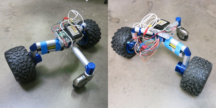
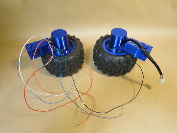
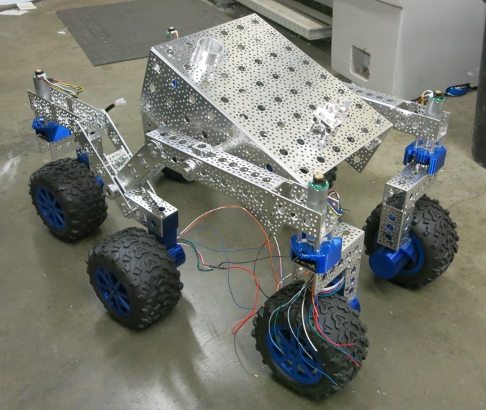
When our SGVHAK rover project started moving beyond individual units of our custom wheel gearbox design and towards a multiple wheel chassis, it was happening on both the hardware and software fronts. Our Flask-based control UI has worked well up to this point, allowing us to tune RoboClaw motor controller parameters to suit our wheel design. Building this first draft UI taught us a lot, and as we learned we also realized how it reflected our ignorance at the beginning of this project.

And so we bid goodbye to our first draft rover UI RogerPiBot to start a new project SGVHAK_Rover. This way we retain all the testing & tuning capabilities of the existing software, leaving that as-is. Freeing us to create a new user experience.

The major changes are:

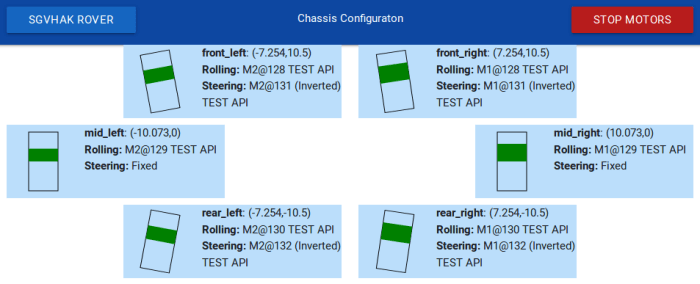
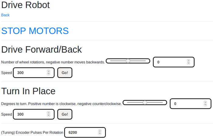
  1. Simple touch-friendly controls instead of HTML forms with a lot of fields. The form was a very powerful tool for tuning parameters from a desktop workstation, but we’re getting out of the engineering test phase. All interfaces will now be tailored towards operation from a small touchscreen.
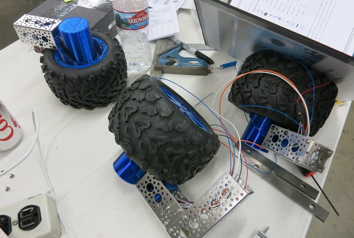
  2. Rover as a unit instead of wheel as a unit. We need to start treating all six travel motors and four steering motors aboard our chassis as a single unit, as the user expects the software to do. Target audience for this software will not be interested in poke and prod at motors individually.
  3. Configuration files instead of source code edits. The new software is built on the assumption that will be people who want to use it but is not familiar with Python or code in particular. Part of this meant configuration information will now be stored in human-readable JSON files at the root directory instead of asking people to go in and edit Python source code.

There were various other changes big and small. One of the larger changes was separate from the rover itself: we chose to switch away from using Bootstrap purely for the sake of HTML creation exercise. This time around we’re using a different library called Materialize to help create our responsive UI.

Unfriendly UI For Two Wheel Test Chassis

Our first attempt at rover software was a wonderfully informative hands-on adventure on creating a path from a cell phone’s web browser HTML all the way to serial bus commands sent to a RoboClaw motor controller. Fortunately or unfortunately, these lessons also put a finite lifespan to the software as we start to discover basic mistakes that we didn’t know we were making until we got a little smarter.

Before we leave the first draft behind, however, it had one final role to play. This point in software development timeline coincided with our rover wheel development’s completion. The actual six-wheeled rover chassis is still in the future, but our wheel development is mature enough for us to build a test chassis. Two wheel units were assembled and integrated into a bare-bones test chassis.

This chassis needed a brain and a controller.

To enable motor control via differential drive, we hacked together a minimal user interface for sending commands to our test chassis. Not much effort was spent on user-friendliness and its layout is very much an engineering number cruncher’s idea of an interface. (Also referred to as “bad UI.”) It was just enough to let us move the robot around and uncover some finishing issues in the wheel design, but not much more than that.

The robot moving under its own power attracted attention from other people in the work space. Naturally some asked if they could try driving the robot but one look at the interface and the response was “Um… maybe I’ll wait for a later version” and the phone was handed back.

No offense taken, it’s another vote in favor of moving on. We’ll close out the “RogerPiBot” project at this point and start a new rover control project incorporating all the lessons we’ve learned.

Raw Differential Drive

Basic Motor Test for SGVHAK Rover

Our first opportunity to deploy the new Bootstrap-based touch-friendly HTML UI was a basic but critical motor test. A RoboClaw motor controller utilizes encoder feedback to know what the motor is doing. Based on this feedback, logic within the controller adjusts its electrical output to deliver either a commanded velocity or a commanded position. For any of that to work, an encoder must be installed properly. Our rover’s travelling wheel motors incorporated a pair of LED+photo diode units as optical quadrature encoders. Since we have a pair of sensors, there are two possible ways to wire them to RoboClaw input: one of which is correct and other is backwards.

To verify wiring, we need a basic motor test that will instruct RoboClaw to drive its motor at some power level, which is something it can do without encoder input. Then the test will query for encoder count and verify positive motor motion increments encoder count. If positive motion decrements encoder count, we’ll need to swap some wires.

Which wires need swapping? That depends on which way our motor is turning. We want positive motor rotation to correspond to forward rover motion, which means the left and right sides of the rover will be wired in mirror image. For rover’s right side wheels, positive motion will be clockwise (when viewed from rover’s right) and rover left wheels will be counter-clockwise. This desire to see the wheel motion in context of rover chassis is why we wanted this motor test to be usable on board the rover itself via the Raspberry Pi touchscreen.

If positive motor motion is rotating in the direction we want, and we need to swap wires, then we swap the encoder wires to maintain motor direction. If we need to swap wires and our motor is spinning in the wrong direction, we leave the encoder wires alone and swap our motor control wires instead. If the direction is wrong, and encoder is in sync, we’ll need to swap both sets of wires.

Basic Motor Test

HTML UI work described in this post began with this commit visible on Github.

RoboClaw HTML UI Work Assisted By API Stub

It was great when RoboClaw control UI project picked up help from somebody who knew what they were doing with web design. But it exposed a problem: the code is dependent on an actual RoboClaw motor controller connected to the machine. This was fine when development work focused on how to talk to the controller and hear what it has to say in return. But now that we have a parallel track working on improving the UI appearance, the RoboClaw dependency is unnecessary.

import roboclaw_stubTo remove this dependency, we introduced a RoboClaw API stub which could stand in for a physical RoboClaw when iterating through UI work. To do this in languages like C++, we would have to declare implementation of an interface and write a body. This makes sense when we expect all implementations of an interface to have roughly equivalent levels of functionality. For a test stub like this, though, that is not true. We only needed the small subset necessary to allow development of the specific relevant UI component. In languages like C++ this means most of the interface implementation would be tedious fillers that do nothing but raise a “Not Implemented” error.

Fortunately we are working in Python, which does not have such rigorous enforcement of interface implementations. We could implement just the methods we actually need to unblock UI development, and stop. There’s no need to recreate everything and we could leave out all superfluous “Not Implemented” declarations.

This is one arena where “duck typing” works in our favor, letting us get away with skipping all formalities of statically typed languages. There are downsides to dynamic binding but today it is a win.

Make RoboClaw HTML Control UI Scale Across Different Screen Types with Bootstrap

The basic HTML UI we were using to learn how to work with a RoboClaw motion controller was bare-bones web 1.0 in style. This worked very well when it only had to let us experiment to understand the controller while it’s sitting on a test stand next to the development workstation computer.

Once we got ready to move beyond tethered desktop computer scenarios, though, we had a problem. We had two touchscreen scenarios: one for UI directly on the robot via the Raspberry Pi Foundation touchscreen, the second scenario is remote control using a cell phone or tablet’s web browser.

Because the UI content was written in bare HTML, it does not scale to touchscreen devices the way we expect all modern web sites to do. In order to make this happen, we had to bring our HTML from the relative stone ages to conform to current practices.

Fortunately, this project received help from someone who has recently completed training on web design and development. [Amy] volunteered to jump in and make the controller HTML presentable and usable on touchscreen devices. Thanks to the open source nature of the web, most of the hard work has already been done by others and we just need to pull in one of the many freely available libraries to help build an UI that can respond to changes in the web browser environment.

For this experiment, [Amy] pulled in Bootstrap then began retrofitting the control test UI so Bootstrap can perform its magic across the different types of screens.


Link in Bootstrap

Refining Motor Parameters Applicable to SGVHAK Rover

Once we had a basic HTML UI for tuning RoboClaw PID parameters, we started exploring remaining surface area of RoboClaw API. In the arena of motor control, we have three categories of motion to choose from:

  1. PWM or duty cycle: This is the most basic type of control, where the motor is given a particular amount of power regardless of its load. If the motor is unloaded, it turns faster. If there is load, the power level does not change so motor slows down (or stalls). Since the quadrature encoder is not involved in this mode, it is particularly useful when diagnosing problems and we want to eliminate encoder error as a potential problem. There’s also no PID turning required for this mode to work, so it is also useful when trying to verify whether a problem is caused by bad PID gains or not.
  2. Velocity: In this mode, quadrature encoder activity matters. RoboClaw monitors encoder pulses and adjusts motor power to maintain the commanded velocity. If there is load of the motor, its slowdown will be apparent via encoder pulses and RoboClaw adds power to maintain commanded velocity. And conversely, when motor load is reduced and it starts speeding up, RoboClaw will see this in the encoder pulses and cut power to maintain commanded velocity. This is the mode we’ll use to control the wheel motors’ rolling travel. It requires a properly functioning encoder, at a high enough resolution, plus reasonably tuned velocity PID parameters.
  3. RoverTestConfig

    Position: In this mode, RoboClaw is told to move to a specific position and hold there. If external forces move the motor off its commanded position, RoboClaw will increase power to return to position and hold there. We will be using this mode to command motors in charge of wheel steering angle. In addition to the encoder requirement and velocity PID, there is a second set of position PID and both sets need to be tuned for a particular configuration.

Getting our bearings with RoboClaw motor control, we would first explore a tuning API from the command line then incorporate it into our HTML-based UI so we could rapidly iterate through parameter values.

The many iterations of this exploratory and tuning adventure (including all the mis-steps along the way) are publicly visible on Github.

Web-Based RoboClaw Control For Test and Configuration

The first step in the journey to a HTML-based rover UI is to prove we can write something in Flask to allow a web browser to send command to a RoboClaw motion controller. The next step is to build something useful. Early on in SGVHAK rover project, that meant a technical tool to configure and test motor control parameters.

The goal of this tool is to simplify tasks done earlier via typing RoboClaw API commands into the interactive Python shell. As part of proving the browser interface concept, we’ll also try to make the interface usable from a touchscreen device. More point-and-click, less typing on a keyboard. We’re not putting too much effort into making the user experience pretty and polished, though. This is an engineering tuning and testing tool, not an end-user tool.

The advantages of using a web framework immediately paid off in the ease of building sets of motor controls. It allowed rapidly iterating through ideas to find the feature set that would be useful and discarding features that are not. There’s little wasted effort as we’re not worried about making things look good and are OK with primitive web 1.0 forms.

One downside is not the fault of a web framework, it is more a consequence of trying to fit a square peg in a round hole. Web apps are fundamentally focused on supporting large numbers of users, and here we’re really only concerned about controlling a single resource: the RoboClaw. Flask is built around some patterns intended to help developers write code that scales to high number of users & sessions. But in the context of this single-user, single-session usage, such patterns sometimes got in the way.

Another downside is a web-based interface inherits all the problems of the web. Inputs sent by a client is inherently untrustworthy and must be properly validated before processing. The web framework can help handle some of that with automatic protection of cross-site scripting attacks, but the developer is ultimately responsible for sanitizing the input before processing. In the context of an engineering tool with short expected useful life, it’s a problem we can set aside for now.

RoverTestConfig

The proof of concept code discussed in this blog post is available on GitHub: testconfig.py under https://github.com/Roger-random/RogerPiBot

SGVHAK Rover Control With Flask, a Web Server.

Recent blog posts outlined the hardware side of SGVHAK rover project, now we’ll rewind and tell the software side. The first drop of information for the SGVHAK rover team included only information on hardware, the baseline rover software was promised and yet to come. We didn’t think too much of it until the Microsoft Windows-based Ion Studio tool failed to auto-tune the PID parameters for our rover wheel.

The effort to debug rover wheel control led to the Python API released by Ion Motion Control to communicate with Roboclaw motion control board. As a platform-independent tool, Python was always the ultimate intent since our target platform for rover brain is a Raspberry Pi. The failure of Ion Studio just advanced the timeline.

The manual PID tuning session was done entirely in the Python interactive shell calling into the Python API, from updating PID values to commanding motor motion. While flexible and effective, all the typing became very repetitive very quickly.  Now that we’re past the first PID tuning work session, we have a decent idea what APIs are most useful for this project.

We didn’t set out to design a new rover UI, originally we just wanted to ease building the machine and tuning parameters. This nuts-and-bolts goal is why investigation started with a text-based system. An advantage of a simple command line based system is that it can be used wirelessly via SSH so that we won’t have to be tethered to the robot while we tune. This is why we started by looking into Python’s curses library to create text-based displays.

It didn’t take long, though, before ambitions grew. The ultimate UI for the rover won’t be text-based, why learn a whole new text UI framework just so we’d have to learn a graphical UI framework later? That thought was just the first step. The next step looked at Qt, which is a cross-platform GUI framework we already know to work across PC, Macintosh, and Pi. But wireless networked access to a Qt GUI takes some work. Far more than it would take to put up some HTML to be accessed over the network. So… why not do that instead?

That’s how we arrived at today’s investigation: for a simple rover UI, try using HTML. This allows us to have the exact same UI over the network as well as locally. (http://localhost) We’re learning something new anyway, and learning a Python web framework is more likely to be useful for future projects than learning a text UI framework. To kick off this effort, we ask two questions:

  1. What framework to use? There are a lot of different Python web frameworks running around on the internet. While learning Ruby on Rails, I came across references to its Python counterpart Django. They are both far heavier than we need for this project, though. A search for something more lightweight pointed to Flask, backed up by at least one Quora discussion.
  2. Does it work with Roboclaw API? It took a little fiddling with user groups to gain access to the USB serial port, but once that was done the answer is: Yes it does.

With a successful smoke test, we’re going ahead with building a HTML-based rover UI.

HelloFlask Success

SGVHAK Rover (and Predecessor) at SCaLE 16x

Friday, March 9th, 2018. SGVHAK Rover made its public debut on the exhibition floor of SCaLE 16x. It participated in the SGVLUG booth advertising the entire family of SGVLUG and related groups including SGVHAK. It was good to have a deadline to motivate progress on the rover project and it’s even better to have successfully met it.

We also inadvertently lived up to the “hack” part of the name with the corner steering servo hack on the front right wheel. It was not part of the plan but an amusing coincidence. Given that we still had the weak gearbox on the remaining three wheels, we weren’t very keen to hand control over to random visitors at the booth. We did run it around the floor and learned a few things about operating it in such an environment.

The most unpleasant aspect is the crowded RF spectrum. With so many booths filled to the brims with electronics, the wireless signal spectrum is just as crowded as the physical isles. Rover communication between the Raspberry Pi and the operator was occasionally unreliable and we frequently had to react to missed commands. Every page on the rover UI had a big red “Stop Motors” buttons and there were times we kept smashing that button continuously, desperately trying to get that command through, before the rover finally stopped. We’ll have to figure out a fix later.

On Saturday, the JPL team in charge of the baseline rover design stopped by SCaLE for their own public relations demonstration purposes. We had a brief few minutes where both rovers were running around side-by-side. It was fun to compare and contrast the places where two rovers differed, both intentionally and not.


SGVHAK Rover Steering Restored with Servo Hack

At the SGVHAK meet a week before SCaLE, the rover ran around for the first time in a public-facing configuration. It was a trial run to see how it would do, and we managed to expose a weakness in the corner steering motor gearbox. With a broken gearbox, the rover is crippled. We have the option to just drag the uncooperative wheel along, as JPL did for their Mars rover Spirit. (It’s even the same location: right-front wheel.) But since it is accessible on a workbench instead of on another planet, we should try to fix it.

Here were our thoughts on the motor:

The most obvious solution is to replace the broken unit with another identical unit, which we are not going to do because this gearbox has already proven itself to be too weak to handle the job. Instead, we’re going bigger: replace with a unit rated to handle more torque. This solution has a few concerns: the first is that it increases cost of rover design, the second is we still have nothing to absorb sharp shocks to the system. We can only “go bigger” for so long.

The third and most critical concern is time. We had wanted to demonstrate the rover running around at SCaLE 16x but the shipment of upgraded gearmotors won’t arrive in time. We need a short-term solution that we can build with what we have on hand, and the best candidate in the here-and-now parts pile are remote control hobby servos. Hacking a steering fix with servos serve two purposes: First, we hope it gives us a drivable rover by SCaLE. Second, it tests an idea that’s been kicked around.

Using remote control hobby servos to steer has the potential to reduce both rover parts count and cost. And devices called “servo savers” are an established solution from the remote control vehicle world to absorb sharp shocks to a steering the system. It’s something promising to investigate and, with a broken gearbox and a deadline, we have motivation to do so.

While I worked on the software modifications to support a steering servo, @mle_makes jumped into physical fabrication of a mounting bracket. Her resourceful fabrication using parts already on hand results in a jury-rigged servo mounting bracket that lets us steer the wheel until replacement motors show up. This configuration, with a servo handling one of the corner steering duty, was what we ran around at SCaLE and it worked really well. In fact, this corner survived the abuses of the weekend better than the others! With this hack’s success, we contemplate a future rover variant focused on servo motion.


SGVHAK Rover’s First (Brief) Drive Session

The SGVHAK rover team continued to work through problems and worked our way towards a first usable iteration of the rover. Wires are tidied up so there’s no risk of tangling up as the rover moves. All fasteners are tightened. The Raspberry Pi now runs as its own WiFi network access point and no longer dependent on an external wireless router. While there are many more items on the to-do list, these were the critical pieces to complete for public demonstration at SCaLE 16x.

Once it’s all buttoned up and powered up, we had what amounted to a very fancy and expensive remote-control vehicle. Unlike common toy remote control cars, this one can demonstrate the rocker-bogie suspension system used by Mars rovers. At this scale it is quite capable of climbing over people’s feet, sidewalk curbs, and decorative garden rocks.

Ginko driving

The controls were passed around to people who came to our SGVHAK meet just before SCaLE. This is a test to see how the rover handles drivers who weren’t involved in the build process. If this goes well, we can feel pretty confident about handing the controls over to anyone who wanted a turn.

The test, sadly, did not go well. We had been suspicious that the steering motors might not be strong enough to take little rover fender-benders, despite their advertised torque rating on paper. This confirmation was sadly confirmed in the form of a broken gearbox that ended the test drive session.

Test, find problems, fix them, repeat. This is not in itself a problem. But SCaLE is only a week away and stronger replacement gearbox+motor won’t arrive until afterwards. If we want to demonstrate the rover at SCaLE, we’ll need to get creative.

Chipped Tooth

SGVHAK Rover Systems Integration Test

It took some trudging through tedious nuts-and-bolts work (occasionally literally) before we got to our next milestone: the first system integration test.

  1. Structural – the rocker-bogie suspension system assembled and can accept all six wheels.
  2. Mechanical – All six wheel assemblies and all four steering assemblies ready to install on structure.
  3. Electrical – all five RoboClaw modules installed on the rover chassis, with wiring harnesses built to connect all motors to their respective RoboClaw.
  4. Communication – All five RoboClaw connected together into a single serial command network, connected to a USB-serial bridge that will talk to the brain. (Ubuntu PC, Raspberry Pi, MacBook, anything.)
  5. Software – Ready to talk to all five RoboClaw modules and sending commands for rover mobility.

The integration test was intended to help expose problems, and it was very effectively at doing so! Some highlights:

  1. While all RoboClaw were correctly configured for advanced packet serial command and on the correct baud rate, they weren’t all properly communicating because they haven’t all be set into multi-unit mode. Toggling multi-unit mode is not something that we could do with buttons on the RoboClaw so we had to hook up the individual modules to update configuration.
  2. The RoboClaw motor encoder A/B are reversed between the two channels on the board, which resulted in some of our wheels running in opposite direction than the encoder expected. This meant reversing some of the motor drive power wires in order for the motor direction to agree with encoder direction.
  3. The control software responded to input events as fast as it could, which far outpaced the RoboClaw communication resulting in a backlog of commands. This backlog overflowed some communication queues causing crashes.
    1. Long-term fix: The server needs to throttle event response. We settled on a maximum rate of an event once every 50ms.
    2. Short-term fix: Create an alternate UI that only sends one command at a time to avoid the crunch.

After we worked through the issues big and small, we could run the motors with the rover lying on its back. It won’t be long before we’ll be able to drive the rover on its own wheels.

WheelsRolling

Structure and Wiring Work Still To Be Done

Once the rover was standing on its own wheels, we knew the majority of structure work is behind us. Not that we were close to completion – there were lots of details to finish up before the structure can be declared done. And it would have been naive to believe that the structure will perform flawlessly once assembly is complete – there were many problems that need fixing.

Once the structure work started ramping down with frame assembly, many other robot work can begin with a far better idea of the actual structure we’re building around. For example, it didn’t make a lot of sense to build wiring until we knew where we have space to route those bundles. It started with prep work – cleaning up rats nests and terminating components in connectors to make assembly easier. Here’s a before-and-after comparison picture.

Wiring cleanup

For the wheels specifically, we had the goal of making every wheel assembly interchangeable. Keeping all the wiring schema consistent makes it easier and less confusing to build, and allows us to build extra wheels on hand for quick replacement as needed. The only foil to this plan are the tires we’re using: the thread pattern is directional and has a recommended turning direction. The tires should work sufficiently well in either direction, but for the first draft we’ll put in the effort to align the tread patterns for cosmetic purposes if nothing else.

Rover Standing On Its Own Wheels

While building a big project, it’s good to celebrate milestones when they roll around. Here’s a picture taken back when the team first assembled all the major pieces necessary for our SGVHAK rover to stand on its own wheels.

Rover on Wheels

It was cause for celebration even though there were still a lot of work to do: the wheels in the picture aren’t solidly attached yet. Posing for this picture required some careful handling to make sure they don’t fall off. The main body is basically just an empty bracket barely holding the two side assemblies together. Those two rocker-bogie assemblies still need the cross arm to connect them in order to create desired rover suspension kinematics. None of the electrical connections have been made – the wheels can’t roll on their own power nor steer. Even if they could, the software isn’t ready to drive them, either.

And we haven’t even looked at the LED display for the friendly face of the robot.

But even with wires dangling, it doesn’t look half bad. This was a pretty good morale boost for the team to see a recognizable shape coming together.

Making Rover Legs Stronger

One of the main objectives of SGVHAK rover build is to beta-test the instructions before it is opened to the world. Much of this involved feedback along the lines of “this part of the instruction is not clear” or “this part is the wrong part.” But we also occasionally send in feedback of “here’s a problem we see, and here’s the solution we came up with.” An example is the how the corner wheels bear their weight.

In JPL’s original build, the entire weight of the corner wheel comes through the shaft used to steer the corner wheel (highlighted in blue) pushing into the steering gear motor. Motors are typically designed to handle rotational stress and not force along the rotation axis pushing into the motor.

Steering Shaft

In the short-term, things will push against each other until the force makes its way to the gear motor outer casing, which will then push against the motor mount and eventually make its way back down to a structural member. But this long roundabout way will cause undue wear on the gearbox and certainly reduce its life.

So we offered a solution: Add a small piece of metal to take the weight off the steering shaft, transmitting it directly from the wheel assembly to the bearing block that looks like it should be strong enough to do the job. With this addition, the gear motor no longer has to worry about supporting the weight, it can focus on its job: steering the wheel.

We think this is a worthwhile addition to our rover. Unfortunately this spacer was cut on a lathe, which is not a piece of equipment most people have access to. If the authors agree this is a problem, and agree with the general idea of our solution, we’ll need to think up a variant of this fix that would be easier to make.

Spacer

Spacer installed

Rover Frame Assembly

The SGVHAK rover wheels were a deviation from JPL’s baseline design, hence that’s where we started to get an early lead on any problems. As the baseline design is already proven, that could start later. The point of this exercise is to beta test the build instructions and evaluate their clarity and accuracy. Given it is still an early draft, there was a lot of room for us to offer suggestion for improvement. Sometimes the instructions alone left us bewildered, and we ended up going to the CAD file to see how pieces were intended to fit together. It helps, but the fact is we still have ambiguities that might cause problems down the line. The joy of being pioneering guinea pigs! Minor difficulties aside, the main metal frame is coming together mostly matching what the instructions dictated.

Frame Assembly Underway

Since we’re doing our own wheels via 3D printing, we had to figure out where our changes blend in to the original design. Here are the wheel assemblies while we iterate on the integration.

Wheel Assembly Underway

The aluminum U-channel are pretty easy to work with and turned out to be far stronger than the expectation formed by looking at pictures. This should be one sturdy rover. The U-channels are also really easy to work with, for the most part roughly similar to IKEA furniture assembly. However, there were a few parts that needed more extensive work. Some of this work proved to be challenging. We needed a few short segments of aluminum rod with holes drilled through them. Even with the help of a vise clamping the rod on the work table of a drill press, movement crept in. The first attempt was not usable, it took a few tries to figure out the necessary technique.

Staying Centered is Hard

Adventures in Manually Tuning RoboClaw PID

Encoder Wheel Upgrade
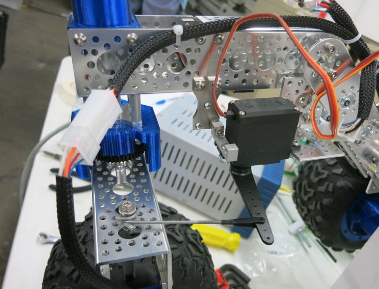
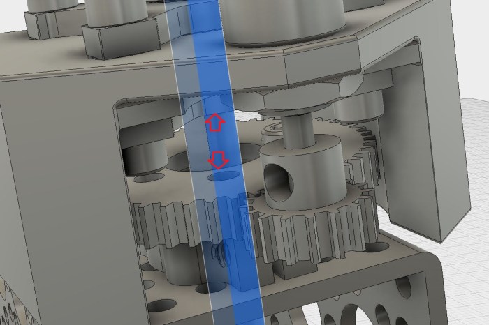
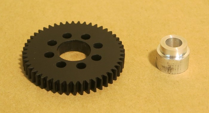
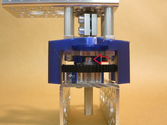
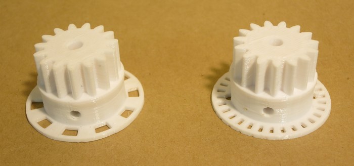
Increasing the gear lash improved performance tremendously, but still a little short of where we need to be. In an effort to improve motor control, the 3D-printed encoder wheel in our planetary gear wheel hub had its resolution tripled. This triples the number of quadrature pulses sent to our RoboClaw motor controller board, and we hoped that will enable smoother behavior. The hypothesis: with triple the pulse frequency, RoboClaw can detect changes in one-third the time and start responding faster to changes. The hypothesis was proven correct but it took a bit of work to get there.

We had to figure out how to configure the RoboClaw to correspond to the change. The most obvious parameter to update was to triple QPPS (quadrature pulses per second) to match the triple resolution. Tripling the encoder resolution unfortunately hasn’t solved our inability to use Ion Studio’s auto PID tuning algorithm (it still freezes up) so we had to return to manual tuning.

Armed with theory of PID but not details of Ion Motion Control’s implementation, we started adjusting the Position PID values and sending motor positioning commands to see their effects. First we tried tripling them, then cutting them by two-thirds, neither resulted in good response. Eventually we remembered some earlier indications that the Velocity PID seemed to have some involvement in position commands, even if we weren’t using the motor velocity commands. The Position PID values were restored to what worked before, and we start playing with the Velocity PID.

Tripling all the Velocity PID values were not fruitful, but cutting them by two-thirds felt like we were on the right track. We ended up with velocity P roughly 25% of what it was before, the I at 10% of its previous value, and D remained the same. There’s still a lot of tuning work ahead of us but this got us in the ballpark with a motor that behaves close enough to what we want.

Lessons learned:

  • The Velocity PID values are not used only for motor velocity commands. They affect the behavior of motor position commands as well.
  • When increasing resolution for an encoder attached to a RoboClaw, leave the position PID alone and start with decreasing velocity PID values by corresponding ratio.

Spring 2018 Brewery Art Walk

This weekend’s Brewery Art Walk was my first visit to the facility. I arrived to find a larger than expected campus of artist lofts, roughly half of which were open for event visitors. I aimed to find artworks that are beyond the typical flat two-dimension works so in the interest of time I skipped most studios of painters and photographers.

The reason I even knew about the event was because a member of Two Bit Circus advertised the event (and their participation in it) during lightning talk segment of Hackaday LA’s March meet. So my first stop was the exhibit room for Two Bit Circus.

Their subtitle was “Engineering Entertainment” and all exhibits certainly fit the bill. Here’s one installation called the Ledge, where the customer dons an Oculus Rift headset showing footage of riding a window-cleaner’s platform up the side of a high-rise building. The illusion is enhanced by the platform, which was motorized to give a wobbly sensation. As far as I can determine the wobbling pattern is fixed and has no correlation to the visual motion but it is still cool.

Two Bit Circus - Ledge

I had hoped to get a view of the workshop area as well, but that was not open for visitors. All we got to see was the nifty entrance. The hand crank to the right of the door turns the gears and chains of the sign over the doorway.

Two Bit Circus - Workshop

Facing this door is a cellular radio tower wearing a palm tree disguise.

Cell tower palm tree

Walking into the loft of Dystopian Studios will transport you into a space fully implementing the aesthetic of a dystopian future. The space itself was as much a work as the individual pieces on display. The area which caught my attention was a collection of Nerf guns (some of which overlap with my collection) modified to fit with the Dystopian Studio theme.

Dystopian Studios Nerf.jpg

On the theme of artists applying their art to their space, Bruce Gray‘s studio was not open for visitors but there was enough visible for me to see he’s given his air compressor the Charlie Brown treatment.

Bruce Gray air compressor

One of the studios had a machine outside blowing soap bubbles filled with smoke. The space appears to be full of clothing creations. Personally I would have found it far more interesting if the whole space were dedicated to novel mechanical contraptions like smoke bubble machines.

Smoke Bubbles

I had expected to find a few kinetic art studios and was not disappointed when I found William Sandell’s Kinetic Assemblage.

William Sandell Kinetic Assemblage

On a larger scale, Richard Wilks studio had a few items on display. Inside the studio is a work in progress making a spinning metallic sculpture that aims to evoke the fluid motion of a jellyfish. The white wheel on the right is a prototype for visualizing motion before they are built out of metal.

Richard Wilks jellyfish

Parked outside their studio entrance is the Aquatrope. It is the type of work I expect to find at Burning Man and several pictures shown adjacent to the piece imply that’s exactly where it has gone.

Richard Wilks Aquatrope

The highlight of today’s visit was finding Sean Sobczak’s Sandman Creations studio. These sculptures made of welded segments of wire is an impressive level of sculpting beyond working in solid media. It’s not simply a wire mesh like the 3D data in a computer: the wires serve an aesthetic purpose in addition to their structural requirement. Sometimes they trace out surface features of the subject, sometimes they flow and move on their own path.

Sobczak Sandman Creations dreams

Many of the pieces on display feature strings of lights inside the skeleton and a fabric wrapping the metal on the outside.

Sobczak Sandman Creations octopus

Sadly photographs do not do these pieces justice, so full appreciation requires enjoying the work in person. Which I plan to do again in about six months! (Assuming the studio is open for Fall 2018 Brewery Artwalk.)


Tiny Increase In Wheel Hub Gear Lash Gave Huge Increase In Usability

After initial tests of the first two wheels, we have enough information to think our 3D printed gears are meshing too tightly. They are catching on each other which briefly require more motor power to continue rotating. This occasional spikes of power is making it difficult for our motor controller to keep speed steady and predictable.

To resolve this, a new set of gears have been 3D-printed with a slightly larger gap (gear lash) between them. The initial gears were printed with 0.3mm which was enough to compensate for imperfection inherent in hobbyist level 3D printers. This allowed assembly and start them turning, but as we found out, not smoothly. The latest gears were printed with the parameter set to 0.5mm. This will give up some precision, but we hope to get more predictable operation in return.

When the new gears were assembled, the smoother movement was immediately obvious. It ran better straight out of the 3D printer than the old tighter gears ever did. Even when the old gears were lubricated and had some time to wear in. As expected, there was greater slop to go along with this change. Rotating the wheel by hand implied the rover might rock back and forth about 1-2 mm within this gap, roughly as much as what we’d expect to be absorbed by the rubber tires. The precision has indeed decreased, but probably not enough to affect driving dynamics.

We hooked the new gearbox up to the RoboClaw motor controller to try Ion Studio’s automatic PID tuning again. We hoped the old gearbox’s unpredictable motion was why the software froze up trying to auto tune. Sadly the software still froze up and auto-tuning remains out of reach. However, the good news is that the smoother motion made manual PID tuning much easier and we’ve obtained some decent values to use as starting point. (RoboClaw position P=2400, I=0, D=1500, Deadzone=1)

We now have a wheel motor that can start turning reliably and smoothly, hold speed within an acceptable range, and decelerate to stop at a specified position. This was a hit-and-miss proposition with the old gears but the new gears make it look easy. Here’s a short clip showing the new wheel executing command to make one complete revolution and stop exactly where it started. No hesitation, no oscillation. Good stuff!

Wheel-Rotation

Test Chassis With Two Wheel Differential Drive

The rover didn’t always have six wheels. Since we were building our own wheel design, we wanted to make sure it works before we build six of them. Here was our first integration test chassis: putting the first two wheel assemblies together with a castor wheel.  It proved to be informative to see how the components work together before we got too much further into the project.

The first work session was marred by a minor miscommunication about the Raspberry Pi intended to be used as the brain of the chassis. As a short-term substitute, a small and light (and old) Dell laptop was taped on to the chassis to obtain some initial data.

Test Chassis with Dell

We could drive the test chassis around, but gearbox friction continues to be a problem. We had hoped the real physical load would add some momentum and inertia to the system and smooth things out. This didn’t pan out and we frequently encounter jerky motion of the robot. Our RoboClaw was constantly fighting to keep the motion smooth as it ramped the power up and down to grind through rough spots in the gearbox.

At this point the test chassis has been the focus of two work sessions. The second round included the Raspberry Pi that was originally intended. The motor motion, unfortunately, remained rough. The next effort will try to increase gear lash in the planetary gearbox. We’ll end up with more backlash in the system, something that might be problematic when it is compounded across six wheels, but nevertheless we hope it will prove to be a good trade-off.

Test Chassis with Pi