A common error when setting up a 3D printer is putting motor control parameters that don’t actually match the installed physical hardware. Sometimes this is glaringly obvious: maybe the X-axis moves 5mm when it should move 10mm. Big errors are easy to find and fix, but the little “off by 0.5%” errors are tough to track down.
In this category, a specific class of errors are specific to the Z-axis. When X- and Y-axis are moving around printing a layer, the Z-axis needs to hold still for a consistent print. And when it’s time to print another layer, the Z-axis needs to move a precise and consistent amount for every layer. This is usually not a problem for stepper motors typical of hobby level 3D printer Z-axis control, as long as the layers correspond to an even number of steps.
When the layers don’t map cleanly to a number of steps, the Z-axis motor might attempt to hold position in between steps. This is fundamentally a difficult task for a stepper motor and its controller, rarely successful, so most control boards round off to the nearest step instead. This rounding tends to cause periodic errors in the print as the Z-axis rounds a tiny bit higher or lower than the desired position, and failing to meet the “precise and consistent” requirement for a proper print.
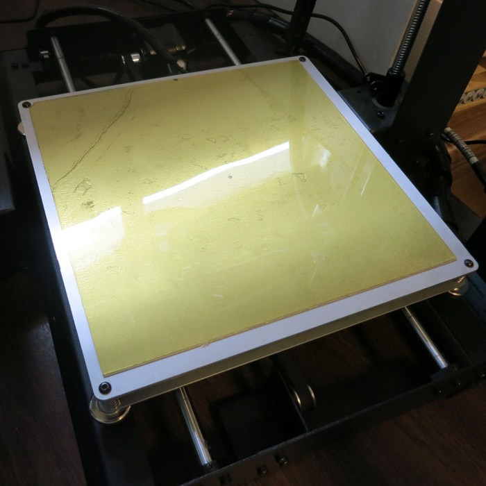
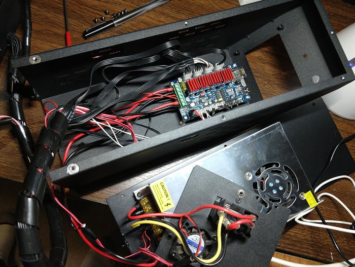
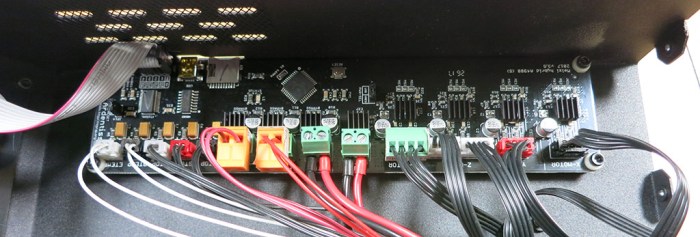
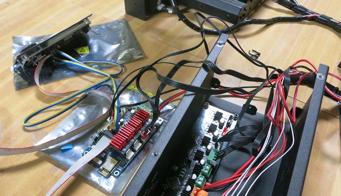
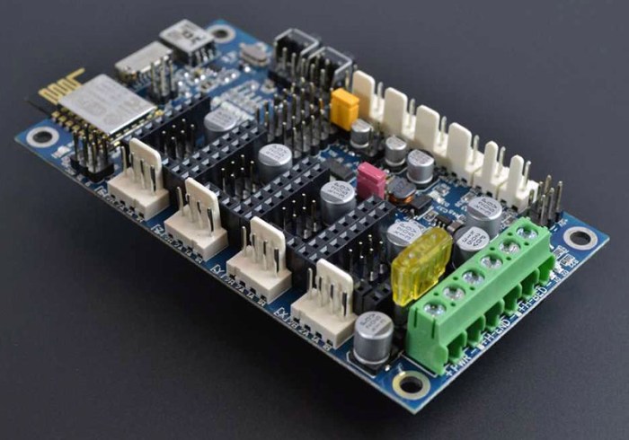
With a freshly configured Azteeg X5 Mini WiFi control board in my open-box Monoprice Maker Select printer, seeing a periodic error along the Z-axis when printing Sawppy’s wheels immediately placed suspicion on Z-axis motor configuration.
Back to hardware measurement I go, and reviewing motor control parameters. After over an hour of looking for problems in Z-axis configuration I came up empty-handed.
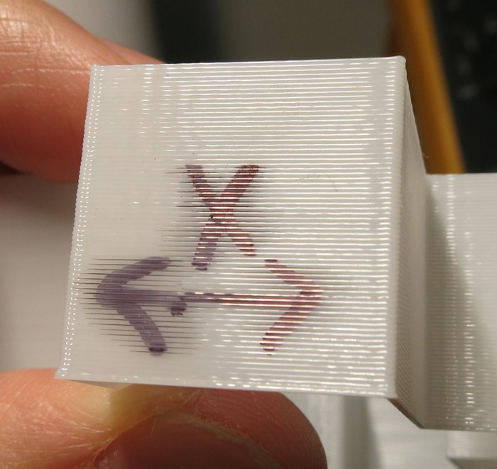
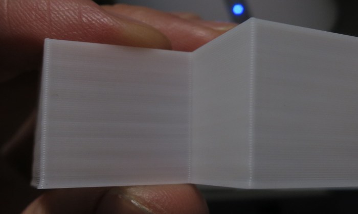
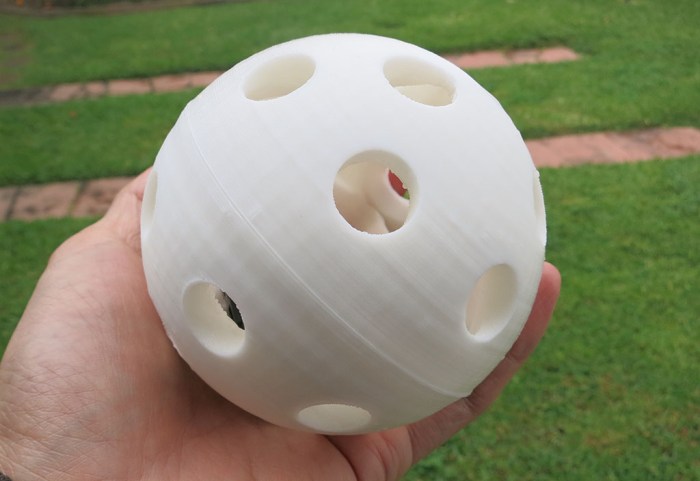
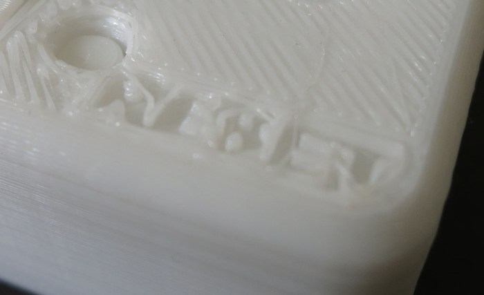
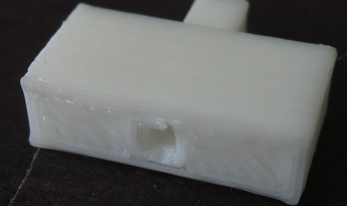
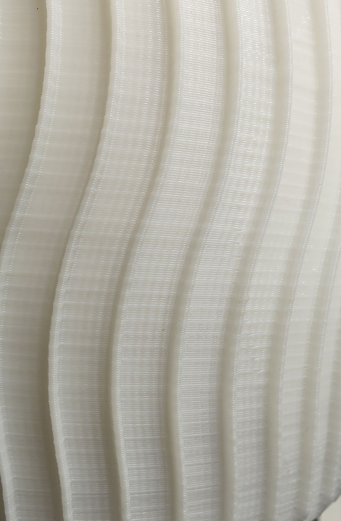
Then a key observation when looking at details under magnification: the error is occurring every 6 layers, and not at a consistent location all around the print. This little bump is actually in a spiral shape around the wheel, which would not be the case when rounding off Z-axis steps.
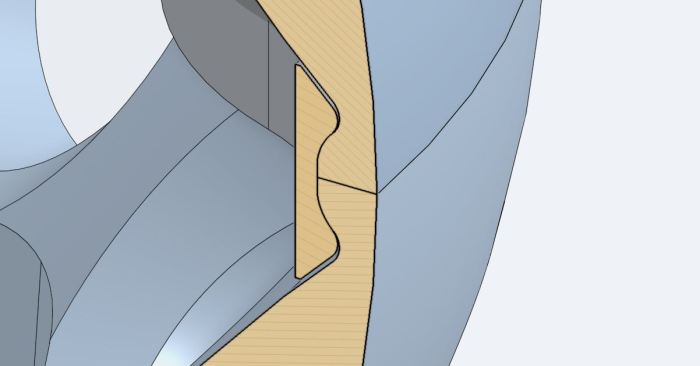
Following this insight, I went to review the 3D priner G-Code file and saw the print path is on a regular cycle printing the six spokes of the wheel. It printed the same way between 5 of those spokes, but the sixth is slightly different and that slightly different behavior cycles through the six spokes as the print rises through each layer.
It turns out this print artifact is not a Z-axis configuration issue at all, but the result of inconsistent extrusion. When moving in one pattern (5 of the spokes) it extrudes a certain amount, when moving in another (the final spoke) it ends up putting a tiny bit of extra plastic on the print, causing the artifact.


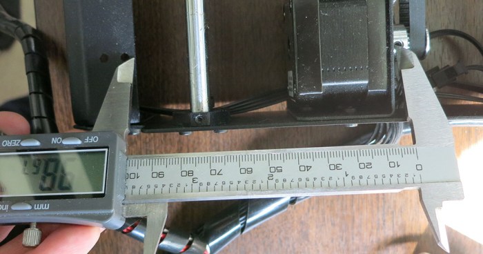
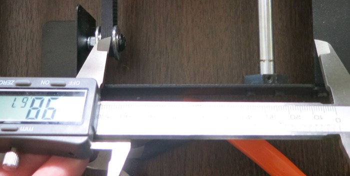 Without moving the caliper, I compared that distance with the equivalent in the back, between the chassis and the drive pulley mounted on the Y-axis motor shaft. We’re off by more than the width of the belt.