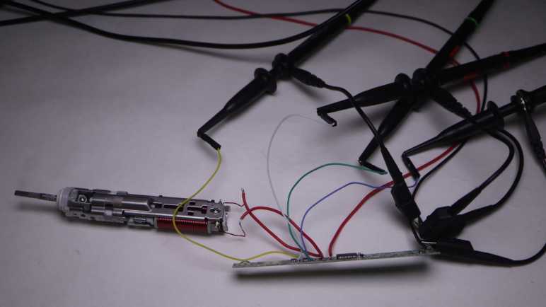
As a KiCad practice exercise and for a better understanding of modules I use in my projects, I wanted to trace through circuitry of this voltage step-down converter (a.k.a. buck converter) module. Unfortunately, it packed its components too tightly for me to easily see copper traces on this circuit board.
Now I could trace through all the paths, taking notes as I went.
I learned a new lesson about markings on surface-mount resistors. When the third character is a letter, it is an EIA-96 code and I need a decoder like this one on DigiKey to decipher their nominal resistance.
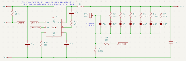
There’s no room for component labels on this tightly-packed module, so I assigned my own.
And here’s the KiCad schematic I generated from my tracing notes. Aside from the row of voltage pre-select resistors, it is superficially similar to the MP1584 module which is no surprise given they serve the same purpose. The most curious difference for me is the lack of a diode in this module. I had thought that was a required part of voltage conversion. Either I misunderstand or an equivalent is built in to this unidentified AELH chip.
Another surprise was the potentiometer only go up to 40k Ohms. Judging by the row of pre-select resistors, this implied the potentiometer is only be good for up to a little over 5V. If we want to go any higher, we’d need to use the pre-populated resistors for 9V or 12V, or figure out something on our own.
After a brief detour playing with AI-powered image generators, I returned to the challenge of deciphering the workings of voltage step-down converter (a.k.a. buck converter) modules I bought off Amazon(*), built around a chip I can only identify by its marking “AELH”. Not only is the identity of the chip is still a mystery for now, tracing through the surrounding circuitry is really hard due to the fact whoever laid out this circuit board was very efficient at packing everything into a small space and left very little room for me to tease out circuit traces.
It’s possible to see a difference between areas with and without copper, but it’s not a very clear difference. I tried polarizing filters but they didn’t help in this case. I also tried playing with contrast settings in a photo editor, which has partial success but still not clear enough.
The difference is much more visible on the back side (flipped here so all the vias line up between these two pictures) where it lacks shadows cast by various components. One defining characteristic of copper traces on a circuit board is that it is completely opaque, relative to partially translucent areas where we have just green solder mask over circuit board substrate without copper. Because the backside is generously covered with copper, shining light from the back won’t help me see traces on the front because the light will be blocked.
So I thought I would try shining light into the circuit board substrate from the edges. Looking in my pile of parts for a sharply focused light source, I dug up my pack of red LEDs with a tight beam pattern. (*) These were intended for use as “laser” pointers while being much cheaper than real lasers, and I bought them for my Lissajous curve project.
The results showed promise but clearly not enough. The advantage of these modules is their tight focus, not their power output. Once I shine that light into a circuit board, their light energy scattered as expected. Unfortunately it just didn’t pump in enough light to bring out much detail. I turned off all the room lights and turned up camera sensitivity, but it was not enough.
If raw power is more important than precise direction, maybe all I need is a bright LED. The easiest one to try is the “flashlight” feature on my phone sitting close by. I already had the AELH buck converter module in my Stickvise (*), sitting on a breadboard to bring it up to the right height for my camera lens. By coincidence, this was also the right height to line it up with my phone LED making the experiment easy.
We have a winner! The white LED set the circuit board substrate aglow, showing all copper traces as clearly visible dark paths. The effect is most pronounced on the left side and contrast quickly falls off towards the right, but for this module I only needed help on the left. If I need to apply this technique on a larger circuit board in the future I will probably need to build a rig to shine white LEDs from multiple directions, but for today my phone LED illumination was enough to trace through this circuit and draw up a schematic.
(*) Disclosure: As an Amazon Associate I earn from qualifying purchases.
In the short time we’ve had usable generative AI systems, they’ve quickly evolved from “obviously nonsense but there is an outline of an idea” to “superficially fine but nonsense beyond the surface”. Asking an image generator to design a rover has improved from a jumble of pixels to something that looks superficially like a machine but upon closer inspection couldn’t possibly work. These systems are evolving rapidly, so I’ll check back in a few months to see what progress they’ve made.
In the meantime, today’s systems may be usable if I ignore mechanical functionality and focus on appearance. For this second round, I’m asking Microsoft Bing Image Creator (powered by OpenAI DALL-E) to design a cute mascot for the Sawppy project, hoping for something like the mascot for the Mars 2020 rover naming contest. I gave it the prompt:
Mars rover with a rectangular smiling head and six wheels holding a sign that says “Build Your Own Rover!” in hand-drawn cartoon style on a white background.
And here are the results:
Contestant #1 comes across as a little creepy because it seems to have two faces: one in front of the body and another on top of the mast. It’s got only four wheels instead of the six I asked for.
Contestant #2 at least has only a single face, and a friendlier-looking one, but again it has only four wheels and the suspension linkages are missing entirely leaving the body to float in midair. Mars has gravity so this won’t work. The sign also skipped the word “own” for some reason, though if that was the only flaw, it’s something easily fixable in a photo editor.
Contestant #3 has a single face and a sign with all the words. Still only four wheels, but at least they’re connected with mechanical-looking linkages instead of a cartoon arc or missing entirely.
The good news with contestant #4 is that it has more than four wheels. The bad news is that it has five. I guess the AI judged this to be a fair compromise between four and six wheels? Only three of these wheels have visible suspension linkages, and they’re connected to the outside of the wheel instead of the center. Perhaps the AI had landing struts and pads in mind, and mistakenly thought replacing the pads with wheels would work equally well. An additional data point is that “five wheels” and “attached to tires” problems also came up for another rover design drawn as a result of Quinn Morley’s prompt. (See yesterday’s post.) This is not an accident… something in DALL-E is intentionally doing this, but why?
I was going to critique this entry for lacking a smile, until I noticed there are little arcs on the front of the body. That’s the wrong distance from the eyes on top of the mast to be a smiling face, but I guess it was satisfactory for an AI “does it have a smiling mouth Yes/No” checklist.
Looking at these as a group, I noticed they’re all drawn at the same three-quarter view angle in an orthographic projection with almost no perspective distortion. (Head of #3 and maybe #1 had perspective sides.) That was not part of my prompt and I’m curious if that is typical of “hand-drawn cartoon style”.
I like telling the generative engine to draw in cartoon style because it reduces a lot of visual noise and mitigates the uncanny valley effect of generators getting little details wrong. I think I’ll start with “cartoon style” for my image generator sessions unless I have a reason otherwise.
I also noticed all of these rovers have a boxy body on top of wheels and a boxy head on top of a mast, so it understood that much of the robots sent to Mars. But its training set must be dominated by vehicles on Earth, or at least that’s my hypothesis for its obsession with four wheels instead of the six I asked for.
None of these images are good enough to be the new Sawppy project mascot, but they’re very close. I’ll try again later. Bing beat Google to the punch on this one, but Google is working on an answer. Adobe also has a limited free tier for their Adobe Firefly product. I’m confident there will be more options in a few months. This was a fun distraction and good enough to let my brain think up a solution to my recent circuit board analysis problem.
Taking a break from exploring electronics, I went to the to-do list and picked off the item “look into generative AI”. This particular story started several years ago when GitHub user @johndpope opened a GitHub issue on my Sawppy repository advocating for a Lexan body shell. Aesthetics is not my focus for Sawppy but I’m glad to see others are thinking about cosmetic enhancements. In a recent update, @johndpope added a large number of images generated by Stable Diffusion. They’re really… something. If there’s potential here, I really have to squint to see them. For the most part these images generated by Stable Diffusion were not mechanically sound. Or even mechanically feasible. Or even sane. It’s a patchwork of bits I recognize, assembled into a surrealistic dream that reminds me of Salvador Dali paintings.
(Image credit: Stable Diffusion from @johndpope prompt)
What’s going on here? An Ars Technica article about Stable Diffusion running on Apple Silicon had put a note in the back of my mind, and after seeing @johndpope updates I thought I would look into it further. I do own an Apple MacBook Air with a M1 Apple Silicon processor appropriate for the links in that Ars Technica article, but it is my understanding my gaming PC’s NVIDIA RTX 2070 GPU would be faster still. So I followed instructions on this @AUTOMATIC1111 GitHub repository to run Stable Diffusion locally on my machine.
My experiment results were no better than what @johndpope had posted. Jumbles of things, nothing very coherent, and the occasional misshapen nightmare fuel. Other tools like Midjourney and OpenAI’s DALL-E were supposed to be better, but they were commercial offerings not available for running locally and I didn’t feel like this experiment was worth handing over my credit card. Then I read Microsoft had licensed DALL-E for Bing Image Creator. No credit card necessary, just a Microsoft account. Well, I have that!
To see if things have gotten better, I headed over and here’s the most sane result from the prompt: “mechanical diagram of a six-wheel mars rover in blueprint style“
(Image credit: Bing Image Creator from my prompt)
This is better looking than what I got out of local Stable Diffusion. (And ironically less Dali-like, given the DALL-E name.) But it is clearly weak on sound mechanical design concepts starting with the fact I asked for six wheels and got only four. Symmetry is not a well understood concept, either, as these four wheels are visibly misaligned relative to each other along orthographic axes. And there are random parts scattered around, what’s up with that? And finally, it seemed to have ignored the “Mars” part of my prompt as this creation shows no indication of adaptations for a Martian operating environment.
I tried a few variations on my prompt and my impression of this tool is to lean into its tendency for mechanical nonsense and get designs packed with greeble, because it’s certainly got plenty of visual noise. But I certainly can’t use it for anything that can function mechanically. To be fair, mechanical design is not the focus of such image generators. Plus, this field is still evolving rapidly so in a few months things might be very different. But at least for today, image generation AI pose no threat to mechanical engineering jobs.
A short while later I got another idea: instead of trying to make it do something mechanical, how about an abstract cartoon rover mascot?
[UPDATE]: In the comments, Quinn Morley got an interesting looking rover from the prompt “SAWPPY the rover, with six wheels and a body made of glass instead of metal, on Mars.“
(Image credit: Bing Image Creator from Quinn Morley’s prompt)
At first glance, this looks really good!
But upon closer inspection, I noticed the suspension linkages are attached to tires instead of hubs, and there seem to be only five wheels instead of the six specified. Something about this particular combination of flaws is appealing to DALL-E’s inscrutable brain because it also showed up in my cartoon mascot experiment.
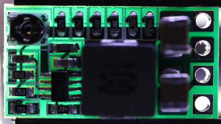
I’ve used a commodity voltage step-down converter (a.k.a. buck converter) module built around a MP1584 chip for many projects and it has worked well. Tracing the MP1584 module out to a KiCad schematic gave me a better understanding of that black box. It didn’t expose the enable pin, though, and there was one project where I wanted that capability so I tried a different buck converter module because it had an exposed enable pin. Here are pictures of the module, with the backside image flipped so all the traces and vias would line up as I try to follow them from one layer to another.
It had a row of resistors on board for voltage presets, and I could use them by cutting the trace to the adjustable potentiometer and soldering a bridge across the desired position. Despite the space dedicated to these preset resistors, this module was only about 60% of the size of the MP1584 module I had been using. Here they are side-by-side, with the MP1584 module to the left and this module to the right.
I thought it might be fun to decipher the magic behind this compact and capable module, but there were two significant problems.
The first was that I still couldn’t find any information on the chip at the heart of this module. I can read the marking AELH easily enough, but I only found one chip with that marking and it’s the wrong chip: the MAX6514UKP115, part of Analog Devices MAX6514 line of temperature switch chips. A temperature switch is not a voltage converter, plus I have 8 pins here and a MAX6514 has just 5-pins.
The second problem was the fact this module has a very tightly packed layout. The copper wiring on this circuit board are hard to see as they snake between tight gaps in components and underneath them in many cases. To trace through this module, I would have to somehow make copper paths show up clearly against non-copper areas of this circuit board.
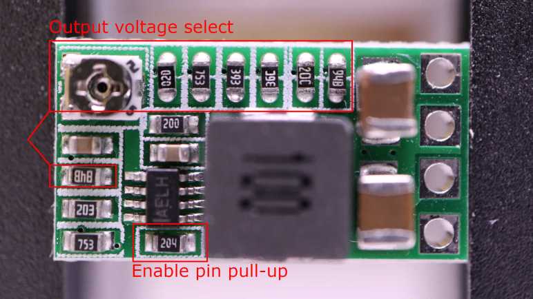
As a consolation prize I have at least obtained some practical data points on this module by probing with a continuity meter to see which pads are connected. Aligned with the voltage select solder bridge pads are a row of resistors lined up with the potentiometer. These form half of the voltage divider providing feedback to the AELH chip. I also found the resistor acting as the bottom half of the voltage divider.
An earlier project using this module had problem controlling the enable pin on this module because it would be enabled by default via a pull-up resistor. When my microcontroller went to sleep I wanted the boost converter to be disabled as well, but the pull-up resistor foiled that plan. Not wanting to deal with tiny surface mount components at the time, I decided to wire in an external pull-down resistor to fight that pull-up resistor. In the future, if I have a similar need, I have now located the pull-up resistor I need to remove.
For the moment, poor visual contrast of copper and its tight layout foiled my goal of tracing through this board to generate a schematic. As a change of pace, I took a break and went to play with AI image generators.
For the 4056 schematic exercise, I started on my own then checked my answer against others I found online. I’ll go a different route this time, because the components on this module are not labeled. It’s a minor thing but I want consistent component labels (R1, R2, etc) between my exercise and the answer key, so I’ll start by comparing the module against “typical application” schematic in the datasheet and label matching components with the same name.
I flipped the back side image so traces and vias would line up as I compare these two pictures.
I knew there would be some differences between this module and the “typical application” circuit, because it has a potentiometer to adjust the output voltage whereas the datasheet sample schematic had no such adjustment provision.
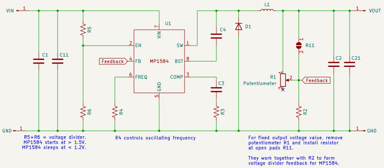
Here’s what I came up with. The potentiometer replaced resistor R1 in the datasheet schematic, acting as the upper half of a voltage divider that provides a feedback signal for the MP1584. Interestingly, this module preserved an option for fixed output by with open pads ready for a small surface-mount resistor. I labeled this pad R11. To convert this module to fixed output, we can unsolder the potentiometer and solder something in R11.
Resistors R5 and R6 formed another voltage divider, whose output level will dictate whether the MP1584 is enabled and running (>1.5V) or go to low power sleep (<1.2V) I found these earlier in an attempt to raise the enable voltage level. This schematic exercise confirmed my earlier understanding was correct and provided context relative to the rest of the module.
Capacitor C6 in the datasheet schematic was part of the COMP (control loop frequency compensation) circuit, but it was omitted on this module leaving just its friends C3 and R3 to do the job. I don’t understand enough to know why this is OK. Or if it’s not OK, what the consequences might be.
It’s probably not dropping capacitors for the sake of reducing component count, because the module actually added two capacitors not on the datasheet sample schematic: one each to help buffer input and output voltage. The small C11 is electrically parallel to the larger C1 buffering between VIN and GND. And a small C21 is electrically parallel to the larger C2 between VOUT and GND. It’s possible these capacitors needed to be close to something. If not, using different capacitors help smooth out response across the frequency range. In the intended use where MP1584 is part of a known circuit, specific frequency response can be planned for. But since this is a module that may be connected to different circuits, compatibility across a broader range makes sense.
One detail I found interesting was the BST (bootstrap) pin, which the datasheet explained is part of the power supply circuit for the high-side MOSFET driver. That seems reasonable except it is supposed to be connected to SW (switch) via a capacitor. SW is the output signal for the high-side switch. How is that high-side MOSFET powered by its own output? There must be something interesting going on with the startup behavior of this pin. Is it typical of buck converters? I can look at another one to compare.
After drawing up schematics of circuit boards salvaged from hair clippers for KiCad schematic practice, I decided to increase the difficulty with a single cell lithium-ion battery management system (BMS) module built around a 4056 chip. Since this is a popular module made by many vendors, I know publicly available schematics already exist. I don’t see my KiCad exercise as duplicate effort. I see those existing schematics as an answer key for me to check against!
In my earlier look, I found many chips from different vendors under the 4056 designation, all of which seem to be mostly compatible with each other. Since then, I’ve come across several pointers to NanJing Top Power’s TP4056. Either they were the first or they have been the most successful vendor of this solution. The modules I have on hand are not genuine TP4056, but one of the competitors marked 4056H.
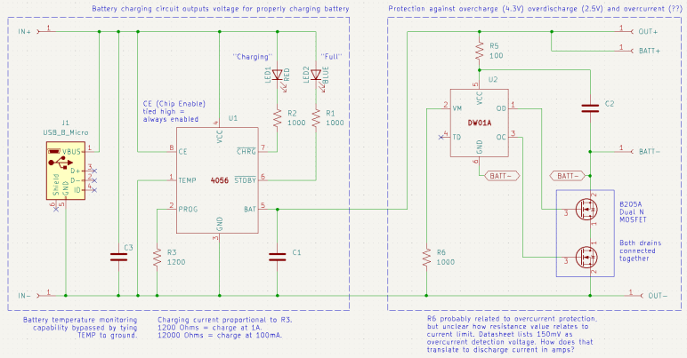
I was also unable to read any markings on component marked U2 before. Thanks to my new polarized light macro photography solution, I could now make out its faint markings as DW01A. This is a battery protection chip that guards against over-charging (cut off at 4.3V), over-discharge (cut off at 2.5V) and over-current (150mV? That doesn’t make sense.)
Armed with this information, I drew up my own schematic symbols for the 4056 chip and the DW01A. They’re probably available in a KiCad part library somewhere, but I wanted the practice with KiCad symbol editor. It took me a while to figure out how to label inverted pins. Eventually I found this KiCad forum thread telling me to put the name inside curly brackets and prefixed by tilde. So for the inverted STDBY pin I had to type in ~{STDBY}.
I ran into an ambiguity with surface-mount resistors on this board. There were several labeled with 102 (meaning 1K Ohm) or if I should read them upside-down as 201 (meaning 200 Ohm). In this case I was able to measure them at 1K Ohm but I won’t always have that luxury. How to I figure out which way is up?
I drew my schematic with dotted lines marking the two major feature areas: to the left is the battery-charging circuit driven by the 4056 chip, to the right is the battery-protection circuit under control of the DW01A chip. I traced through most of the 4056 side earlier, because I was looking to adjust charging rate and found I could do so by replacing R3 with resistor of a different value. This time I was more curious about the over-current protection side of the module. Looking at my schematic, I thought R6 would be a promising lead for current control, but at 1000 Ohms its resistance was far too high to be a current-sensing shunt resistor. Plus, it wasn’t in line with the load path. I didn’t understand how it could work or how it related to the 150mV current-sensing value listed in the DW01A data sheet.
Thinking I probably made a mistake in my schematic, I went online to check against others and it seems to match. One of those schematics was attached to this Electronics StackExchange thread, which also explained how over current protection works in this design. The details are a bit over my head, but supposedly works through the dual N-channel MOSFETs already present to handle over-charging and over-discharging. Sounds like the engineers behind DW01A were clever enough to get over-current protection without using a current-sensing shunt resistor, and that’s why I couldn’t find one. This is very interesting and I wished I was familiar enough with these components to fully understand how it works. Maybe I can come return to this topic later after I’ve learned more electronics.
What is clear to me, though, is that I wouldn’t be able to change the over-current limit by changing a resistor. I would have to find a dual N-channel MOSFET with different characteristics to trigger protection at a different limit. And if I want to do it on this board, I would have to find one with a footprint compatible with the 8205A chip used here. That would be a project well beyond the scope of today’s KiCad exercise so I set the idea aside and moved on.
The functional requirements would have been the same: When the switch is on, use power from a set of nickel cadmium batteries to power a motor. When the switch is off, accept power from a DC charging adapter to charge nickel cadmium batteries, plus a red LED to show charging is in progress.
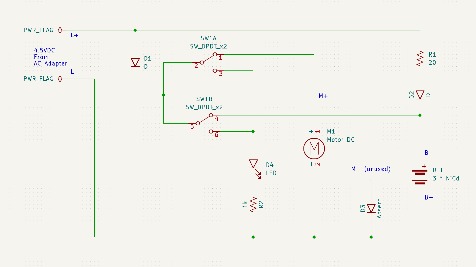
The execution, though, turned out to be very different. What caught my attention about this board during the teardown earlier was the absence of diode D3, and the motor’s negative terminal was connected directly to the battery negative terminal via a wire instead of the designated “M-” connection point on this circuit board. Probing component connections, I came up with this schematic:
The absent diode D3 is directly connected to the unused M- terminal. My best guess was an intent to prevent the motor from sending reversing voltage into the battery pack, but that doesn’t seem like a very likely scenario in a hair clipper. Maybe they thought it was when they designed the circuit board, and then decided it was not a problem?
20 Ohm resistor R1 is in line with diode D2, leading to battery positive. This pair would only come into play when the device is charging. So D2 would be in charge of making sure the battery doesn’t feed back into charging port terminals L+/L-, and R1 performs some sort of voltage or current regulation for charging. The Remington clipper circuit board had a provision for such a resistor, but absent from my unit. Presumably they decided it was not necessary.
While D2 is in charge of making sure the batter doesn’t feed back into charging terminals while the switch is set to charge, D1 exists to do the same job when the switch is set to run motor. I found it interesting they decided against consolidating those two diodes into a single diode as Remington did. The difference between those two paths is R1, so the absence of its counterpart in Remington would be related in some way.
Charging indicator LED is in series with a current-limiting resistor R2. 1k Ohm would keep that LED pretty dim, but it doesn’t need to be particularly bright. The Remington clipper circuit board had a resistor in parallel with the LED whose purpose mystified me. There is no counterpart resistor here so it must not be intrinsic to hair clippers.
The most surprising detail was the path from battery positive to motor positive. Obviously that would be routed through the switch, but I didn’t expect to find that it was routed back through the switch a second time. This series path would double the electrical resistance added by the switch. In contrast, the Remington board runs motor power through the switch in parallel, halving the switch resistance. Why did Conair do it this way? The Remington approach made more sense given my level of knowledge.
Due to the relatively simple appearance of these two hair clipper control boards, I thought it would be easy to fully understand what they do once I captured their schematic. But as it turned out, they each have their own mysteries. I hope to eventually understand such things as I continue learning electronics design by reverse-engineering more circuit boards.
After completing an upgrade for my workbench lighting solution, I went back to my most recently learned skill: drawing electronic schematics in KiCad. I’ve learned that skill once and lost it. I don’t want it to atrophy again after this second round. I want to practice with a few simple things and the top of my electronics waste pile is the circuit board from my Remington hair clipper (HC-920) teardown. Great, I’ll start with that!
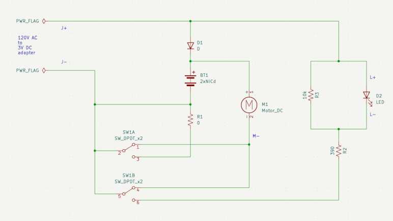
When I looked over this board briefly, the absence of resistor R1 drew my attention. Instead of an actual resistor, this part of the circuit has a solder bridge on the back turning R1 into a zero Ohm resistor. How did this circuit work, and what role would a non-zero R1 have played?
After tracing through how the components are interconnected and drawing them out in a schematic, I’m no closer to an answer. (The dual-pole dual-throw switch is drawn in the “motor running” position.)
The easiest part to understand concern the red LED that indicates charging is underway. When the switch is in the non-running position, the LED receives power from the charging power adapter. R2 is a 390 Ohm current limiting resistor for the LED, which I expected. R3 is a 10K Ohm resistor parallel with the LED, which was a surprise. Why is R3 here? Drawing a bit of power away from the LED would have made it a bit dimmer, but if that’s the objective, it seems easier to increase resistance of R2 instead of adding another component to the board. I assume this design has been optimized to squeeze every penny out of production cost, so if R3 survived that process it must have some importance I don’t understand.
Terminals J+/J- provide 3V DC from the charging adapter. In parallel with the red LED, it passes through diode D1 to the battery. The diode makes sense to ensure battery power doesn’t feed back out to to the charging port or wasted on the red LED.
When the switch is in the running position, as shown in the schematic, the motor positive and negative terminals have continuity with battery positive and negative. It also has continuity with terminals J+/J-. Interesting, as this implies I could run the motor directly off the charging adapter if it was plugged in, turning this cordless hair clipper into a wired hair clipper. This would have been an option to run the clipper if the batteries had died. I don’t think I was aware of this capability and it didn’t even occur to me to try!
That leaves the mystery resistor R1, which runs between the batter negative terminal and J- terminal when the switch is in the non-running position. This implies R1 is involved in limiting charging voltage or current on the battery charging circuit. However, there was a black wire directly connecting battery negative to J-, which would have bypassed this resistor on the circuit board. And if we cut that wire the motor would have no way to receive battery power. Maybe I’ve made a mistake in my schematic, though I couldn’t find it if so. But if not, R1 makes no sense in this wiring arrangement. It must have been designed to support a different physical wiring arrangement. So given what we have here, it makes sense R1 is missing and bridged with a blob of solder.
One of the reasons I started looking at Angular web development framework a few years ago was because it was backed by Google and I saw that as a positive thing at the time. One of the reasons I looked at Marko web development framework now is because I no longer see Google backing as a positive thing.
I remember Google when it was a young and idealistic startup and today’s mega corporation has strayed quite far from its “Don’t be evil” origins. A few years ago I would enthusiastically add new Google products to my life. Today I am skeptical of new Google launches, due to fiascos like Stadia and disruptions caused by their historical tendencies to kill products. And of the Google products I’m already using, I keep my eyes open for alternatives that might help me reduce Google’s grip on my digital life.
As part of this transition, I’m working to reduce reliance on Google’s Chrome browser. I have Firefox installed but remembering to use it instead of Chrome requires breaking longtime habits. My latest motivation to do so is Google’s aggressive push for additional user tracking to increase its advertising revenue, and maybe this time my switchover will stick. I plan to keep Chrome around to run Google-specific properties like Gmail and YouTube (since Google is tracking me there anyway) but use Firefox for everything else.
So far there’s nothing in Firefox that made me regret switching, and I’ve found a feature that might make the switch worthwhile all on its own: I can make Firefox PDF viewer default to “Page Fit”!
I remember when downloading Adobe’s free Acrobat reader was a standard part of setting up a new machine. Today, PDF’s ubiquity meant browsers tend to include PDF viewing capability. I’m tired of Adobe trying sneaky things to generate revenue from free Acrobat reader, so I am happy to skip that download. But there was one little annoyance: I prefer to read my PDF with each page zoomed to fit the window. I know how to set that default on Acrobat reader but that’s not how it opens by default in a browser’s integrated PDF viewer window.
I never found a way to do what I want in Chrome’s PDF viewer. Microsoft’s Chromium-based Edge browser is a little better: there’s a keyboard shortcut Control + “\” to change zoom setting. I got in the habit of pressing Control+”\” twice whenever I opened a PDF in Edge, which zooms to page, but it would be nice if I didn’t even have to do that. A web search found confirmation this was not possible in Edge.
By default, Firefox opens PDF in “Automatic Zoom” mode, which isn’t what I want. I searched for a Firefox equivalent to Control+”\” in Edge but I found something better: this support page with instructions on how to change that default, it even had a link to the GitHub pull request that implemented the feature. Sweet!
In case those links go dead in the future, here’s the summary:
Type “about:config” into Firefox address bar
We will see a warning screen and we have to decide to accept the risk and continue.
In the search box, type “pdfjs.defaultZoomValue“
Click the pencil to edit.
Type in page-fit. (Or, if that’s not personal preference, one of the following supported options: auto, page-actual, page-fit or page-width.)
Click the check icon to save.
Now Firefox PDF viewer will open with my preferred zoom setting, no need to press Control+”\” twice.
If Google had left Chrome alone as a consumer-friendly browser, I don’t know if Firefox PDF default zoom capability would have enticed me to switch. However, now that Google is getting greedy and I’m starting to use Firefox, this feature is definitely one that will make me want to stay with Firefox. In the meantime, another Google “revenue enhancement” policy change motivated me to start using a real camera again.
I previously observed the actuator coil ends are alternately energized to battery voltage with the other end at ground for about 1.25ms. Then both ends sat at ground level for around 0.75ms before repeating with the coil energized in the opposite direction.
This time I connected the four channels of my oscilloscope to four test pads each associated with a MOSFET control gate. I started a brush cycle and got this:
There were two mysteries with this plot:
Why are there only two colors visible when four channels are active?
Why is the alternating pattern occurring for 0.75ms (duration of the rest period) at a time, instead of the 1.25ms (duration of the actively energized time)?
I figured out the first one by pushing each of the four channel select buttons in turn, which brings their color to the foreground. It turns out that two of the MOSFETs corresponding to the same end of the coil always receive the same control voltages, so they overlap on the plot and only one of those two colors is visible. The yellow line corresponds to TP3, P-channel MOSFET for coil output 2. It is always in sync and thus plots over the cyan line, which is TP9 and N-channel MOSFET for coil output 2. If I push the channel 3 button (cyan) it would completely obscure the yellow line. Likewise, the green line here is TP10 (N1) masking the magenta line for TP4 (P1). If I press channel 2 (magenta) select, it draws exactly where the green is and mask all green.
It makes some sense for both MOSFETs corresponding to one end of the coil to stay in sync. We want only one of those to be conducting from source to drain at any given time. If they are both active, that would cause a short circuit between the battery power and ground rails. Since one is a P-channel MOSFET and the other a N-channel, both receiving the same signal means one turns on and the other turns off.
But if they are in sync, why bother using two separate control pins from the microcontroller? Why not just have a single signal that goes to both MOSFETs? I learned this was a difference between the ideal world and the real world. In the real world, MOSFETs take a tiny bit of time to ramp up and down. If we use a common signal wire, one MOSFET will start to turn on while the other one is still ramping off within this narrow time window and cause a short circuit. Having two separate control signals allow the microcontroller to turn one off, wait a bit for it to ramp down, before turning the other one on.
If that’s the case, though, it’s not visible in my oscilloscope plot at 1ms/grid resolution. I selected channel 2 (magenta TP4 P1) and 4 (green TP10 N1) and started increasing the time resolution until I saw a clear difference in timing, around 3us apart, between those two signals. I love it when I can see real-world necessities confirmed in an actual implementation like this.
The next challenge is figuring out why MOSFETs look like they’re energizing the coil for 0.75ms out of the cycle, instead of 1.25ms like I expected. It didn’t make sense, so I started questioning my “known facts” until I got to cycle time. I have an oscilloscope plot on hand showing 1.25ms ON time and 0.75ms OFF time, but that wasn’t captured at the same time as the MOSFET signal plots. To verify this “known fact” I moved one of the oscilloscope probes over to coil terminal 1.
The coil is ON for 0.75ms! The “known fact” of 1.25ms ON time was wrong. I had assumed the cycle time would have stayed consistent, but something changed between the previous oscilloscope session and this session to change those cycle times. If it didn’t happen to land inversed from before (say 1.5ms and 0.5ms) I would have realized my assumption was wrong, but it just happened to end up inversed and confused me until I identified my incorrect assumption.
Valuable lesson learned: given the luxury of a multichannel oscilloscope, use those channels to capture related data at the same time. Comparing plots across different instrumentation sessions risks outdated information leading to bad conclusions.
With that, I believe my investigation of Philips Sonicare HX6530 circuit board is complete. I want to apply these lessons and build my own brush actuator control circuit, but that will be a future project. Some unrelated things worth noting happened while I had my nose in this circuit board, starting with how Unity corporation’s management alienated users.
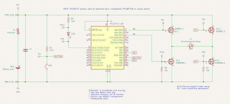
I probed the circuit board salvaged from a retired Philips Sonicare HX6530 electric toothbrush, trying to understand how it controls the brushing actuator. I compiled my findings into a partially reconstructed schematic of this circuit board, and it looks like a H-bridge or at least a similar arrangement of components.
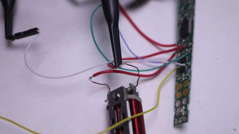
I made effort to figure out which test points corresponded to which locations on this schematic, because that’s my next step: solder wires so I could connect them to my oscilloscope and watch them run. These test points were intended to mesh with a specially designed test harness with pogo pins corresponding to those locations, but I decided that was too much effort for the sake of curiosity and went with direct soldering.
Color coding will help me keep from getting my wires mixed up. Yellow, blue, and green wires were soldered to test points so I could connect them to oscilloscope channels that use similar colors. This idea occurred to me just after I soldered a white wire to TP4. I briefly contemplated unsoldering the white wire and replacing it with a red one for the sake of consistency, but decided three out of four was good enough to avoid ambiguity.
I powered up the control board with my bench power supply set to 4V, here’s what things looked like in an idle state. TP3 and TP4 corresponding to the two P-channel MOSFET gates float at Vcc. TP9 and TP10 correspond to the two N-channel MOSFET gates with pull-down resistors are at ground. This was as expected.
Here’s an oscilloscope plot I captured earlier, measuring two ends of the coil relative to the ground plane of the control board. We see the coil is driven in one direction for roughly 1.25ms, then not powered for about 0.75ms. Then it is driven in the other direction for roughly 1.25ms, followed by another 0.75ms of rest time. Given this plot, I would expect to see MOSFET gate voltages go to a pattern consistent with driving the coil one way for 1.25ms, followed by 0.75ms of idle state, then flip the other way for 1.25ms, and then another 0.75ms of idle, and repeat.
My expectation did not match what I saw on the oscilloscope screen. All four MOSFET gates were raised high for ~1.25ms, followed by 0.75ms of activity in an alternating pattern. I expected an alternating pattern, but that was supposed to run for 1.25ms, not 0.75ms. Furthermore, there were fewer colors visible on screen than I had expected. What happened to cyan and magenta (channel 2 and 3)? I have to dig deeper to understand what I’m seeing.
Armed with the knowledge granted by “Getting Started in KiCad” guide, I can now take bits and pieces of information gleaned from a circuit board and compile them into a partial reverse-engineered schematic. The first (of hopefully many) subject of these exercises is the Philips Sonicare HX6530 circuit board. I looked it over earlier taking note of components I recognized but didn’t dig deeper into how they are connected. For this second pass, I am armed with an electrical continuity meter to probe how they connect.
To trace routes across this circuit board, I started with magnifying glasses but then moved to a digital camera with a macro lens. This allowed me to put pictures of the front and back together in a slide show and rapidly go back and forth between them to trace routes across layer vias. It worked really well this time, and I expect to continue evolving that system in future explorations.
The goal of these exercises is to control the salvaged brush actuator myself, so I focused on the actuator control MOSFETs to the left of the PIC16F726 microcontroller. I worked out most of the circuitry to the left of the PIC16F726 all the way up to the LED at the far left edge. I mostly ignored the other half of the circuit board, as it dealt with charging and unpopulated pads imply absent features. The only thing I worked out on that side is C1 as a decoupling capacitor between Vdd and Gnd.
The user interface button and feedback LED turned out to be straightforward implementations, easily probed so I put them in my schematic. The focus is on the array of four MOSFETs on the right, surrounding the actuator coil.
At a high level, I recognize the arrangement as an H-bridge circuit popular in motor control. I guess this actuator coil is a motor in a sense. But if so, why did Philips engineers decide to implement their own with two components (each a package of dual MOSFETs) instead of using a single-chip H-bridge solution like a DRV8833? It might be cost, or it might be an important difference between this brush actuator and a generic DC motor.
I notice an asymmetry in this circuit. Dual N-channel MOSFETs each got a 33k pull-down resistor (R4 and R5) on their control gates, but the dual P-channel MOSFETs went without any kind of pull-up or pull-down resistor. Why is it OK to leave them floating? I don’t know.
I didn’t find any flyback diodes on this circuit. My rudimentary understanding of driving inductive loads (such as an actuator coil) is that we need flyback diodes to protect the circuit against voltage spikes when the electromagnetic field in the coil collapses. A generic L298N motor driver module has clearly visible diodes for this purpose. Newer motor control modules like DRV8833 has such capability built-in. DRV8833 datasheet section 7.3.2 Bridge Control and Decay Modes cover this topic.. MOSFETs have a “body diode” intrinsic to their design, perhaps they were sufficient for flyback protection?
It was very instructive to poke around this circuit board and assemble the bits and pieces I teased out into a KiCad schematic. It is incomplete and likely inaccurate, and it raised more questions than it answered. All signs that I still have a lot to learn. And I will start by putting the circuit board under my oscilloscope to compare its measured behavior against what I expect from the schematic.
I retired my Philips MG7790 hair trimmer because it would stop in the middle of a haircut. Its red LED flashing an error, which usually means the battery has run out of juice. But it would do this within a few minutes after fully charged, very disappointing when it was advertised with up to six hours of runtime on a full battery. I decided the battery has degraded and maybe replacing its battery would get it back up and running. I disassembled its internals to get to the battery, a single lithium-ion cell in the commodity 18650 cylindrical form factor.
Measuring the battery’s voltage, I expected to see a low value somewhere below 3.5V. But it actually read 4.1V which is effectively full for a healthy single lithium-ion cell. Maybe its voltage would drop under a bit of load? I started the motor running, and the voltage barely budged. It stayed close to 4.1V as the motor spun freely for twenty minutes, longer than it’s done recently.
If the battery is fine, I have misdiagnosed the issue. I started thinking about possibilities:
I originally thought it was premature death of a dodgy battery. But the cell was made by LG and generally speaking they know what they are doing in the field of battery manufacture. Especially a well-known commodity form factor like 18650 cylindrical cells.
A battery would suffer accelerated wear if it was undersized for the task. But with up to six hours of runtime on a full charge, this battery is massively overprovisioned and shouldn’t have been stressed.
Perhaps the stress came from premature death of a motor component. As a quick test, I spun the motor shaft by hand while the thing was turned off. It turned smoothly and without any squeaking noises, so it’s probably not due to premature bearing death. Besides, it was a genuine Mabuchi, they know motors.
Perhaps this was a result of poor overall system design? But this isn’t a cheap no-name budget priced item. Philips/Norelco has been in this business for a long time, and they should know what they are doing.
What have I missed? This is a mechanically simple device and there aren’t too many other things for me to look at. I started thinking about my twenty-minute runtime test, which had the motor spinning without driving anything.
The red LED pulsed during this test. Since the voltage was high and the motor was still running, that red LED must be complaining about some problem other than low battery.
During the teardown I unsoldered the battery from the circuit board, the first time they’ve been separated since factory assembly and the first time this circuit board has been completely without power. Maybe the pulsing red LED is complaining about some sort of cold startup condition? I plugged in the AC adapter to let it charge up to full. After that, the red LED stayed dark if I started the motor. I guess it needed to do some sort of battery calibration/reference on external power.
But now there’s no error, what should I look at next? During these tests, the motor spun freely because everything was still disassembled, and it was not possible to attach a cutting element. Process of elimination says I should take a closer look at that cutting element.
For comparison, both Conair and Remington hair clippers had two prominent fasteners holding the static blade in place.
Once the static blade was removed, we could clean all around the reciprocating blade. As seen here on the Conair unit.
When we could remove to access the motor driven crank volume and clean hair out of there, too. As seen here on the Remington unit.
Back to this Philips, whose cutting element incorporated both static and reciprocating blades. It’s easy to pop them off as a single unit to access this hair chamber as per cleaning instructions. The manual doesn’t say anything about taking the cutting element apart, but I’m going to do it because I am running out of places to look.
The static blade is held by a pair of tiny little Torx screws, more annoying than those easy large fasteners of Conair and Remington hair clippers. Once the static blade was freed I could see the volume between static and reciprocating blades is fully packed with fragments pressed together into a nearly solid brick of hair. The cleaning instruction never mentioned cleaning this area. The tiny little self-tapping plastic screws won’t last many fasten/unfasten cycles implying this wasn’t intended to be a user-serviceable cleaning area.
Being packed with hair fragments meant the reciprocating blade would have required more motor effort to move, which in turn would have increased strain on the circuit and battery. Maybe this was why the battery drained quickly, or perhaps the red LED didn’t signify low battery at all. Perhaps the motor stalled, or perhaps the motor control circuit overheated. I have no idea what that red LED was trying to tell me, but I certainly didn’t get “you need to disassemble and clean the cutting element” from a dull red LED.
Once all of the packed-in hair was removed and the cutting element reassembled, the reciprocating blade was much easier to move by hand. I tested this repair by reassembling everything and trimmed my hair with it. This time, the motor didn’t stop partway through the process. Yay, success! Since I already had a newer unit in service, I will keep this older unit around as backup. It’s no longer waterproof, but it runs again. As a bonus, this episode also taught me valuable lessons on how to clean the newer unit to keep it healthy.
My solar power monitor uses components I salvaged from a broken USB power bank. After a year and a half of daily charge cycling, the charging circuit has gone out. I replaced it with an inexpensive commodity battery management system (BMS) module based on a 4056 chip. Then I let the module run unmodified for two days to verify everything worked as advertised.
These modules shipped with charging rate configured at one amp. The general rule of thumb is charging rate should stay below 1C, which is 2.6A for these 2.6Ah capacity cells, so the default should be fine. But I wanted to lower the charging rate for several reasons:
This battery cell is almost a decade old now, and it is natural for older cells to have reduced capacity along with reduced tolerance for charging speed.
Charging at slower gentler rates improves battery longevity, hopefully making this old battery last even longer.
There’s no rush: drawing from the solar panel, this thing can charge over entire span of daylight hours when panels are producing power.
By reducing the power demand, I can activate this charging circuit even when the solar panels produce little power such as during overcast or rainy days.
By slowly charging during daylight hours, it reduces stress on the battery because it would only have to run the microcontroller during early morning and early evening when sunlight is scant.
Due to those reasons, I had ambition to slow the charging rate using original USB power bank charging circuit as well, but I didn’t know how to work with the unmarked chip. Switching to a commodity BMS chip meant I can get more information. I’m not sure exactly whose 4056 chip I have here. But as they seemed to be interchangeable commodities, I just downloaded one of them and learned charging rate is controlled by a resistor between pin 2 (PROG) and ground. The formula is (Charging current) = 1200/(RPROG). Probing this module, I find the charge rate control resistor to be the one labeled R3 and its tiny number says “122”. I understand that to mean 12 * 102 = 1200Ω = 1.2 kΩ. This matches expectation with the formula 1A = 1200/1200.
The beauty of math is infinite, but real-world circuits have limits. What is a practical minimum for charging rate? The datasheet I consulted gave several examples, the lowest is 0.12A rate via a 10kΩ resistor. Conveniently, the just-retired USB power bank circuit board has a 10kΩ resistor (labeled “103” meaning 10 * 103 = 10000Ω) on board. Since it’s not doing anything anymore, I can pull it off and swap it for the default resistor at position R3. My lackluster soldering skill with surface mount devices (SMD) wasn’t pretty, but it’s functional.
Now I have a low-demand charging circuit for my solar power monitor, letting me run it across more weather conditions while gently charging the single old lithium-ion battery cell to extend its operating life. It would be nice if I can do more to extend battery longevity: lithium-ion chemistry batteries are stressed when they are fully charged or fully discharged, so they are best kept partially charged. In this particular project, I handle both in software running on my ESP8266. It goes to deep sleep before voltage drops to a critical level. It also disables the solar panel DC buck converter before the battery is fully charged. It’d be nice if I could reduce software complexity by doing everything onboard the BMS module, but I can’t. Low cutoff voltage is controlled by the mystery chip at location U2, and max charging voltage is fixed at 4.2V for a 4056 chip.
Perhaps in the future I’ll find a charging module that would let me modify those parameters, but for today this is good enough for my solar monitoring project to return to service so I can resume my LEGO nostalgia tour. I was just getting to the good part: LEGO Technic sets!
My solar panel power monitor project incorporated an old USB power bank for its battery and charger circuit, bypassing its broken USB power output circuit. After a year and a half of daily cycling, the charging circuit has broken down as well. I’m happy I got that extra life out of a USB power bank circuit board that would otherwise have been disposed of. The battery is still going, but I will need a replacement circuit to manage charging it.
With the widespread adoption of lithium-ion battery power, I have many solutions to choose from. The lowest bidder du jour on Amazon was this vendor selling a multipack of 40 BMS modules (*). It arrived in a single 10×4 sheet for the me to break apart as needed, similar to a batch of buck converters I bought earlier. I like this approach much better than loosely packed pieces that may damage each other in shipping.
The main chip in the center of this module had “4056H” printed on top. Many vendors on Amazon/AliExpress/etc. also single-cell BMS modules with this general design, not necessarily with “4056H” on top but all with some variation of “4056” with different prefix/suffix letters. A search for “4056” returned many chips from different companies that seemed to be interchangeable. I assume someone had a successful product that was then copied by many others, but I don’t know who the original was. The same goes for this particular breakout board module design. Looks like both the module and the chip at the center of it have become commodities.
This module also advertised protection against battery over discharge with a 3A current limit and 2.5V voltage limit, but that’s beyond the scope of a 4056 chip. This module must have additional components handling such protection. I see one chip labeled 8205A, which appears to be a dual N-channel MOSFET chip suited for output cutoff controlled by the chip at position U2. I don’t know how to dig deeper because U2 is unmarked on my purchase, but I have learned enough to put this module to work.
The module with its six soldering points is fairly straightforward to incorporate into my project:
There are pads on either side of the USB micro-B socket for 5V power input, one of them marked “+”. They are soldered to the existing buck converter dropping solar panel DC power down to 5V.
Pins labeled “B+” and “B-” connect to the positive and negative terminals of the 18650 battery cell.
Remaining pins labeled “OUT+” and “OUT-” are connected to the ESP8266 microcontroller module.
Fast forward to this week: browsing my recent data in Home Assistant, I noticed the solar monitor battery voltage has been erratic for a few days. It usually charges up in the early morning soon after sunrise, then gradually fall through the day until the next morning. But now it no longer charges on a smooth curve in the morning, what’s going on? Looking at charging status LEDs, I can see it changing state erratically once every few seconds. Maybe blinking in charging sequence for a bit, then maybe all four would be illuminated as if the battery was fully charged, then they would go out as if charging power disappeared, or some combination of those states.
Pulling out my voltmeter, I checked the following candidate explanations:
Perhaps the buck converter I had used to convert solar panel DC voltage down to 5V is misbehaving? I checked the voltage of enable pin: it is steady at 3.3V. I checked the output voltage: a steady 4.9V with no fluctuation. The buck converter seems to be performing nominally.
Perhaps the lithium-ion battery cell is failing? I monitored the battery terminal voltage as the charger cycled through its charging/not-charging states, looking to see if the battery voltage is behaving unexpectedly. Maybe it dropped below critical minimum (3V) or shot up to maximum (4.2V) upon charge. Neither was the case: voltage fluctuated around 3.6V. A little higher when charging and a little lower when discharging, signs of a nominally working battery cell.
If the power input is good and the battery looks good, process of elimination says the problem is the repurposed power bank charging circuit between them. This was not a huge surprise since this piece of electronics was already known to be defective: The reason I took it apart was because the output stage could no longer deliver 5V USB power output. I’m actually rather pleased I got another year and a half of useful life out of the power input charging stage before the whole thing gave out.
Comparing year-and-a-half old picture (left) against current state (right), the most obvious sign of degradation is near the micro-USB power input port, the yellow epoxy towards one corner touching component U9 has visibly darkened. Is it charring from overheating, or some other degradation? That is not clear. What is clear is that I now need something else to manage charging the single 18650 lithium-ion battery cell.
I liked the potential promise of doing CAD via code instead of drawings, but current implementations left me unconvinced. Partly because today’s existing code-cad solutions are built on OpenSCAD (I’m not a fan) and partly because it is a huge change in mindset. I might find motivation to give it an honest effort in the future, but for the immediate future I’ll retreat back to FreeCAD and the sketch-based workflow I’ve been familiar with. Part of this decision came from getting a sense of FreeCAD’s direction in their “What’s going on at FreeCAD?” communications.
The biggest question I had is about the infamous topological naming problem. (TNP) This always comes up whenever people discuss switching from a commercial closed-source CAD package to open-source FreeCAD. Opinions range on a wide spectrum from the snobby “only dumb users run into TNP” to “widespread adoption would not be possible until TNP is mitigated” to dismissive “TNP exists because FreeCAD is not a serious project”.
I don’t personally have an opinion on FreeCAD TNP, since I haven’t used it very much yet. But I know enough to be aware it’s not exclusive to FreeCAD. Many other CAD packages have problems along those veins to varying degrees. For my Sawppy CAD file in Onshape, part geometry changes are sometimes followed by notifications of failed fillet operations. Or worse, fillet operations that don’t fail but went someplace unexpected.
But my opinion is not as important as the opinion of the people behind the project. Do they even consider TNP to be a problem that needs solving? Thanks to “What’s going on at FreeCAD?” I learned the answer is a definite YES. In fact, they consider it one of the (if not THE) top problems that need to be solved before they can declare FreeCAD version 1.0.
I don’t understand enough FreeCAD internals to understand how they intend to address TNP, but there IS a plan, and the project is at a critical stage. The underlying support infrastructure is in place, but starting to utilize that infrastructure across FreeCAD will likely degrade performance until everything is done. This will be the next public release. It won’t disrupt users who aren’t part of making the great TNP fix, while providing a stable foundation for people who are. Allowing them to implement and test TNP solutions. (And if things go seriously wrong, it leaves the option open to rip out that infrastructure and try a different approach without breaking future versions.) Since TNP is not fixed yet, the next release will not be 1.0. It’ll just be the next increment: 0.21.
I first started looking at FreeCAD shortly after 0.19 released and online resources (aimed at 0.18 and earlier) were in turmoil working to update. Today, 0.20 had been out for over a year and most resources have stabilized. I should take advantage of that and learn 0.20 as quickly as I can before 0.21 causes another round of disruptions.
So where should I start? There was a recent Hackaday post about FreeCAD, which elicited the usual cacophony of comments arguing about TNP. But in between the noise I noticed multiple recommendations for MangoJelly’s YouTube tutorial series. Video tutorial is not my preferred format, but if it’s a popular place to start, I’m willing to give it a shot.
CadHub is an advocate of defining 3D models using lines code instead of the more traditional interactive UI descended from pre-computer drafting boards. It holds a lot of promise and it linked to several projects making those ideas real. The problem is they’re built around OpenSCAD which, while not as bad as I thought, is still hobbled by some fairly fundamental limitations. I wouldn’t say I’m a convert to the cause just yet.
I am happy to see these code-cad projects implementing some of my wishlist for collaborative CAD capabilities. However, taking a step back, I noticed there is no fundamental requirement linking the two. Take the example of branching and merging: this is a valuable feature that has been implemented in Autodesk Fusion 360 and in OnShape, neither of which are code-cad systems. Similarly, there’s nothing fundamentally impossible about adding automated drawing regeneration, integration with documentation systems, etc. to non-code-cad systems.
I will admit it is easier for code-cad systems to implement such features in the context of git. Since code-cad is based on code and git is specifically designed to work with code. There’s a barrier to climb for non-code data files, but git can be used to version control non-text files like images. Doing so restricts conflict resolution to granularity of entire files: we have to choose one file, or the other, and couldn’t merge between them like we could with text files. Or at least, that’s the situation by default. I’m not familiar enough with the git protocol to know if it’s possible to patch in a binary file format merging mechanism. I do know it’s possible to introduce a binary file change difference visualizer, because GitHub offers support for select non-code file formats.
But there’s more to a collaborative information management system than git, as shown by Fusion 360 and Onshape. While code-cad is A way forward to reach items on my wishlist, it may not be THE way forward. This little research tour has been extremely educational, but I should get back to studying FreeCAD.
CadHub is an advocate for the general idea of 3D CAD models built from lines of code instead an electronic representation of a drafting board. This approach (“code-cad”) holds many promises of meeting my wishlist for an open-source collaborative CAD solution. While theoretically applicable for all code-based CAD solutions, the current reality is almost exclusively built around OpenSCAD.
I briefly dipped my toes into OpenSCAD for a bit, but I was really turned off when I learned the prescribed method to perform a fillet operation in OpenSCAD is to use operators like Minkowski sums and convex hulls. They are conceptually straightforward but in practice it takes a long time to chew through the math. Making matters worse, OpenSCAD’s CSG kernel is limited to a single thread underutilizing modern multicore processors. In contrast, the OpenCascade 3D kernel can easily handle fillets and has partial support for multicore computation. (Whether that capability is enabled in FreeCAD, CadQuery, etc. is a separate issue that depends on their respective OCCT integration.)
Despite my distain I have to admit such theoretical superiority has to be balanced against OpenSCAD’s real-world advantages that are already up and running. CadHub blog talked about integrating code-cad into software CI/CD pipelines. That page linked to two projects which have already put the concept into practice: OpenFlexture Microscope and a DIY Split-Flap display. Both of these projects define their 3D designs via OpenSCAD, enabling automation to keep their project documentation in sync. This is pretty awesome. And some OpenSCAD users shared the same objections I do, except some of them actually helped solve the problem. CadHub itself has something called the “Round Anything” library that makes some OpenSCAD fillets (especially internal fillets) less painful.