AS7341 Spectral Color Sensor with Mozzi on AVR Arduino

Looks like I will never learn how to build custom configurations for AS7341 SMUX, but at least I have presets I could copy/paste and that’s good enough for my hobbyist level project. The goal is to convert I2C communication from Arduino’s standard Wire library to the twi_nonblock library bundled as part of Mozzi library. Arduino Wire library would block execution while I2C communication is ongoing, which causes audible glitches with Mozzi sketches. Converting to twi_nonblock avoids that issue.

Using Adafruit’s AS7341 Arduino library and sample sketches as my guide, it was relatively straightforward to converting initialization routines. Partly because most of them were single-register writes, but mostly because non-blocking isn’t a big concern for setup. I could get away with some blocking operations which also verified I2C hardware was working before adding the variable of nonblocking behavior into the mix.

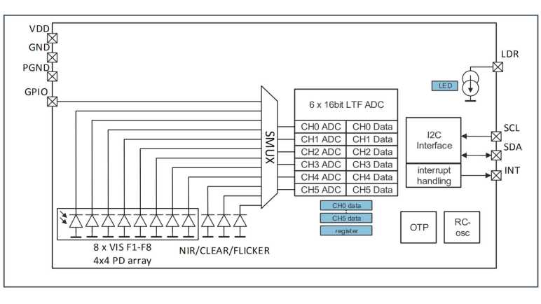
To replicate Adafruit’s readAllChannels() behavior in a nonblocking manner, I split the task into three levels of state machines to track asynchronous actions:

  • Lowest level state machine tracks a single I2C read operation. Write the address, start a read, and copy the results.
  • Mid level state machine pulls data from all 6 AS7341 ADC. This means setting up SMUX to one of two presets then waiting for that to complete. Start sensor integration, then wait for that to complete. And finally copy sensor results. Each read operation is delegated to the lower level state machine.
  • High level state machine runs the mid-level state machine twice, once for each SMUX preset configuration.

Once that high level state machine runs through both SMUX preset configurations, we have data from 10 spectral sensors. The flicker detector is the 11th sensor and not used here. This replicates the results of Adafruit’s readAllChannels() without its blocking behavior. Getting there required an implementation which is significantly different. (I don’t think I copied any Adafruit code.)

While putting this project together, my test just printed all ten sensor values out to serial console. In order to make things a little more interesting, I brought this back full circle and emulated the behavior of Emily Velasco’s color organ experiment. Or at least, an earlier version of it that played a single note depending on which sensor had returned highest count. (Emily has since experimented with vibrato and chords.) I added a lot of comments my version of the experiment hopefully making it suitable as a learning example. As a “Thank You” to Emily for introducing me to the AS7341, I packaged this project into a pull request on her color organ repository, which she accepted and merged.

This is not the end of the story. twi_nonblock supports only AVR-based Arduino boards like the ATmega328P-based Arduino Nano I used for this project. What about processors at the heart of other Arduino-compatible boards like the ESP32? They can’t use twi_nonblock and would have to do something else for glitch-free Mozzi audio. That’ll be a separate challenge to tackle.


Code for this project is publicly available on GitHub.

Sample Code Gave Incomplete Picture of AS7341 SMUX Configuration

Reading through Adafruit AS7341 Arduino library implementation of readAllChannels(), I was happy to see it mostly confirmed information I understood from datasheet reading. It also had something else: how to configure AS7341 sensor multiplexor (SMUX). Details of which were critical information completely missing from the datasheet, mere a note that AMS provides sample code. [Update: Details were in an Application Note.] I say sample code is a poor substitute for proper documentation and my position remains unchanged.

I thought I might have a good shot at figuring out SMUX configuration registers, given that I have found three sample points. DFRobot has an Arduino AS7341 library. Adafruit has their own implementation of an Arduino AS7341 library. And hidden in the examples folder of Adafruit’s library is an Arduino sketch that doesn’t use Adafruit’s library at all, written by an AMS application support engineer. Comparing and contrasting between them should tell me a lot!

Unfortunately, as soon as I took a closer look my expectation went down in flames. These three examples are writing the exact same bytes to the exact same registers. There’s nothing to compare and contrast at all. This feels like someone at AMS wrote a SMUX configuration at one point and it’s just been copied and pasted ever since. All we really have to work with are the skimpy comments in these configuration routines.

Based on these comments, each register corresponds to a single sensor, except when it controls two sensors. Bits in the register control which ADC is connected. It was easy to infer that zero representing no connection to any ADC at all, but other than that the bits are inconsistent. Setting register 0x0F to 0x30 supposedly connected to ADC2, but for register 0x0A it was 0x03 that connected to ADC2. Some of the sensors have a “left” and “right” but it’s not clear what that means. My best guess is from the datasheet figure showing sensor array layout:

Maybe “F3 left set to ADC2” means connecting only the left side F3 sensor, leaving the right side F3 sensor unused? That would mean we’re using half the available sensor area to gather light, which seems sub-optimal.

And most critically, the comments weren’t enough for me to figure out how I’d create a different SMUX configuration. There’s nothing about any of these in the datasheet, which remains my biggest complaint to AMS. The only description I found in the datasheet is that flicker detection sensor must be connected to ADC5.

One odd thing I noticed about this copied-and-pasted code snippet is the fact it sends twenty bytes of SMUX configuration as twenty write operations of single bytes to sequential registers 0x00 through 0x13 inclusive. Why do it in such an efficient way? For my project I converted that to a faster and more efficient single write operation of twenty bytes and it seems to work.

The good news is that these sample code snippets help us configure SMUX to do something useful in line with functionality demonstrated by these samples. The bad news is that we don’t have enough information to design and build our own SMUX configurations to suit specific needs. I guess if someone wants to use AS7341 professionally they can ask AMS application support team to build a custom SMUX configuration for them. For an electronics hobbyist like myself, these fixed configurations are sufficient for me to complete my project, but I am still grumpy with AMS about it.


Code for this project is publicly available on GitHub.

Unrolling Adafruit AS7341 readAllChannels()

After successfully reading an AS7341’s product ID via a non-blocking I2C API, I have gained confidence I can replicate any existing AS7341 library’s actions with the non-blocking I2C API. This way it will play nice with Mozzi library. I decided to focus on Adafruit_AS7341::readAllChanels() because it seemed like the most useful one to convert to non-blocking operation. It was used in multiple examples as well as Emily’s color organ project.

bool Adafruit_AS7341::readAllChannels(uint16_t *readings_buffer) {

  setSMUXLowChannels(true);        // Configure SMUX to read low channels
  enableSpectralMeasurement(true); // Start integration
  delayForData(0);                 // I'll wait for you for all time

  Adafruit_BusIO_Register channel_data_reg =
      Adafruit_BusIO_Register(i2c_dev, AS7341_CH0_DATA_L, 2);

  bool low_success = channel_data_reg.read((uint8_t *)readings_buffer, 12);

  setSMUXLowChannels(false);       // Configure SMUX to read high channels
  enableSpectralMeasurement(true); // Start integration
  delayForData(0);                 // I'll wait for you for all time

  return low_success &&
         channel_data_reg.read((uint8_t *)&readings_buffer[6], 12);
}

Examining this code, we can see it does the same thing twice, differing only in a single boolean parameter to setSMUXLowChannels. This reflects AS7341 architecture where we have more sensors than ADCs so we have to configure SMUX to read a subset then reconfigure SMUX to read remaining sensors.

void Adafruit_AS7341::setSMUXLowChannels(bool f1_f4) {
  enableSpectralMeasurement(false);
  setSMUXCommand(AS7341_SMUX_CMD_WRITE);
  if (f1_f4) {
    setup_F1F4_Clear_NIR();
  } else {
    setup_F5F8_Clear_NIR();
  }
  enableSMUX();
}

Digging into setSMUXLowChannels we see the following actions:

  1. enableSpectralMeasurement disables a register bit to turn off spectral measurement, necessary preparation for SMUX reconfiguration.
  2. setSMUXCommand flips a different register bit to notify AS7341 that a new SMUX configuration is about to be uploaded.
  3. Upload one of two SMUX configurations, depending on boolean parameter.
  4. enableSMUX repeatedly reads a register bit until it flips to 0, which is how AS7341 signifies that SMUX reconfiguration is complete.

Steps 1-3 above are I2C writes and can be done quickly. Step 4 will add complication: not only is it an I2C read, but we might also need to read it several times before the bit flips to zero.

Backing out to readAllChannels, we see spectral measurement bit is flipped back on after SMUX reconfiguration. According to the datasheet, flipping this bit back on is a signal to start a new reading. How do we know when sensor integration is complete? That’s indicated by yet another register bit. delayForData repeatedly reads that until it flips to 1, clearing the way for us to read 12 bytes of sensor data. Representing data from all six ADCs channels, each of which gives us 16 bits (2 bytes) of data.

Unrolling all of the above code in terms of I2C operations, readAllChannels breaks down to:

  1. I2C register write to turn OFF spectral measurement.
  2. I2C register write to notify incoming SMUX configuration data.
  3. I2C write to upload SMUX configuration for ADC to read sensors F1 through F4, plus Clear and NIR channels.
  4. Repeated I2C read for “SMUX reconfiguration” flag until that bit flips to 0.
  5. I2C register write to turn ON spectral measurement. (Starts new sensor integration.)
  6. Repeated I2C read for “Sensor integration complete” flag until that bit flips to 1.
  7. I2C read to download sensor data
  8. Repeat 1-7, except step #3 uploads SMUX configuration for sensors F5 through F8 instead of F1 through F4.

I like this plan but before I roll up my sleeves, I wanted to take a closer look at SMUX configuration.


Code for this project is publicly available on GitHub.

Hello AS7341 ID via Non-Blocking I2C

I’ve refreshed my memory of Mozzi and its twi_nonblock API for non-blocking I2C operations, the next step is to write a relatively simple Hello World to verify I can communicate with an AS7341 with that API. While reading AS7341 datasheet I noted a great candidate for this operation: product ID and revision ID registers.

In order to use twi_nonblock we need to break a blocking read() up to at least three non-blocking steps in order to avoid glitching Mozzi sound:

  1. We start with an I2C write to tell the chip which register we want to start from. Once we set parameters, I2C hardware peripheral can do the rest. In the meantime, we return control to the rest of the sketch so Mozzi can do things like updateAudio(). During each execution of updateControl() we check I2C hardware status to see if the write had completed. If it’s still running, we resume doing other work in our sketch and will check again later.
  2. If step 1 is complete and address had been sent, we configure I2C hardware peripheral to receive data from A7341. Once that has been kicked off, we return control to the rest of the sketch for updateAudio() and such. During each execution of updateControl() we check I2C hardware status to see if data transfer had completed. If it’s not done yet, we resume running other code and will check again later.
  3. If data transfer from AS7341 is complete, we copy the transferred data into our sketch and our application logic can take it from there.

My MMA_7660 sketch tracked above states #1-3 within updateControl(), following precedence set by Mozzi’s ADXL354 example. But that was a simple sensor to use, we just had to read three registers in a single operation. AS7341 is a lot more complex with multiple different read operations, so I pulled that state machine out of updateControl() and into its own method async_read(). The caller can keep calling async_read() on every updateControl() until the state reaches ASYNC_COMPLETE, at which point the process stops waiting for data to be copied and processed. Whenever the caller is ready to make another asynchronous read, they can set the state to ASYNC_IDLE and the next async_read() will start the process again.

As a test of this revamped system, I used it to read two bytes from AS7341 starting at register 0x91. 0x91 is for revision ID and the following byte 0x92 is the product ID. I wasn’t sure what to expect for revision ID, I got zero. But according to the datasheet product ID is supposed to be 0x09, and that matches what I retrieved. A great start! Now I can dig deeper and figure out how to read its sensors with nonblocking I2C.


Code for this project is publicly available on GitHub.

Refresher on Mozzi Timing Before Tackling AS7341

I’ve decided to tackle the challenge of writing a Mozzi-friendly way to use an AS7341 sensor, using nonblocking I2C library twi_nonblock. At a high level, this is a follow-up to my MMA7660 accelerometer Mozzi project several years ago. Due to lack of practice in the meantime I have forgotten much about Mozzi and need a quick refresher. Fortunately, Anatomy of a Mozzi sketch brought most of those memories back.

I connected a salvaged audio jack to the breadboard where I already had an Arduino Nano and my Adafruit AS7341 breakout board. (The AS7341 will sit idle while I refamiliarize myself with Mozzi before I try to integrate them.) After I confirmed the simple sine wave sketch generated an audible tone on my test earbuds, I started my first experiment.

I wanted to verify that I understood my timing constraints. I added three counters: the first is incremented whenever loop() is called. The second when Mozzi calls the updateControl() callback, and the third for updateAudio() callback. Inside loop(), I check millis() to see if at least one second has passed. If it had, I print values of all three counters before resetting them back to zero. This test dumps out the number of times each of these callbacks occur every second.

loop 165027 updateControl 64 updateAudio 16401
loop 164860 updateControl 63 updateAudio 16384
loop 165027 updateControl 64 updateAudio 16401
loop 164859 updateControl 64 updateAudio 16384
loop 165027 updateControl 64 updateAudio 16401
loop 164860 updateControl 63 updateAudio 16384
loop 165028 updateControl 64 updateAudio 16400
loop 164859 updateControl 64 updateAudio 16385
loop 165027 updateControl 64 updateAudio 16400
loop 164858 updateControl 64 updateAudio 16384
loop 165029 updateControl 63 updateAudio 16401
loop 164858 updateControl 64 updateAudio 16384
loop 165027 updateControl 64 updateAudio 16401
loop 164858 updateControl 64 updateAudio 16384
loop 165029 updateControl 64 updateAudio 16400
loop 164860 updateControl 63 updateAudio 16384

Arduino framework calls back into loop() as fast as it possibly can. In the case of this Mozzi Hello World, it is called roughly 165,000 times a second. This represents a maximum on loop() frequency: as a sketch grows in complexity, this number can only drop lower.

In a Mozzi sketch, loop() calls into Mozzi’s audioHook(), which will call the remaining two methods. From this experiment I see updateControl() is called 63 or 64 times a second, which lines up with the default value of Mozzi’s CONTROL_RATE parameter. If a sketch needs to react more quickly to input, a Mozzi sketch can #define CONTROL_RATE to a higher number. Mozzi documentation says it is optimal to use powers of two, so if the default 64 is too slow we can up it to 128, 256, 512, etc.

We can’t dial it up too high, though, before we risk interfering with updateAudio(). We need to ensure updateAudio() is called whenever the state of audio output needs to be recalculated. Mozzi’s default STANDARD mode runs at 16384Hz, which lines up with the number seen in this counter output. If we spend too much time in updateControl(), or call it too often with a high CONTROL_RATE, we’d miss regular update of updateAudio() and those misses will cause audible glitches. While 16 times every millisecond is a very high rate of speed by human brain standards, a microcontroller can still do quite a lot of work in between calls as long as we plan our code correctly.

Part of a proper plan is to make sure we don’t block execution waiting on something that takes too long. Unfortunately, Arduino’s Wire library for I2C blocks code execution waiting for read operations to complete. This wait is typically on the order of single-digit number of milliseconds, which is fast enough for most purposes. But even a single millisecond of delay in updateControl() means missing more than 16 calls to updateAudio(). This is why we need to break up operations into a series of nonblocking calls: we need to get back to updateAudio() between those steps during execution. Fortunately, during setup we can get away with blocking calls.

New Project: Mozzi + AS7341

After looking at Adafruit’s AS7341 library and its collection of example sketches, I will now embark on a new project: make Mozzi play nice with AMS AS7341 sensor. If successful, it would solve a problem for my friend Emily Velasco who got me interested in the AS7341 to begin with. Her project uses Mozzi library to generate sounds but calls into AS7341 API would cause audible pops.

The problem is that AS7341 libraries from Adafruit and DFRobot both use Arduino’s Wire library for I2C communication. (Adafruit actually goes to their BusIO library which then calls into Wire.) These are blocking calls meaning the microcontroller can’t do anything else until the operation completes. This is especially problematic for I2C reads: We have to perform a write to send the register address we want to read from, then start a read operation, and wait for the data to come in. This operation is usually faster than an eyeblink, but that’s still long enough to cause a pop in Mozzi audio.

To help solve this problem, Mozzi includes a library called twi_nonblock. It allows us to perform I2C operations in a non-blocking manner so Mozzi audio can continue without interruption. Unfortunately, it is a lot more complicated to write code in this way, and it only supports AVR-based Arduino boards, so people usually don’t bother with it. Mozzi includes an example sketch, altering sounds based on orientation of an ADXL345 accelerometer. A few years ago, I took that example and converted it to run with a MMA7660 accelerometer instead.

If I could interface with an AS7341 using Mozzi’s twi_nonblock, it would allow color-reactive Mozzi sketches like Emily’s to run on AVR-based Arduino boards without audio glitches. But the AS7341 is far more complex than a MMA7660 accelerometer. I’ve got my work cut out for me but if it works, I will gain a great deal of confidence and experience on the AS7341 as well as a refresher on working with Mozzi.


Code for this project is publicly available on GitHub.

Successful LinuxCNC Stepper Motor Test

Setting up an old PC to explore LinuxCNC was pretty easy. I had most of the hardware sitting around, the only thing I had to buy was a PCIe parallel board built around a MCS9900 chip which I chose for its LinuxCNC support. The next step is to connect it to some mechanical hardware to see if it even works. In order to do that, I had to find the physical addresses assigned to the parallel port card. I’ve been playing around with PC hardware long enough to remember add-on cards that required fussing with jumpers to set hardware addresses, but that hasn’t been necessary for decades. PCIe cards are assigned their resources automatically and modern software had ways to enumerate and find those values. For LinuxCNC we had the first part — automatic assignment without jumpers or such — but for whatever reason we do not have the second part.

PCie NetMos 9900 parallel controller at e010

Instead of LinuxCNC automatically finding the parallel card and figuring out what to do with it, the setup person has to run Linux command line utilities to find these numbers and write them down for input to LinuxCNC later.

The next task is to find an old school parallel cable. This was surprisingly difficult in this day and age. Every longtime PC user would claim they have several in a box somewhere, but unable to find the right box because it’s been so long.

Parallel cable beheaded

Eventually one was found so I could cut it up to access wires within. I just need two signal wires (plus ground wire) for the first test, driving “step” and “direction” control signals of a motor controller.

The motor hardware visible here was a hybrid stepper motor system(*) that was sitting on a shelf and available for experimentation. The “hybrid” in this case meant something that could accept step/direction commands like a stepper motor, but unlike normal stepper motors this system has a closed-loop feedback system. Normal stepper motors are open-loop, meaning they just go through their motions but have no idea what the motor output shaft is actually doing. It might miss a step or two and the system wouldn’t know. This hybrid system includes a motor shaft position encoder, so it knows when a step is missed and can compensate. Such systems are more expensive but allows more efficient operation (use just enough electric power to deliver commanded steps) and more usable power (don’t need to allocate as much to error margin.)

This successful was completely within the LinuxCNC stepper motor configuration wizard and its “Test Axis” button. It established step/direction works as expected, and that acceleration/deceleration curves are smooth in practice. But this is very far from running a G-Code program in LinuxCNC. It doesn’t tell me if multiple axes will coordinate successfully in multi-axis motion, and it is far too short in duration to prove long-term reliability. Still, it’s a good start, and I’m a little sad I didn’t get to go further.

We had our pandemic lockdown shortly after this milestone. The workspace where I had been working on this homebrew CNC project was no longer available. I got my LinuxCNC PC back, but the hybrid stepper motor is now out of reach. I was given the Parker XY stage itself (including the two driver boxes) and the spindle I bought, but the rest of the gantry test system was disassembled and returned to their respective owners. I hope to resurrect this project at some point, but its future is uncertain.


(*) Disclosure: As an Amazon Associate I earn from qualifying purchases.

PCI Express Parallel Port Card for LinuxCNC

While putting together a PC to investigate LinuxCNC, I installed a wireless networking card that turned out to be unsupported. I was able to shrug that off as unimportant, but that would not be true of the next hardware project: adding a parallel port to the machine. Parallel ports have been around for as long as the PC platform has been around and is the closest thing a PC has to GPIO pins. (Actually, mostly just output.) There are many fancier options with add-on cards with programmable FPGA and such, but they all boil down to low-latency output signal pins and parallel port is the pioneer for all that followed.

The starting point for this investigation is the LinuxCNC wiki for parallel port cards. I would not have been surprised if they focused on ISA cards of the original IBM PC, but fortunately they aren’t quite that old school which is good. Most of the entries talk about far more modern PCI cards. As I understand it, something using the MCS9865 chip (*) is the gold standard, preferably a dual port version for double the pins. There are other pages written by people reporting good results, but many (like this page about Netmos 9815) are out of date and no longer available.

Unfortunately, the only expansion slot on this MSI AM1I Mini-ITX is a single PCI-Express (PCIe) slot intended for a GPU. Though handled by the same industry consortium, PCI and PCI-Express cards have physically incompatible shapes. I went to Amazon looking for PCI-Express parallel cards that explicitly mention Linux CNC. Thanks to the similar name, Amazon would show PCI (non-express) cards which I can’t use. And for reasons I don’t understand, some USB adapters were shown(*) even though they would not work for this purpose: USB adds an unpredictable latency unacceptable for direct machine control.

Another tack I tried is to search for LinuxCNC wiki for parallel port chip identifiers. AX99100 came up empty. WCH382L boards are available (*) but they have been problematic and no longer recommended. OXPCIe952 boards are available (*) and LinuxCNC support for this chip has apparently matured past an early problematic teething period. Out of chips found on PCIe boards, the MCS9900 appears to have the longest track record. So I decided to try this unit (*) as my starting point.

PCIe parallel port card installed

The interface card itself installed easily, just like countless other PC add-on cards I’ve installed. The real proof requires connecting it to some mechanical hardware.


(*) Disclosure: As an Amazon Associate I earn from qualifying purchases.

LinuxCNC has Limited Hardware Support: Wireless Card Example

An important part of my home-built CNC project is to learn more about what goes on under the hood of CNC equipment, arguably more interesting to me than actually getting a machine up and running doing something productive. Which is why I decided against buying an all-in-one CNC control system and started putting together a machine to play with LinuxCNC instead. I was surprised to learn conventional wisdom for LinuxCNC has a preference for older machines. Steady and predictable is better than infrequent bursts of high performance. Modern PCs tend to be optimized for the latter.

Another reason is hardware support. While LinuxCNC is indeed built on a Linux kernel, there is little motivation to adopt the latest and greatest Linux features. LinuxCNC aims for steady reliable machines, which means avoiding new features if they might make machines less reliable. Older code means support for older hardware, and fewer hardware. Something that runs on a modern commodity Linux distribution has no guarantee LinuxCNC cares about it. I learned this lesson up front with a wireless card.

The motherboard I chose to use for LinuxCNC exploration is the MSI AM1I board that had been the heart of my home FreeNAS (now TrueNAS) server for several years before being decommissioned. It is the oldest PC motherboard I have right now, and it has a proven history of reliability. While I had the motherboard accessible for installation in a steel tower case, I thought I’d add wireless Ethernet capability to the system. This motherboard has a Mini-PCIe slot intended for a wireless card, and I had salvaged an appropriately sized card from a retired laptop.

Intel wireless-N 1030 card installed

It installed easily.

Intel wireless-N 1030 card antenna

I had also salvaged two antenna that had connected to this card. In the laptop, the wires were routed through screen hinge to connect to these antennae sitting within upper left and right corners of the screen. Now I shall route them to a plastic faceplate covering for an absent optical drive.

This was a widely supported Intel wireless card that had worked in the laptop (before it died) and still worked when I booted Ubuntu on this computer. LinuxCNC recognized it as a piece of hardware on the PCIe bus, but there was no networking connectivity. I had a wired Ethernet backup option readily available, so I didn’t spend time diagnosing how to connect to a network with this hardware. I’ve learned my lesson and put more research into the next piece of hardware: a PCI-Express Parallel port card.

Brief Look at a LinuxCNC Pendant

Trying to build a little CNC is definitely a learn-as-I-go project. Moving the motor control box was a simple (though necessary) mechanical change, but not the only idea prompted by initial test runs. I also thought it would be nice to have a handheld pendant to help with machine setup, instead of going to the laptop all the time. I got a chance to look over a CNC pendant to see how I might integrate one.

This particular unit was purchased from this eBay vendor listing, but there are many other similar listings across different online marketplaces. Judging by this listing’s title, the popular keyword salad included: CNC Mach3 USB MPG Pendant Handwheel. I knew what CNC, USB, pendant and handwheel referred to. MPG in this context means “Manual Pulse Generator” referring to the handwheel that generates pulses to signal the CNC controller to move individual steps. And finally, Mach3 is a Windows software package that turns a PC into CNC machine controller.

My first draft CNC controller was built on an ESP32 without USB host capability, so there’s little hope of integrating this USB pendant. The most likely path would involve LinuxCNC, a freeware alternative to Mach3. Poking around documentation for control pendants, the first hit was this link which seems to be talking about units that connected via parallel port. Follow-up searches kept coming across this link for wireless pendants which I didn’t think was relevant. After coming across it for the fifth or sixth time, I decided to skim the page and saw that it also included information about a wired USB pendant. It’s not a direct match, though. Here’s information from Ubuntu’s dmesg tool after I plugged in this pendant.

[ 218.491640] usb 1-1: new full-speed USB device number 2 using xhci_hcd
[ 218.524920] usb 1-1: New USB device found, idVendor=10ce, idProduct=eb93
[ 218.524926] usb 1-1: New USB device strings: Mfr=1, Product=0, SerialNumber=0
[ 218.524931] usb 1-1: Manufacturer: KTURT.LTD
[ 218.538131] generic-usb 0003:10CE:EB93.0004: hiddev0,hidraw3: USB HID v1.10 Device [KTURT.LTD] on usb-0000:00:10.0-1/input0

The key here are USB identifiers idVendor and idProduct, 0x10CE and 0xEB93. I could change those values in the associated udev rule:

ATTRS{idVendor}=="10ce", ATTRS{idProduct}=="eb93", MODE="666", OWNER="root", GROUP="users"

But that was not enough. I dug deeper to find relevant source code and it is explicitly looking for idVendor:idProduct of 0x10CE:0xEB70.

dev_handle = libusb_open_device_with_vid_pid(ctx, 0x10CE, 0xEB70);

Oh well, getting this to run would go beyond just configuration files, there will need to be code changes and recompiles. Looks like some people are already looking at it, a search for eb93 found this thread. I don’t know enough LinuxCNC to contribute or even understand what they are talking about. I returned this USB pendant to its owner and set this idea aside. There are plenty of CNC pendant offerings out there I can revisit later, some of which are even bundled with an entire CNC control package.

Moving CNC Spindle Control To Equipment Panel

Thinking about CNC milling circuit boards might have been looking too far ahead. But I also made some mechanical changes after the successful engraving session. There was a distinct buzzing sound of vibration caught my attention. Unlike earlier tests with an endmill, this engraving tip removed very little material and I thought overall noise would be reduced. Most of it were, but one particular sound stayed the same and I wanted to know what it was.

A little bit of investigation found the source of the buzz inside my spindle motor controller box. Bolted near the spindle up on our Z-axis gantry beam, it was installed in that location purely out of convenience. A decision that was apparently not well thought out and contributing to headaches. Earlier we found the box had contributed electrical noise to the system, now I realized it contributed mechanical noise as well.

In addition to those problems, its current position also blocked the most promising path for us to install a dust collection system. And even if it was not directly blocking, we wouldn’t want it to be near dust path anyway.

All of those factors motivated a move from its current gantry-mounted position down below decks to the equipment plate where the Parker motion control X/Y stepper driver modules are mounted. In additional to longer wiring to cover the distance, a few other enhancements were made. We had a single capacitor installed on the motor wire to help our previous episode of electrical noise. Now the wire is longer and even more likely to turn into an antenna, so now we have one capacitor at each end. There’s a ferrite core added to each end as well, and the ground wire is now bolted to the equipment panel plate. All of these should give us better electrical noise resistance than before.

In addition to the motor wire, I extend wire connecting enable pin to E-stop so spindle power is cut when E-stop is pressed. I also extended the control wire for speed. Automated operation would require automatic speed control via Grbl, but this will do until I get around to it.

Spindle control mounted below

Side amusement: since this project involved mains voltage, I unplugged this box before moving and rewiring it. Then I immediately forgot I had unplugged it.

Once I plugged it back in, things started running as expected. This is a small step forward, something I like to interleave with investigations looking further ahead.

Circuit Board Milling Fixture First Draft

My short daydream about hobbyist-level tool-changing CNC was associated with the project to build a CNC from a 2-axis motion-controlled optical inspection table. Shortly before pandemic lockdown it reached the milestone of engraving a scrap sheet of polycarbonate plastic (“Lexan”). A lot of things have changed since then, putting the project in limbo, but I have a few partially written entries languishing in my “Drafts” folder. Following the precedence set by that tool-changer post, I intend to do a bit of polish and publish them for the record. First up: an idea for milling custom PCBs on the machine.

After that successful engraving test, I started considering PCB milling. It is another largely 2D task with tighter precision requirements than engraving cosmetic details, without increasing requirements on physical side loads and machine rigidity. I bought a batch of single-sided copper-clad boards (*) and started thinking about how I might design a fixture to mill them. This was the first draft, which I never got to test.

The idea was to create a small 3D-printed object that I could bolt to the MDF working surface of my XY Stage CNC. The object’s top surface is intended to be milled after bolting in place, to make sure it is flat/parallel with machine motion axis. The side overhangs are designed for 3D-printed clips that will hold the board in place while milling.

The first draft of the clips had very little holding power, because I anticipated physical forces would act a certain way and reality worked differently than how I thought. I had curved it so it clamps to the top surface as well as the rail, but doing so meant less force on the actual PCB holding claw.

The second draft was more successful, the PCB holding claw became part of the topside holding force. I also extended the shape downwards so it could brace against an additional surface for more strength.

PCB milling fixture installed

The idea was to put double-sided tape on the board’s back side before sticking it on this fixture. The clips would then exert downwards force on the double-sided tape to improve its resistance to sideways cutting forces. Would the tape add too much variation to the height? Would it flex too much for accurate cutting? Would the clips help or hinder the operation? I fully expected this first draft to not work as expected but looked forward to learning exactly how. Once this prototype fixture was bolted to the surface, I started looking into using FlatCAM to generate PCB-milling G-code. I never got far enough for a test run but I did make some mechanical refinements.


(*) Disclosure: As an Amazon Associate I earn from qualifying purchases.

AS7341 as Non-Destructive Sawppy Sensor

One of the reasons I became interested in AS7341 multi-spectral sensor was the fact it was an affordable and nondestructive instrument with an approximate analogue on real Mars rovers. I have been keeping a watch for interesting instruments that I might install on board Sawppy to emulate the rolling science laboratory nature of its Martian inspirations. During a visit to DTLA Maker Faire 2019, Sawppy had the opportunity to ferry around an air quality sensor courtesy of people from the South Coast Air Quality Management District. That was interesting but not representative of real Mars rovers as Mars did not having much of air to monitor quality of.

The most interesting and fatally flawed idea was to give Sawppy a variation of Curiosity’s ChemCam or the Perserverance SuperCam successor. As cool as rover space lasers might be, a rock-vaporizing laser on a rover that drives near human children seems like an extremely bad idea.

A similar idea was to mount a small Dremel tool on board Sawppy’s yet-to-be-built robot arm. This is a Mars rover tradition started by the MER (Mars Exploration Rover) twins Spirit and Opportunity. Whose robot arms held a Rock Abrasion Tool (RAT) to cut through rock surfaces in order to evaluate rock composition within. Curiosity rover has a drill, and Perseverance rover expands on that for rock core sampling. A motorized cutting bit is somewhat less dangerous than a vaporization laser, but still seemed like a bad idea.

Eliminating those ideas left the following candidate sensors:

There are several spectrometers aboard each of the rovers designed to look for different things. This spectrometer onboard Curiosity rover analyzed atmospheric composition. This one lives at the end of Perseverance rover robot arm. Maybe an AS7341 can act as a simplified stand-in for certain Mars rover spectrometers?


(*) Disclosure: As an Amazon Associate I earn from qualifying purchases.

Sawppy Dreams of Collaborative CAD

While putting together my presentation for the Space episode of Hangout and Nerdout, it occurred to me that I would be presenting Sawppy to an audience with a wide variety of backgrounds and would know many things I did not. Towards the end of the deck, I put in a slide asking for pointers to collaborative CAD tools. During the presentation I ended up skipping that slide because I got too excited blabbing about Sawppy and went over my 10 minute time limit. Fortunately, I had an opportunity to bring it up again during the Q&A afterwards when I was asked about user contributions.

The reality is that right now it that I don’t have an easy workflow for accepting contributions. I’ve been able to accept a few contributions in the form of edits for Sawppy assembly documentation. Two years ago, I wrote a series of blog posts about what I’d like to have in Sawppy documentation workflow. I posed my wish list to the audience of a Write the Docs LA meetup, and they were helpful in pointers to things I could investigate, but I never got as far as putting anything into practice.

And that was just for written word documentation. Accepting contributions in the form of CAD updates is a whole other ball of wax. Sawppy was designed in Onshape, a powerful web-based CAD system marketed to SolidWorks CAD professionals. I was entranced by the possibility that even $200 Chromebooks can be full power CAD workstations. Onshape has always had a free tier for makers, but that free tier is not their business focus and would occasionally disappear from Onshape website. As of this writing, Onshape free tier is back on their product list but that could change again in the future. When I started Sawppy, Onshape was a startup. They have since been acquired by PTC and free tier has a history of disappearing after startups are acquired.

Even if free Onshape tier remains available, it will always be limited to a subset of professional tier functionality. Which is unfortunate, because some of that would be useful for Sawppy to become a community-developed project. (To be clear, this is not limited to Onshape. Other products like Autodesk Fusion 360 similarly restrict their free tier capabilities.)

Sawppy dreams of a free CAD workflow with the following collaborative capabilities:

  • Tweak: Let people make minor changes without commitment of setting up and learning a full CAD workflow. For Sawppy, it would be very useful to make small adjustment to diameter of holes intended for heat-set inserts. Alex Glow brought up Thingiverse’s Customizer tool, which is an implementation of this concept but only applicable to objects designed in OpenSCAD.
  • Branch: Git style capability to create branches and merge changes back to main branch. (*)
  • Fork: GitHub style capability to let anyone fork a repository, make their changes, and create a pull request to propose merging their changes back to the original repository.
  • Diff: To evaluate those merges, we’d need to be able to visually compare the difference. CAD interchange formats like IGES and STEP use text files that would work within Git, but they are not designed to be human-readable. I would not be able to visualize the physical difference by looking at text changes in those file formats. Code-based CAD solutions like OpenSCAD are better in this regard, but it would be ideal to have a 3D view to compare changes. (*)
  • Review: Building on the previous bullet, we’d need to be able to annotate that view in order to have discussion before accepting a merge. Comments like “Why was this part lengthened?” or “Please change this fastener to M3x10mm.” This process would be analogous to a GitHub code review. Jinger Zeng brought up Wikifactory’s CAD Rooms capability, which at first glance looks very promising and worth further investigation.
  • Verify: automated software tests can be a part of verifying a pull request’s code changes. I don’t know if this concept has migrated to the professional CAD world. I would love to have automated checks to find problems without actually printing and building a rover.
    • I want to know if multiple physical parts are occupying the same space. (I think this is called “clash analysis” in professional CAD.) At a basic level it’ll check just the parts as they sit (and that alone would be valuable) but it’d also be nice to check for mechanical interference through entire range of motion of all joints.
    • Physical simulation to verify nothing has disconnected or hovering unsupported in space.
    • Mechanical simulation to verify all parts are still thick enough to support their intended loads.
    • Many more ideas! My imagination can run pretty far in this direction.
  • Document: And looping back to the earlier series about written documentation, CAD changes could require updating documentation to ensure information does not go stale and out of sync. For Sawppy documentation right now I have to remember to make updates manually. This is an error-prone process that has caused headaches for other rover builders as they read instructions that made no sense because I only remembered to update one place and forgot another. Computers should be able to help with the following tasks:
    • Update the construction BOM (Bill of Materials) to reflect CAD changes. (*)
    • Update illustrative figures in documentation by generating new CAD renderings.
    • Flag associated text for “is this still accurate” manual review to ensure they are not overlooked.

I don’t expect Onshape, Fusion 360, etc. to make this level of functionality freely available to makers. At this point my best hope is to find like-minded people who have done this kind of work in the open-source world. Failing that, I would have to learn an open-source CAD tool like FreeCAD and try to extend it. This will be a huge project far bigger than Sawppy itself!


(*) This exists in professional tier of Onshape, but not at the free tier.

Sawppy at Space-Themed Episode of Hangout & NERDOUT

Roughly twenty-four hours from now, around December 15th, 2022 7PM Eastern time (4PM Pacific) I should be starting a chat with several other makers on a space-themed episode of Hackster.io/Make Hangout & NERDOUT. I will be one of three guest nerds invited to talk about their space-themed projects. Sawppy the Rover will be my topic for a ten-minute presentation, alongside similar presentation by the other guests. Then it’ll be an open Q&A where people can ask questions of the presenters (and presenters ask questions of each other!)

Sawppy has been a great adventure and it will be a challenge to compress the full story down to ten minutes, but I’ll give it my best shot. There’ll be a bit of Sawppy’s past, some of rover present, and a look towards the future. The Q&A session will be very informative at telling me which aspects of Sawppy catches people’s interest. Or if one or both of the other two presentations turn out to be more interesting to the audience, that’ll tell me something too!

Hackster.io landing page for the event: https://www.hackster.io/news/hangout-nerdout-ep-4-on-december-15th-goes-out-into-space-b633c0b485e8

The rudimentary PowerPoint slide deck I created for this event is publicly visible here: “20221215 Hangout Nerdout

Links shared over chat during the event (for all presenters, not just Sawppy): https://www.one-tab.com/page/OINy1FRqQiKasbZWUjtaww

The Zoom Events session was recorded, and I believe the intent is for it to be published at some point in the future. When that happens, I will see if I can embed the video here.

Learning Plan for Angular Round 2

Reviewing the TypeScript Handbook was very educational, even if I didn’t understand all of it. It was enough to make me feel confident I have what I need to get more out of revisiting Angular web framework. When I tried to learn Angular the first time, I only had a basic grasp of HTML, CSS, and JavaScript. Because of this weak foundation with weak supports, I didn’t really know enough to put Angular to work. I just ran through the tutorial and didn’t do much with it. Over the past few weeks, I’ve been patching up holes in my knowledge of web development, and I hope to have better results if I visit Angular again. It’s no guarantee of success, and there’s a good chance I’d only learn enough to realize I need to revisit the other topics like CSS and JavaScript again. But even in that case I’d learn more than I know today, and that is itself a win.

So given what I’ve learned recently, here is how I intend to tackle my second round of learning Angular:

  1. Read through Angular introduction again.
  2. Just skim instructions for the StackBlitz-based shopping cart demo without repeating hands-on activity. I like the idea of StackBlitz but its web-based development environment was different enough from a local development environment that I’ve decided I prefer to skip it in favor of practicing local development.
  3. Hands-on follow through the “Tour of Heroes” tutorial for the second time.

After finishing “Tour of Heroes” again, put my recent learning to work enhancing it:

  1. The “Tour of Heroes” tutorial was focused on Angular application framework mechanics, so the visual HTML and CSS is very plain. Put my recent HTML and CSS learning to work and spiff up that site. Including a mobile-friendly layout via media queries.
  2. The “Tour of Heroes” tutorial used a small class as a local proxy substitution for server-side database backend, storing its data in memory using JavaScript collection classes. Remove that proxy and migrate it to run on a Node.js server.
  3. Upgrade backend interface code to a more robust web API implemented using Express.
  4. Upgrade backend store to a MongoDB instance instead of in-memory JavaScript objects.

If I get this far, I would have practiced the entire MEAN stack. However, the MongoDB side would be quite lightweight given the limited demands of “Tour of Heroes”. Fortunately, in the MongoDB University course, we were given several practice databases of nontrivial size. I could build an Angular web app on top of one of those databases.

And if I’m successful with that, I would then have enough skill to tackle a MEAN stack project from scratch.

Tha’s quite a plan with many steps! I’ll likely deviate from this plan as I hit various roadblocks and work to resolve them, and it’ll take at least several weeks. But it feels exciting to have a longer-term plan. But first, a look at the Angular framework to see how it has changed since my first visit.

Circling Back to Angular for Another Look

After spending some time on MongoDB University to learn the basics of the MongoDB NoSQL database, then how to connect to one from Node.js code, I think I have enough of a basic understanding to tackle simple projects. It also completes my basic exposure to the entire “MEAN Stack” for bulding web applications: MongoDB, Express.js, Angular, and Node.js. Emphasis, however, on the “basic”. Going through a bunch of tutorials isn’t the same as being to put tools to work. I went through Angular some months ago, but there were too many unfamiliar topics for me to absorb everything the first time around. But I’ve learned a lot since then. I had a HTML refresher where I learned about semantic HTML, followed by learning more CSS I never learned (or never absorbed) before, and then enough JavaScript courses that the language is actually starting to make sense. I felt missing this knowledge earlier prevented me from usefully deploy Angular.

Part of the problem was that Angular is a big package which is highly prescriptive or “opinionated” on how each part would work with the others. This has advantages for a beginner because I don’t have to think about evaluating and picking from multiple alternatives, but it has the disadvantage that a beginner has to learn it all. With so many tightly integrated components, as my learning started falling behind, my understanding also started to fall apart.

Would I be better off learning another platform now? I contemplated learning React, which has a lot of coverage on Codecademy. I haven’t taken any of those courses yet, but I’ve read React is more modular than Angular. For some components we can start with something simple while we learn why we might want to substitute with more complex and powerful alternatives later. Further on this scale of flexibility is Vue.js, which advertised itself as something tailored for incremental development. It’s not just we can substitute components in Vue.js, we can go without them entirely if the project doesn’t use it.

As tempting as it might be to go after something new and shiny, I feel I will get a lot more out of Angular if I take another look. Or at least, have a better understanding of its tradeoffs before I go after something new and shiny. Reading my notes from earlier, I can tell I already understand some problems better than I used to. Example: Angular’s Tour of Heroes tutorial introduced me to the RxJS library which is Angular’s opinion on asynchronous JavaScript. Initially, I had no idea what I was looking at. But as the tutorial went on, I started seeing its benefits. Now, with my latest JavaScript courses, I understand RxJS was a solution to make asynchronous JavaScript things like Promises easier to work with. Unfortunately, it was a solution that predated official JavaScript adoption of async/await. So RxJS “Observable” mechanism doesn’t quite line up with async/await. This might be one example where Angular’s architecture holds it back: it is tied to pre-async/await RxJS and other platforms (React/Vue/etc.) may have an easier time adapting async/await. Is that important? That I don’t know yet, but at least I’m starting to understand more of the picture.

Before I dive back into Angular again, I have one more hole I thought I should fill: it uses TypeScript to tame some of the wildness of JavaScript. And now with a better understanding of JavaScript, I think I can get a lot more out of TypeScript.

Replace node-static with serve-static for ESP32 Sawppy Development

One of the optional middleware modules maintained by the Expressjs team is express.static, which can handle serving static assets like HTML, CSS, and images. It was used in code examples for Codecademy’s Learn Express course, and I made a mental note to investigate further after class. I thought it might help me with a problem I already had on hand, and it did!

When I started writing code for a micro Sawppy rover running on an ESP32, I wanted to be able to iterate on client-side code without having to reflash an ESP32. So as an educational test run of Node.js, I wrote a JavaScript counterpart to the code I wrote (in C/C++) for running on ESP32. While they are two different codebases, I intended for the HTTP interface to be identical and indistinguishable by the HTML/CSS/JavaScript client code I wrote. Most of this server-side work was focused around websocket, but I also needed to serve some static files. I looked on nodejs.org and found “How to serve static files” in their knowledge base. That page gave an example using the node-static module, which I copied for my project.

Things were fine for a while, but then I started getting messages from the Github Dependabot nagging me to fix a critical security flaw in my repository due to its use of a library called minimist. It was an indirect dependency I picked up by using node-static, so I figured it’ll be fixed after I pick up an update to node-static. But that update never came. As of this writing, the node-static package on NPM hadn’t been updated for four years. I see updates made on the GitHub repository, but for whatever reason NPM hasn’t picked that up and thus its registry remains outdated.

The good news is that my code isn’t deployed on an internet-facing server. This Node.js server is only for local development of my ESP32 Sawppy client-side browser code, which vastly minimizes the window of vulnerability. But still, I don’t like running known vulnerable code, even if it is only accessible from my own computer and only while I’m working on ESP32 Sawppy code. I want to get this fixed somehow.

After I got nginx set up as a local web server, I thought maybe I could switch to using nginx to serve these static files too. But there’s a hitch: a websocket connection starts as a HTTP request for an upgrade to websocket. So the HTTP server must interoperate with the websocket server for a smooth handover. It’s possible to set this up with nginx, but the instructions to do so is above my current nginx skill level. To keep this simple I need to stay within Node.js.

Which brought me back to Express and its express.static file server. I thought maybe I could fire up an Express app, use just this express.static middleware, and almost nothing else of Express. It’s overkill but it’s not stupid if it works. I just had to figure out how it would handover to my websocket code. Reading Express documentation for express.static, I saw it was built on top of a NPM module called serve-static, and was delighted to learn it can be used independent of Express! Their README included an example: Serve files with vanilla node.js http server and this was exactly what I needed. By using the same Node.js http module, my websocket upgrade handover code will work in exactly the same way. At the end, switching from node-static to serve-static was nearly a direct replacement requiring minimal code edit. And after removing node-static from my package.json, GitHub dependabot was happy and closed out my security issue. I will be free from nagging messages, at least until the next security concern. That might be serious if I had deployed to be internet accessible, but the odds of that just dropped.

Hobbyist Level CNC Tool Change Support (M6)

In our experiments so far, the project CNC machine used Bart Dring’s ESP32 port of Grbl to translate G-code into stepper motor step+direction control pulses. It offers a lot of neat upgrades over standard Grbl running on an Arduino, and both are fantastically affordable way to get into CNC. The main issue with Grbl running on microcontrollers is the fact they are always limited by the number of input/output pins available. Some of Bart Dring’s ESP32 enhancements were only possible because the ESP32 had more pins than an ATmega328.

But like all tinkerers, we crave more. Grbl (& derivatives) are understandably lacking support for features that are absent from majority of hobbyist grade CNC. The wish list items in the local maker group mostly center around the capability to use multiple tools in a single program.

Tool change is the most obvious one. Grbl recognizes just enough to support a manual tool change operation: stop the spindle, move to a preset tool change position, and wait before proceeding. Automated tool changing is out of scope.

Which explains the next gap in functionality: tool length offset. Not all tools are of the same length and the controller needs to know each tool length to interpret G-code correctly. Grbl doesn’t seem to have a tool length table to track this information. It is a critically important feature to make automated tool change useful, but the lack of latter means the lack of former is not surprising.

And following the cascade of features, we’d also love to have cutter radius compensation for individual tools. Typically used in industrial machinery to gradually adjust for tool wear, it usually doesn’t matter in the type of tolerances involved in the context of hobbyist machines. But it is useful and nice to have if multiple tools come into the picture, each with their own individual idiosyncracies.

These capabilities get into the domain of industrial controllers well beyond a hobbyist budget. Or at least, they used to be. People are experimenting with hardware builds to implement their own automatic tool changing solutions. And on the software side, Grbl derivatives like GrblHAL have added support for the M6 (automatic tool change) code allowing multiple tools in a single CNC program. Is it a practical short-term goal for my project? Heck no! I can’t even cut anything reliably yet. But it’s nice to know the ecosystem is coming together to make hobbyist level tool-changing CNC practical. It’d be useful for a wide variety of CNC tasks, including routing vs. drilling operations for milling circuit boards.

Switching to CPU Ticks Did Not Eliminate Wobble Because Fan Itself Was Wobbling

In order to obey constraints imposed by ESP32 hardware timer peripheral, I switched my fan strobe LED code to use a regularly polling interrupt service routine (ISR). I worried that I would be overly demanding to schedule it once every 10 microseconds, but I saw no obvious problems from that front. What I did see, though, is an irregular wobble at longer LED pulse delays indicating my LED strobe timing is drifting in and out of sync with fan blade position.

Because I had calculated timing for LED pulses by counting number of times my ISR is executed, I thought this wobble might be caused by unpredictable delays in ISR overhead. A multi-millisecond strobe delay (where I notice the wobble) would require my ISR to count several hundred times, allowing tiny errors to add up. To test this hypothesis, I switched my code to use a more consistent timing mechanism: the ESP32 CPU tick counter. It is a highly precise (though not necessarily accurate) source of timing information, one that I used for performance metrics in ESP_8_BIT_Composoite. But it comes with limitations including:

  • Tick counter value is only valid on the same core it is queried from, it is not valid to compare tick count across the two cores of an ESP32. Not a problem here because Arduino subsystem is pinned to a single core, so I am guaranteed to always be on the same core.
  • It goes up by one for each clock cycle of the CPU core. At 240MHz, an unsigned 32-bit value would overflow two or three times every minute. For this quick experiment I’m ignoring overflows, resulting in a brief dark pulse two or three times per minute. (This limitation was why I didn’t use it in my first draft.)

Switching my timer counter to CPU ticks did not eliminate the wobble, disproving my hypothesis. What else could it be? Thinking through possible explanations, I wished I could see exact time relationship between tachometer signal and my LED strobe pulses. Then I remembered I could do exactly that because I have a real oscilloscope now! In fact, I should have put it on scope before embarking on my CPU clock tick counter experiment. I guess I’m still not used to having this powerful tool at hand.

I set up the oscilloscope so I could see the fan tachometer pulse that would trigger my tachometer interrupt handler, where I calculate the ticks for turning LED on and off. I set up the oscilloscope to trigger on my resulting LED output pulse. I increased the LED pulse delay to roughly 6 milliseconds, which is a roughly 180 degree rotation. Placing that pulse close to the next fan tachometer pulse allowed me to easily compare their timing on oscilloscope screen.

As it turned out, my ESP32 code is completely blameless. The timing held steady between tachometer signal triggering pulse and LED output pulse. What changed are timing between consecutive fan tachometer pulses. In other words: my strobe light visual is wobbling because fan speed is wobbling. This is exactly why strobe lights are useful to diagnose certain problems with high-speed machinery: it makes subtle problems visible to the human eye.

Conclusion: the wobble is not a bug, it is a feature!


Custom component code using CPU tick counter. (Does not account for 32-bit tick overflow):

#include "esphome.h"
#include "esp_system.h"

volatile int evenOdd;
volatile int strobeDuration;
volatile int strobeDelay;
volatile uint32_t ccountTachometer;
volatile uint32_t ccountLEDOn;
volatile uint32_t ccountLEDOff;

const int gpio_led = 23;
const int gpio_tach = 19;

// How many cycles per microsecond. 240 for typical ESP32 speed of 240MHz.
const int clockSpeed = 240;

hw_timer_t* pulse_timer = NULL;

IRAM_ATTR void pulse_timer_handler() {
  uint32_t ccountNow = xthal_get_ccount();

  if (ccountNow >= ccountLEDOn) {
    digitalWrite(gpio_led, HIGH);
    ccountLEDOn = 0;
  }

  if (ccountNow >= ccountLEDOff) {
    digitalWrite(gpio_led, LOW);
    ccountLEDOff = 0;
  }
}

IRAM_ATTR void tach_pulse_handler() {
  if (0 == evenOdd) {
    evenOdd = 1;
  } else {
    if (strobeDuration > 0 && ccountLEDOn == 0 && ccountLEDOff == 0) {
      ccountTachometer = xthal_get_ccount();

      // Calculate time for turning LED on and off
      ccountLEDOn = ccountTachometer + strobeDelay * clockSpeed;
      ccountLEDOff = ccountLEDOn + strobeDuration * clockSpeed;
    }
    evenOdd = 0;
  }
}

class FanStrobeLEDSetupComponent : public Component {
  public:
    void setup() override {
      // Initialize variables
      strobeDelay = 10;
      strobeDuration = 20;
      ccountLEDOn = 0;
      ccountLEDOff = 0;

      // LED power transistor starts OFF, which is LOW
      pinMode(gpio_led, OUTPUT);
      digitalWrite(gpio_led, LOW);

      // Attach interrupt to tachometer wire
      pinMode(gpio_tach, INPUT_PULLUP);
      evenOdd = 0;
      attachInterrupt(digitalPinToInterrupt(gpio_tach), tach_pulse_handler, RISING);

      // Configure hardware timer
      pulse_timer = timerBegin(0, 80, true);
      timerAttachInterrupt(pulse_timer, &pulse_timer_handler, true);
      timerAlarmWrite(pulse_timer, 10, true /* == autoreload */);
      timerAlarmEnable(pulse_timer);
    }
};

class FanStrobeLEDEvenOddToggleComponent: public Component, public Switch {
  public:
    void write_state(bool state) override {
      evenOdd = !evenOdd;
      publish_state(state);
    }
};

class FanStrobeLEDDelayComponent: public Component, public FloatOutput {
  public:
    void write_state(float state) override {
      strobeDelay = 11000*state;
    }
};

class FanStrobeLEDDurationComponent: public Component, public FloatOutput {
  public:
    void write_state(float state) override {
      strobeDuration = 1000*state;
    }
};