Sawppy Rover Ground Clearance

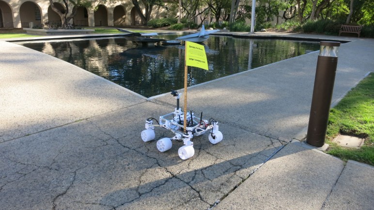
When it comes time for Ingenuity to demonstrate Mars helicopter technology, it will be dropped to the surface then wait for Perseverance to move a small distance away to prepare for the experiment. This arrangement is possible because the rover’s rocker-bogie suspension gave it more than enough ground clearance for a hitchhiking helicopter to ride along, holding on to the belly of the rover.

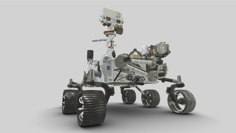
This ample ground clearance is also visible in the Mars 2020 Mission Identifier. The first I saw of this logo was on the side of the rocket payload aerodynamic fairing protecting the rover against the atmosphere during launch. I love this blocky minimalist design of the rover’s front view and believe this little logo hasn’t been used nearly enough.

Anyway, back to ground clearance: it is something obviously useful for a wheeled vehicle traversing off-road, which is desirable given the lack of roads on Mars. But raising the height of rover’s main body is only part of the equation, because it’s not the only thing that might collide with obstacles on the ground. We also have to worry about suspension components. This is something I noticed with JPL’s Open Source Rover design: if a ground obstacle is offset from a wheel, there’s a chance it will collide with aluminum structure. This picture uses a Roomba virtual wall marker to represent a rock on the ground, which is about to collide with suspension structure:

When I designed Sawppy, I thought I could improve upon this specific issue by taking advantage of the flexibility of 3D printing. I also chose Sawppy wheel motors with the requirement they must fit within the wheel with no protrusions. If Sawppy should encounter a Roomba virtual wall marker slightly offset from a wheel, there is no risk of collision:

I this was a pretty good Sawppy feature. However, after looking at how other Sawppy builders have customized their rovers, it appears this feature isn’t as valued as I thought it would be. There have been many Sawppy modifications that did not preserve this clearance.

For example, Marco Walther [mw46d] replaced wheel motors with much longer units that risks collision. He is aware of the risk, because he designed shielding to protect the motor encoders from damage. It’s a different approach, shielding vs. avoidance. Steve [jetdillo] adopted Marco’s design to good effect.

Chris Bond swapped out the wheels for RC monster truck wheels, similar to those used by JPL Open Source Rover. However, my wheel mounting arm design does not fit within the wheel. To compensate for this, Chris decided to push the wheels out. This leaves almost the entire wheel mounting arm out where it could collide with ground obstacles. It also means the steering axis is no longer aligned with the wheel, but Chris seems happy with his design so I guess it works well enough.

My lesson is that ground clearance isn’t as important as I thought it was. Or at least, not seen as important enough relative to features other builders wanted for their own rovers. This is valuable feedback for future iterations.

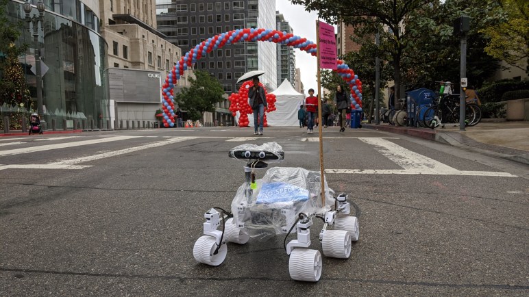
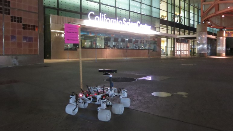
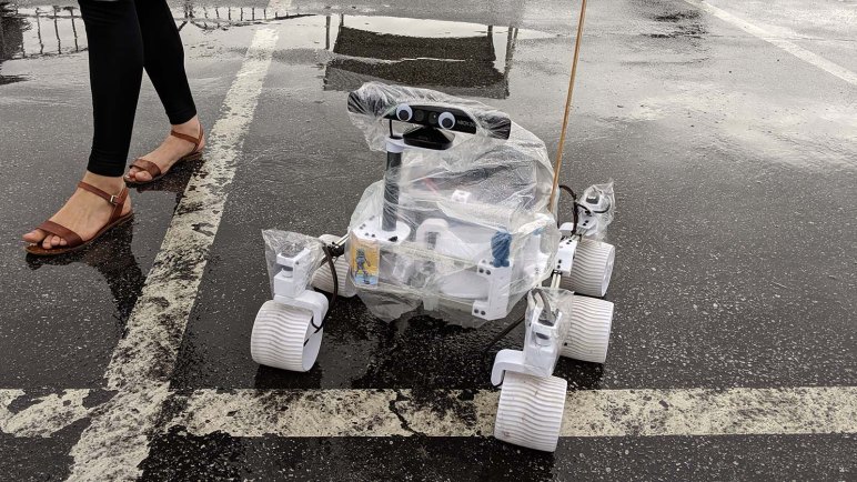
On the topic of rover iterations, I want to take a quick detour from my own rover to recognize some lesser-known counterparts to our robotic Mars explorers before returning to the topic of Sawppy builder feedback.

Perseverance Rover Interactive 3D Model

NASA released a 3D printable static display model of Mars rover Perseverance, which seems to have some improvements over the earlier Curiosity model. But that’s not the only 3D resource for the rover currently on its way to Mars. There is also a version designed for on-screen display rather than 3D printing.

Both the 3D printable (in STL file format) and 3D render (GLB file format) models were listed on the Mars 2020 rover page, which as of this writing has curiosity disappeared from the index page of NASA 3D resources. I’m not sure what’s going on there, but hopefully it’ll be fixed shortly.

When I listed 3D resources for Curiosity there was also a model suitable for 3D rendering. Available as download files for Blender the open source 3D graphics tool and as files embedded in a web page for interactive viewing. The latter is again available: The Mars 2020 mission page has a 3D model of Perseverance that we can interact within a web browser.

This browser interactive model is the most easily accessible version, there’s no need to install Blender or any other piece of software. It serves as an index page to many other pieces of information talking about the rover. While it has a lot of detail missing from the 3D printable model, it still has a few minor flaws. One of them I noticed only because I’ve been a fanatic of the rover: the online interactive rover’s right side wheels are reversed from the actual rover.

Perseverance, like Curiosity before it, has wheel spokes that are curved to absorb impact. I simplified the idea and translated it into a 3D-printable shape for Sawppy’s wheel. For both rovers, the direction of curvature for wheel spokes are the same for all six wheels, clearly visible in rover test footage. Shot in JPL’s vehicle assembly bay, we can see that the wheel spoke curvature is “clockwise” on all six wheels of Curiosity and Perseverance.

On the online interactive 3D model, its left side wheels match the real rover but its right side wheels had been flipped so the spokes point counter-clockwise.

It’s a tiny detail that would only be noticed by the most particular of rover fans, which I certainly am. Surprisingly, I’m not the only one! Because I’ve received questions about whether Sawppy’s wheels should be printed in mirrored orientation. Some Sawppy builders choose as I did, to have six identical wheels matching the real rover. Others chose to mirror three of the wheels as the web page interactive model did.

UPDATE: As one of the items leading up to (successful!) landing, the power team responsible for the radioisotope thermoelectric generator posted a different browser interactive 3D model online. This model is tailored more for engineering information than looking good, with components in false colors for contrast. But it is FAR more detailed, including wiring harnesses for wheel drive and steering motors. It also wins on accuracy in my book, as I see the wheel spokes are pointing in the correct direction.

And an extra bonus on this version: it includes Ingenuity, the first aircraft built by humans to fly in the atmosphere of another planet.

Built NASA’s Curiosity Rover 3D Printed Static Model

I’ve completed assembly of a 3D-printed static display model, released by NASA, of Mars rover Curiosity. It had a lot of details that were demanding when printed in PETG. In hindsight, I should have printed with PLA for fewer printing problems like stringing and overhangs. It is only a display model, it’ll just sit on a shelf and not stand out in the sun as Sawppy has done (and suffered for it.) Better dimensional accuracy with cleaner printing PLA would also help make the snap-together construction more effective. PETG is more ductile and so there wasn’t a “click” to announce successful assembly.

The demanding details were fitting for a static display model. Unlike its smaller sibling, this one is even poseable with corner wheels that steer and a robot arm that can articulate through the same degrees of freedom as the robot arm of the real thing.

With its emphasis on appearance, I was disappointed at the representation of my favorite feature of NASA JPL’s Mars Rovers: their rocker-bogie suspension. The first complaint is cosmetic: this model placed all three pair of wheels with the same track (distance between left and right wheels.) Curiosity’s front and rear wheel pairs actually have a narrower track than the middle pair, which I speculated was done that way so the suspension can fold up for flight. While a static model does not need to fold up for flight, it should at least accurately represent the layout.

The next complaint is a combination of cosmetic and functional: the suspension rockers do not articulate. Their angle is fixed relative to the body. On Curiosity, the left and right rockers are connected via the differential bar which keeps the two rockers in sync with complementary movement: if one moves up, the other moves down the same amount. But on this model, the differential is a surface feature and not a functional one, without connection to the suspension rocker.

On the upside, at least this model has articulation for suspension bogies. This was also missing from its smaller sibling. With articulating bogies, this rover model can at least pretend to handle rough terrain capability even if it lacks full rocker-bogie capability. In this picture, the middle wheel is raised by a piece of 3D-printed plastic I had on hand.

And finally, the suspension arms leading up to corner steering wheels have right-angle bends that are not an accurate representation of Curiosity’s suspension. I suspect this was done as a compromise to make these parts 3D-printable without supports, but it further reduces fidelity of this model.

There are several additional print problems with this first draft. If I were excited about this model I would reprint in PLA to see if it improves as expected. But given my lack of enthusiasm about representation of rocker-bogie suspension, I am content to stop here and look around for the next project.

NASA’s Curiosity Rover Model Print Cleanup and Assembly

NASA published a 3D printable static display model for Curiosity rover, and one of the things they offered to make printing easier are STL files that have already laid out many parts so they can be printed all at once. The upside is a lot less work on setup and less time tending to the printer. The downside is that if one part fails, it dooms the entire print.

The rover suspension parts are all in a single large multipart print. The real Curiosity rover suspension structure is cylindrical, and this model tries to maintain that shape, meaning there’s very little surface area contacting the print bed at the bottom of the cylinder. In the first few failed attempts, one of the suspension parts (and never the same one twice) would pop free from the print bed and wreck havoc.

To work around this, I told MatterControl to add a brim on all parts to increase surface contact area. It allowed the print to complete, but now I have to cut all those brims off before I could proceed to assembly.

I started by cleaning up the wheel hubs and pressing them into wheels.

Following my tradition of rover building, I proceeded to build a rover wheel on a stick.

Which quickly led to a rocker-bogie assembly for one side of the rover.

Unfortunately, the rocker does not articulate on this model. Its angle relative to the body is fixed. So this particular portion of the model is no more functional than the smaller version. However, the bogie does articulate, and all four of the corner wheels can steer.

Having built one side, it was easy to build the mirror side and put everything together. I noticed I had two extra steering brackets left over. Reviewing the large multipart print, I now notice there are six steering brackets even though only four rover wheels could steer. I shrug and move on.

Assembly of the robot arm was straightforward following the directions, leaving rover head installation as the final step. The static model is complete and I can admire it in its entirety.

3D Printing NASA’s Curiosity Rover Model

I decided to build the 3D printed Curiosity rover model released by NASA, and ran into some problems with print bed adhesion. Whoever designed this model had a 3D printer with better print bed adhesion than mine. My first few printed parts would lift from my print bed.

Some of this is unavoidable, the natural orientation of some parts dictate minimal surface area. The wheels, for example, have to sit with their narrow side edges on the bed because that is the only flat side. Fortunately wheels are round and produced minimal stress.

In contrast, the body of the rover is a large rectangular solid with sharp corners. This is a recipe for lifts and they released the STL files with some pre-generated brims to help the corners stick. Unfortunately that was not enough for me, because some of the corners still lifted off the print surface. Fortunately this was only a minor cosmetic issue, since the bottom does not need to be absolutely flat to mesh with any other part.

Another cosmetic issue is the radiothermal generator at the back, which ramped up more aggressively than my Pulse XE revision D printer could handle with PETG. Fortunately this is a bottom-facing surface and shouldn’t be too much of a detraction.

The wheel spokes were the most problematic with their fine detail requiring a lot of filament retraction as the print head moves from one tiny feature to another. In my experience, retraction-heavy prints work much better in PLA than PETG, in hindsight that’s what I should have used.

An interesting nod to convenience is that, in addition to publishing STL for individual parts, the creator of this project also included STL files with many parts laid out to be printed all at once. The upside is that there’s a lot less overhead. The downside is that failures can be troublesome.

NASA’s 3D Printable Curiosity Rover

When I take Sawppy out for some publicity, people frequently ask about the 3D printable Curiosity rover static model released by NASA. Some mistakenly thought Sawppy was the NASA-released design, others wanted to know how the rovers compared. I couldn’t answer the latter because I never printed the NASA rover, to the surprise of some, so I thought I should do it at least once.

NASA’s 3D printing resources page for a printable Curiosity points to a GitHub directory that actually has two printable models. I’ve seen the smaller one at a MatterHackers event, printed by another attendee who left her little rover on Sawppy’s table to keep my rover company.

The small model has limited articulation. All six wheels can roll, but cannot steer and it could only sit on a flat surface because its rocker-bogie suspension joints are fixed. I also noticed the robot arm joint articulation doesn’t match that of the real rover’s. Still, it is undeniably a representation of Curiosity and a cute little model.

Since I’ve seen the little one, I decided to skip it and try building the larger one. “Large” is relative, of course, it would still be much smaller than Sawppy. Another important difference is that it is an unmotorized static display model, which is actually the main reason I had not tried to build it. I wanted a rover that moved!

But I’m glad I’ve built it, because it was a good study into the different compromises this model made for the sake of being 3D printing friendly.

Sawppy Documentation: Change Preview and Other Notes

I am optimistic that one of the popular static site generators can help me reach my goals for an improved Sawppy documentation site. But the site generator itself is not enough, there are a few other details I’ll have to investigate. The primary one being ability to preview changes to pages earlier rather than later in the pipeline.

Today’s flow of editing markdown files can deliver immediate feedback because GitHub has a “Preview” tab on its built in Markdown editor. But once we’re no longer directly using GitHub’s simple Markdown transformation, we’ll lose that ability. Contributors should not be expected to set up a SSG environment on their computer in order to see the results of their work, and asking maintainers to review every change on their own SSG environment would not scale. (I say this using plural as if Sawppy has a big maintenance staff… it’s actually just me.)

The answer is to bring in tools from the continuous integration world, where tools exist to preview changes to a website before deploying live. Some use services like Netlify, which is not itself open source but there is a free tier available.

One example: look at the repository for Write the Docs website. Open one of the pending pull requests and click on “Show all checks”. One of them is “Read the Docs build succeeded!” and clicking “Details” will bring up a version of the site built with changes in the pull request. This is an interesting venue of investigation to learn more about.

This was the point where I ran out of steam, and the Write the Docs meeting ran out of time, but I have a big treasure trove of pointers to investigate and keep me busy for a while.

Other miscellaneous notes:

Sawppy Documentation Suggestion: Static Site Generators

I’m glad I had the chance to learn about terminology and tools of industrial-strength documentation. They are great for their respective niches, but adopting any of them would require major changes and I’m not ready to take such a big leap just yet. Which brings us to static site generators. (SSG) This category of software tools see a lot of open source development, giving us many options to choose from.

Background: As input, SSGs take content in various formats. A set of rules and templates are applied to that content, generating as output a set of HTML and CSS (and maybe JavaScript) files that can be served by any web server. “Static” in this context means the web server does not have to run any code to modify the files, they are transmitted directly to users’ web browsers as-is. (As opposed to a dynamic systems like PHP.)

A large number of SSGs accept Markdown as a text content input format, so Sawppy’s existing Markdown documentation could be used with small modifications rather than complete rewrites. This also preserves the advantages of using Markdown, meeting the ease-of-use challenges A and B.

Every SSG offers customization of the rules and templates that it applies to content. At the minimum there are themes for cosmetic appearance, but plugins and extensions allow more extensive functionality. This is where I hope to create something that meets my challenge C including a lightweight BOM tool. Around this point Eric spoke up that the JPL Open Source Rover documentation system has a script that generates parts list from document content, but the generated dependency tree is not exposed to the viewer. I want to build upon that precedent and also make this kind of information available to rover builders.

To be pedantic, Sawppy documentation is already using a SSG because GitHub does not display raw Markdown files. A simple transformation to HTML has been applied for display. However, the reason I started this investigation is because the simple GitHub transformation is very limited. GitHub is aware of this, and as an upgrade, has built-in support for a SSG called Jekyll for generating GitHub Pages.

As another example, most of us had experience reading technical software documentation on some subdomain of ReadTheDocs. All of these content were generated by a SSG. MkDocs and Sphinx are two popular SSGs for ReadTheDocs, and a lot of the default functionality (automatic indexing, references, etc.) useful for technical software documentation would be useful for Sawppy as well.

But features like a lightweight BOM tool would be outside the scope of software documentation, so there were several recommendations for investigating Hugo. It is apparently the current darling for flexibly transforming content (including Markdown text) into varying different presentations. Associated with Hugo is Docsy, a Hugo theme focused on technical documentation.

Hugo and Docsy would be a bigger step up in complexity than something like Jekyll, but I’m optimistic that the benefit will justify the cost. I plan to use that as my starting point and expand my experimentation from there. But they’ll only be a part of the solution, because no matter the static generator I use I will still want a way to preview changes.

Sawppy Documentation Suggestion: BOM and UML

I had the dream of a documentation system for Sawppy that doesn’t seem to fit anything out-of-the-box, but I had the chance to ask a group of documentation experts for what they thought might apply. It looks like DITA is the super flexible Swiss army knife for documentation. It is a free open standard, but the only freely available DITA software tool I could find works at a low level and I would have to put in a lot of time to build up the system I dream of. In addition, some of the problems I wanted to solve edge into other well-established problem areas.

Bill of Materials

Similar to documentation, the challenge of tracking parts and components is well-tread ground for engineering projects. People at the meeting with industry experience suggested a few terms. MRP or Materials Resource & Planning was one, plus several variants on BOM or Bill of Materials. This area is big business! Sadly free open source tools are scarce. Someone gave a pointer to OpenBOM.com but upon further research I was disappointed to find that despite the name, this tool is not actually open.

That leaves us with few choices between “use a spreadsheet” and big ticket enterprise software. Even if numerous choices were available, such tools are focused on a very small subset of the overall problem. I do want to set up some kind of parts management, but bringing in a full fledged BOM tool adds a lot of complexity I’m not sure is justified for a small scale project like Sawppy.

Model All The Things

I had the same concern about another series of suggestions: fully model everything about Sawppy using a modeling language like SysML or PlantUML. I agree doing so will result in a complete picture, breaking down every part of the rover project. Such data could then feed into software packages that generate visualizations plotting dependencies between components. That sounds good, but the amount of work also felt disproportionate to the benefit it would bring to a project of this scale.


What I hoped would be a better fit for a project of Sawppy’s scale are the documentation systems already available for open-source software projects. While they would not have some of the hardware-focused features — such as BOM or UML above — they are more approachable than DITA and promise to be amenable to customizations. Perhaps even to give a lightweight subset of big BOM and UML tools.

Sawppy Documentation Suggestion: DITA

I outlined my Sawppy project and the challenges I want to tackle to the combined Write the Docs LA/SGVLUG meetup on the evening of October 8th. Sawppy’s current system of a loose set of Markdown files score highly on ease of contribution (challenge A) and ease of management (challenge B), but fall flat on querying dependencies (challenge C). What can I look into that helps improve information presentation without giving up the rest?

Fundamentally speaking, challenge C is not new, as it would be desirable in any large scale engineering project. The novel twist here is the desire to do it all with a system that is inviting for public contribution. As a general rule, documentarians for large engineering projects are professionals who have undergone training and have licenses for proprietary software tools.

DITA

Most such tools are excluded from consideration due to cost, but many of them deal with DITA, an open XML-based data model for authoring and publishing under the custody of the OASIS consortium. It is the standard answer to reassure customers wary of being locked in to proprietary file formats. And since it is an open format, there exists a DITA Open Toolkit to transform DITA data to desired output formats… HTML, PDF, even Markdown! There are learning resources at https://learningdita.com/

As a XML (and thus text) based format, DITA would be GitHub friendly for branching and merging. It is very flexible for creating any organization we want (creating a “Subject Schema” for DITA) but taking advantage of that power will take work. DITA Open Toolkit functions at a lower level relative to the other tools discussed later. A quick web search found many commercial offerings built on DITA (example: https://easydita.com/) but failed to find free open source counterpart.

So DITA is powerful, but that power comes at a cost, and I’ll have to decide if the cost/benefit analysis comes out in favor. This also applies to several other professional documentation concepts.

Sawppy Documentation System Challenges

I want to improve the usability of Sawppy documentation. Keeping in mind some example problems I want solved I started my quest. To find a system to document and track these types of relationships, without losing too much of the advantages of my current system. This means every candidate system must meet the following challenges:

Challenge A: Easy to Contribute

When a Markdown file is hosted on GitHub, a potential contributor can click the “Edit” button to create a fork of the repository, make a quick fix, and create a pull request all via GitHub website. This presents an extremely low barrier to entry for contributors which is a feature I want to preserve. If contributors were required to install and learn some piece of documentation software, that would discourage many people from participating before we even talk about the learning curve for that software.

Challenge B: Easy to Manage

When using GitHub’s web interface to edit a Markdown file, visualizing the change is as simple as clicking over to the “Preview” tab of the editor. Sadly such ease can’t be matched by any system external to GitHub, but it would be nice to have some way to let a contributor see what the end results look like. Failing that, I must have a way to visualize the final impact of changes before I merge a pull request. It is unacceptable to not see changes until after merging into the main branch.

Challenge C: Easy to Query

The desired documentation system will take metadata written by document author and build an interactive presentation. This way rover builders can find information without being constrained by the current linear narrative. Here are some examples of questions I’ve received for Sawppy, rephrased in terms of wheel axle.

  • (Easy: positive query) I’m on the wheel hub assembly page, and it needs the wheel axle which I guess I forgot to build. Where do I need to go?
  • (Hard: negative query) My order of 8mm shafts got delayed. What can I work on now that’s not dependent on having these shafts?
  • (Both of above) How can a teacher most effectively divide up rover tasks so multiple students teams can build the rover in parallel?

Challenge D: Free

It would be nice for the system to be free as in freedom, but at the very least it must be free as in beer. Design for Sawppy is given away at no cost to rover fans everywhere, there is no profit to cover monetary expense of a commercial documentation system.

Once I laid out these challenges to the group and opened the meeting to discussion, people started offering suggestions. Some professional documentarians brought up DITA as a venue for investigation.

Sawppy Documentation Shortcoming Example: Wheel Axles

To illustrate problems with Sawppy’s documentation, I’ll use a single component as example: Sawppy wheel axle. There are at least three entirely separate pages relating to the wheel axle:

  1. The page of parts list, telling a builder to buy 8mm metal shaft.
  2. The page for 8mm shaft modification, where I describe how to cut the long shaft into shorter segments. Followed by steps to turn these segments into wheel axles. Other segments were turned into steering shafts, plus those turned into rocker-bogie suspension pivots.
  3. The page for wheel hub assembly, which incorporates a single segment of the 8mm wheel axle shaft.

While these three files were all linked from the index page, there’s no obvious way to retrieve the relationship between them in the context of wheel axles. I can manually add links between them, but this is time consuming and perpetually incomplete. Even worse, as the number of relationships grew, it will quickly become a maintenance nightmare.

Thus I started my quest to find a system to document and track these types of relationships without losing (too much) of the advantages of my current system.

Sawppy Documentation Could Be Better

When I decided to release Sawppy to the world, I thought briefly about how to best organize all the information I want to convey for rover assembly. I quickly fell into a state of Analysis Paralysis and, as a path out of that state, decided that it was better to have something written down whatever the format. No matter how unorganized, is still better than keeping it all in my head.

I first tried putting it in the “Build Instructions” section of Sawppy’s Hackaday.io page, but that feature has some strange and unpredictable limitations that became annoying as the length of instructions grew. The final straw was when I noticed that images and instructions for earlier steps were disappearing as I added later steps. That made me… unhappy, so I went to something else.

The second attempt is what I have as of today: a loose collection of Markdown files on a Github repository. Edited in a code editor rather than a word processor, I struggled with typos and grammatical errors as I lacked the usual automated proofreading tools present in a word processor. Still, with a large helping of assembly pictures, it was just barely enough to help other people build their own rovers.

I was painfully aware of the fact there is a ton of obvious room for improvement. This was just the “get it written down” first stage and at some point I need to revisit the various problems still open. The most significant of which is lack of structure beyond an index page with links to all the other pages. The index suggested a relative ordering that matched my personal assembly order, but that doesn’t necessarily work for anyone else. And worse, they would be stuck if they wanted to ask some specific questions my layout is unable to answer.

Cardboard Absurdity: Sexy Minion

I abandoned the first draft of my cardboard Mike Wazowski for another attempt later, but I did not abandon my other Hallowing. An idea to put it to use came courtesy of Emily’s reply to my cardboard minion tweet.

This “sexy minion” is certainly not something I would have found on my own, and my initial reaction was probably what Emily intended: vaguely disturbed and resignation to the fact I can’t un-see that image.

But it’s on Twitter now, and it’s also in my brain now, and I do have an extra Hallowing on hand, so I decided to play along with the joke with a minimum-effort project. I imported the image into a photo editor and scaled it so the eye is the right size to use with a Hallowing. Fortunately it fit on a sheet of standard letter-sized paper so I didn’t have to crop any part of it off.

I tried to print it on my color inkjet printer, but that thing hasn’t printed anything in months (possibly years) so naturally its print nozzles were clogged. A standard unclog routine did not fix it and I didn’t want to spend time troubleshooting. (Remember: minimal effort.) So I printed on my monochrome laser printer and colored it in manually afterwards using markers.

Given the minimal effort I didn’t try to trace the outline curves with my new favorite cardboard tool the Canary knife, just a rectangular piece of cardboard and the marker-colorized paper taped on top. My X-Acto blade made quick work of the eyehole, and the second Hallowing was taped in place. I set it up my convertible photo studio for a quick video and threw it up on Twitter.

This silly little project couldn’t have taken more than half an hour (even less if I subtract fussing with the clogged inkjet) and it turned out to be unexpectedly (or is that disturbingly?) popular. As a result I have the sinking feeling this is not the last I’ve seen of “sexy minion”.

I also felt a bit bad that I didn’t put in the time to research where that drawing came from. It wasn’t a big deal when I thought it’d just be a throwaway joke between friends, but with thousands of views the artist’s name should have been attached. I can’t edit my original tweet, but I could at least credit the artist @nicoisesalade here:

Cardboard Companion: Mike Wazowski

My trial run using a Canary cardboard cutter was far more successful than I had expected, resulting in a little cardboard companion minion perched on my shoulder. I was extremely happy and joined this month’s (Virtual) Wearables Wednesdays event at CRASHSpace to show off my minion as a wearable electronic project. And also to thank Barb (who usually attends the event) for telling me about the Canary cutter.

Barb immediately (and correctly) recognized the minion’s eye as the Adafruit HalloWing default program. She had several sets of similar eyes on hand, some incorporated into projects, but all the units within reach came as pairs so there were no immediate advice on how to get my two units to synchronize. But by now I didn’t really want to synchronize them anyway, because that would mean taking apart my minion which I’m not ready to do just yet.

So I asked the attendees what I should do with the other eye. People started brainstorming and tossing out ideas. They were fine ideas but they didn’t capture me as much as when Liz said “Mike Wazowski”. I said “Yes!” and got started immediately while the meeting was still underway. This is falling back on old patterns, as it is pretty typical for work to happen during non-virtual Wearables Wednesdays meet.

I found a picture of Mike Wazowski on the internet and traced out a rough outline on cardboard. For the minion I wanted to keep the eyehole small so none of the electronics are visible. For Mike I thought I’d explore how things looked if the eye hole was larger.

Once I had Mike cut out and popped my second HalloWing into the eyehole, I decided I did not like how it looked. I much preferred the minion approach where the circuit board was hidden. If I wanted to build a Mike Wazowski with a properly obscured HalloWing eye hole while still maintaining proportions, I will need to cut a smaller Mike. There’s also a second reason to want a smaller Mike: this one is too wide to sit properly on my shoulder. Maybe someone with much broader shoulders can pull it off, but this Mike’s butt is too wide for me to carry around.

I will abandon this cardboard cutout and stick “try again with smaller Mike” on the to-do list. This is the beauty of experimenting with cardboard: cost of failure is low, and speed of iteration is fast. I could very quickly follow up this abandoned project with an absurd project.

Cardboard Companion: Minion

I’ve long admired the robot companions built by Alex Glow and Odd Jayy but never dedicated the time and effort to build a good one of my own. I still haven’t done so… but I’ve spent roughly an hour or two to build a low-effort companion out of cardboard.

This project was kicked off when I was moving a few boxes around and noticed the Hallowing I received at Supercon 2018 almost two full years ago. When I wrote about it earlier I thought it had full of promise and should be a lot of fun to play with. That is still true, it just never came to the top of my priority list. I actually have two of them now, as Emily gave me hers saying she’d never do anything with it. I said I would definitely find something fun to do but nothing had happened since.

So when I saw them again, I had an urge to do something with them right now. Today. The pair of Hallowing deserved to be dusted off, literally and figuratively. If I can’t do something unique and cool, I can at least do something to verify at least they still function.

When I plugged them into a USB power bank, they started right up. A good start!

I thought I’d use them both by following Adafruit’s instructions to synchronize two of them. Unfortunately I made a mistake somewhere and the two eyes remained stubbornly independent. So I switched to a backup plan: what do I know that has a single eye? The first one that came to my mind is a minion from the movie Despicable Me.

I made a rough sketch and cut out the shape of a minion. I wanted the minion to sit on my shoulder, so the outline was placed such that the existing fold for this box lid is roughly at the (not terribly well defined) waist of the minion. The cutting tool visible in this picture is a Canary corrugated cardboard cutter. This was my first time using it and I am now a big fan.

After I cut out the eyehole, a quick size comparison test confirmed it was in the ballpark. I decided to stop cutting at this point. A hole that’s slightly too small like this will obscure a portion of the eye, not a big deal. In contrast a hole that’s slightly too big will show the wires at the edge of this LCD module or the circuit board underneath, either of which would spoil the look and thus something I wanted to avoid.

A black marker helped make the cardboard look more like a minion.

The minion’s work overalls courtesy of blue highlighter marker.

I used cardboard to build a tripod to help the minion sit on my shoulders, but it is top-heavy with the Hallowing and prone to falling over. I decided to tape some magnets to the bottom of the minion.

Once I set the minion on my shoulder, I could install matching magnets inside my shirt. The two magnets pinch fabric of my shirt, holding the minion in place.

Voila! A low effort cardboard companion.

It only scratches the surface of what the Hallowing can do, but far better than just letting it gather dust. Will it find a place in a cooler and more sophisticated project? Check back in two years!

Samsung 500T Unexpected Power Consumption Caused By Patch Tuesday

I’ve set up my unloved Samsung 500T tablet to display the current position of the International Space Station around the clock. This was a very steady and predictable workload for the machine, which made it the perfect solar power test subject. Since the time I devised a first draft of a strategy for maximize solar power runtime, I’ve been tweaking it as I go.

The tablet has behaved predictably over several weeks, so I could test different times to connect/disconnect from the solar panel and maximize storage time while also keeping the battery state of charge between 20% and 80% to maximize its cycle life. It’s not a very precise experiment on my end because I’ve been connecting and disconnecting power manually. An automated solution is in the future, once I’ve figured out what I want to do.

Things were going well until Tuesday of this week, when my power scheme went awry. First problem was that I neglected to disconnect power when it reached 80% SoC, that was on me. But then I ran into a second problem: the power consumption was extremely erratic after I disconnected power to the tablet (area highlighted in red.) As far as I knew, I did nothing to trigger any change in behavior, and the tablet isn’t displaying anything other than the ESA ISS Tracker. What’s going on?

The keyword is “Tuesday”, more specifically, it is the second Tuesday of the month when Microsoft pushes out security updates for Windows. On my other Windows computers, Patch Tuesday takes only a few minutes to download and install. But the Samsung 500T is so slow, patch installation is a drawn-out multi-hour affair. During which it consumes significantly more power than just displaying the ESA ISS tracker.

This episode reminds me of the value of long term testing, and that my Samsung 500T solar power strategy will need to allocate more power on the second Tuesday of the month.

Out with the Lead-Acid, In with the Lithium-Ion.

A little over two and a half years ago, I bought a Monoprice PowerCache 220 (Item #15278) to help store power generated by my cheap Harbor Freight solar array and also to utilize that power by the way of AC inverter and USB power converters. When new, the PowerCache was quite capable of gathering up the day’s solar generation and using that energy to charge various battery-powered devices around the house. Up to and including charging an Apple MacBook Air (2014).

I expected this battery to wear down, I just didn’t know how quickly. Battery University has a capacity loss chart, but that is for lead acid batteries held on standby for long periods of time (like in an UPS) showing the capacity would fade to about 85% after two and a half years. However, this battery was cycled on a daily basis for most of the past 2+ years. And while the charge controller does perform an occasional top-off charge, it’s probably not as much as the battery desires.

As a result of this stressful usage pattern, the battery inside my PowerCache 200 has degraded to a point where it could barely hold enough energy to charge a cell phone. That by itself was not a disaster, as I had anticipated battery degradation and was prepared to revive the machine with a new lead-acid battery. Unfortunately the machine has developed another problem: the thermal protection system has gone amok. Within five minutes of the PowerCache starting up (when everything is still room temperature) the “overheating” warning triangle starts blinking and soon the thermal protection routine kicks in and shuts everything down.

So instead of shopping for a replacement lead-acid battery for the PowerCache 220, I started looking at replacing it entirely. I was pleasantly surprised to see that the cost of lithium based batteries have dropped significantly within the past two and a half years. As of right now, lead-acid based systems are still cheaper, but the price premium for going lithium-ion is now small enough to convince me to make the switch. I’ll pay a little extra, but I’ll get something that’s far smaller and lighter. Thus I bought a Paxcess Rockman 200 Portable Power Station (*) to see how it handles my usage scenarios.

[UPDATE: I opened up the PowerCache 220 with the intent to fix it, but things took an ugly turn and ended up as a full teardown.]


(*) Disclosure: As an Amazon Associate I earn from qualifying purchases.

Adding Noble Specified Hardware Failed To Enable BLE Discovery

I’ve known Bluetooth Low Energy (BLE) to be a new technology that can still be challenging to interface with. I’ve had success so far with Node-RED making hard things easy, most recently in reading battery power state in an old Windows 10 laptop. So I wanted to see if BLE can be just as easy. The answer: it was not. Getting node-red-contrib-noble-bluetooth set up and launching a flow was easy, but attempting to discover nearby BLE devices caused Node-RED itself to crash.

No compatible USB Bluetooth 4.0 device found!

Looking at the crash stack, the culprit appears to be Noble, the Node.js BLE module upon which the Node-RED extension was built. There are some native code components that were built for Noble support, and if things go sour in native code, it fails like native code, hence the jarring failure. Quite unlike the typical recoverable JavaScript exception I’ve become spoiled by.

Searching on that error message, I found more information in this GitHub issue filed against Noble, which pointed to a Noble document explaining that support is limited to a fixed list of hardware. Not surprisingly, the chip on board my experimental laptop was not on the list. I searched for the hardware on that list, and thought the Asus USB-BT400 (*) was cheap enough to order and give it a try.

For the BT400 to function under Noble, I also needed to circumvent the normal driver installation process and instead install WinUSB so Noble can directly access the hardware to bypass Windows’ Bluetooth stack. The WinUSB installation link in Noble Wiki is dead, but a web search pointed to this link as the modern replacement.

Once WinUSB driver was installed for the Asus USB-BT400 Bluetooth adapter, Noble was able to find it and didn’t crash when I attempted to discover nearby BLE devices. Unfortunately, neither did it find any of the BLE hardware I had on hand for this test. I had hoped that, even if I couldn’t use that hardware, I could at least discover their presence.

This test was not a success, ah well. Life moves on to other experiments.


(*) Disclosure: As an Amazon Associate I earn from qualifying purchases.

Initial Solar Power Strategy for Samsung 500T

I foresee a lot of refinement ahead for optimizing how to run my Samsung 500T (displaying ESA ISS tracker) on solar power as much as possible using its internal battery. But I have to start somewhere, thus this first plan as starting point.

To improve battery cycle life, I want to keep its state of charge (SoC) between 20% and 80% which should be fairly straightforward to put into a program. That’s just the easy part, the harder part is optimizing for solar power by trying to keep the charging periods as much as possible during times when panels are delivering energy. And it wouldn’t be possible do use internal battery capacity around the clock because that “middle 60%” of the battery is not enough to take the tablet all the way through the night. So it will need to draw upon the lead-acid array sometime overnight but that should be kept as low as possible.

Accomplishing this goal will require optimizing for both ends of the period when solar power is available. In the late afternoon, power should be connected to get up to 80% SoC just as the sun goes down, which requires knowing when sunset will be. During the late-night feeding, the tablet should be given just enough power to leave it at 20% SoC when the sun is back up, which requires knowing when sunrise will be. Add to this seasonal variability other random factors like rainy days, and we have a pretty complex power management challenge on our hands.

Right now 60% of power can keep the tablet running for approximately 9 hours, a number that I expect to shrink as the battery degrades in the future. That inevitable degradation is, in fact, part of the experiment! But right now that means we need a little less than three discharge-charge cycles per day. According to cycle life chart at Battery University, 80% SoC is near the optimal trade off point between cycle life and capacity. But if don’t need three full cycles, we can prolong battery cycle life even further by charging to some level less than 80%, just enough to make it to the next event.

With those considerations, here’s the initial daily charging plan:

  1. The most important cycle is the one just before sunset bringing the battery up to 80%. This maximizes the solar energy captured for running when there’s no direct solar energy.
  2. The following charging cycle will occur sometime overnight. It does not need to get all the way up to 80%, the goal is to give the tablet just enough to leave it with 20% by the time solar panels are delivering power again. When should this charging cycle start and where it should end is yet to be determined.
  3. After the sun starts shining, we’ll need another charging cycle to bring the battery back up via solar power. Ideally we charge up to 80% SoC and stay there until sunset, but we don’t have the means to control that. So we’ll charge just enough to leave us with 20% by the time of the sunset charge (#1 above).

Depending on the amount of sun available, charge cycles #2 and #3 should halt before reaching 80%, which should help prolong battery life. This plan was my starting point to run a multi-week experiment using different strategies, as well as finding unexpected perturbations I’ll have to account for.