Sawppy Odometry Candidate: Flow Breakout Board

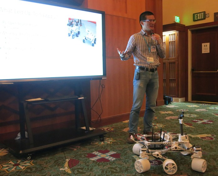
When I presented Sawppy the Rover at Robotics Society of Southern California, one of the things I brought up as an open problems is how to determine Sawppy’s movement through its environment. Wheel odometry is sufficient for a robot traveling on flat ground like Phoebe, but when Sawppy travels on rough terrain things can get messy in more ways than one.

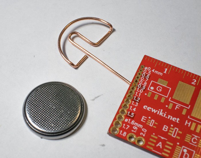
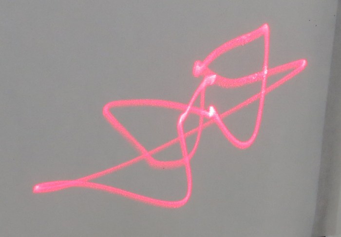
In the question-and-answer session some people brought up the idea of calculating odometry by visual means, much in the way a modern optical computer mouse determines its movement on a desk. This is something I could whip up with a downward pointing webcam and open source software, but there are also pieces of hardware designed specifically to perform this task. One example is the PWM3901 chip, which I could experiment using breakout boards like this item on Tindie.

However, that visual calculation is only part of the challenge, because translating what that camera sees into a physical dimension requires one more piece of data: the distance from the camera to the surface it is looking at. Depending on application, this distance might be a known quantity. But for robotic applications where the distance may vary, a distance sensor would be required.

As a follow-up to my presentation, RSSC’s online discussion forum brought up the Flow Breakout Board. This is an interesting candidate for helping Sawppy gain awareness of how it is moving through its environment (or failing to do so, as the case may be.) A small lightweight module that puts the aforementioned PWM3901 chip alongside a VL53L0x distance sensor.

flow_breakout_585px-1

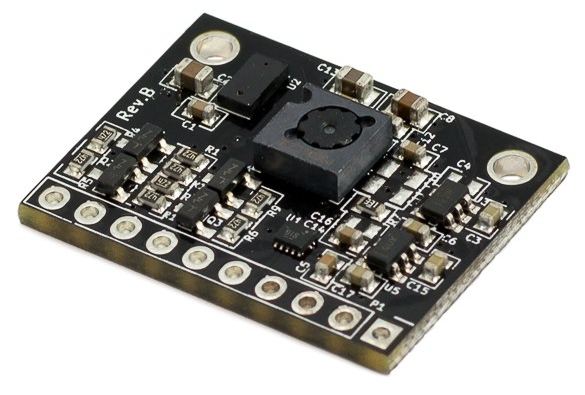
The breakout board only handles the electrical connections – an external computer or microcontroller will be necessary to make the whole system sing. That external module will need to communicate with PWM3901 via SPI and, separately, VL53L0x via I2C. Then it will need perform the math to calculate actual X-Y distance traveled. This in itself isn’t a problem.

The problem comes from the fact a PWM3901 was designed to be used on small multirotor aircraft to aid them in holding position. Two design decisions that make sense for its intended purpose turns out to be a problem for Sawppy.

  1. This chip is designed to help hold position, which is why it was not concerned with knowing the height above surface or physical dimension of that translation: the sensor was only concerned with detecting movement so the aircraft can be brought back to position.
  2. Multirotor aircraft all have built-in gyroscopes to stabilize itself, so they already detect rotation about their Z axis. Sawppy has no such sensor and would not be able to calculate its position in global space if it doesn’t know how much it has turned in place.
  3. Multirotor aircraft are flying in the air, so the designed working range of 80mm to infinity is perfectly fine. However, Sawppy has only 160mm between the bottom of the equipment bay and nominal floor distance. If traversing over obstacles more than 80mm tall, or rough terrain bringing surface within 80mm of the sensor, this sensor would become disoriented.

This is a very cool sensor module that has a lot of possibilities, and despite its potential problems it has been added to the list of things to try for Sawppy in the future.

Give The People What They Want: Wire Straightener Now On Thingiverse

My wire straightener project was focused on simplicity and reliability. There are no mechanical adjustments for different gauge wires or to correct for a 3D printer’s dimensional accuracy (or lack thereof.) Every adjustment had to be made in CAD by changing the relevant dimensions and printing a test unit. This requires more work up front, but once all the dimensions are dialed in, the single piece tool will never fall apart and will never need readjustment.

spool holder with two stage straightener 1600x1200

It also means the raw STL files generated by Onshape for my printer would probably not work properly for anyone else. For starters, it was tailored for my specific spool of 18 gauge copper wire. According to Google, 18 gauge translates to a diameter of 1.02mm. My calipers say my spool is 1.00 +/- 0.01 mm, slightly smaller than specified. It is then processed into G-Code by Simplify3D, my printing slicer. And finally that G-Code is translated into plastic by my printer, with all its individual quirks.

So while I was happy to share my Onshape CAD file, I resisted sharing the STL because it almost certainly would not work correctly and I don’t want people to have a bad experience with my design. But people ask for it anyway, over and over.

I have since changed my mind on the topic of posting the STL. I will post the STL, but never by itself. I will also post information describing why the STL is probably not going to work, link to Onshape CAD, and what people need to do to make their own. I foresee the following possibilities:

  1. People who don’t read the instructions will print the file as-is:
    • If it works for them – great!
    • If it doesn’t:
      • Abandon with “This design is stupid and it sucks.” – Well, let’s face it, I was not going to reach this audience anyway.
      • Maybe I should go back and read the instructions.”
  2. People who read the instructions:
    • Successfully fine-tune parameters to successfully make their own straightener – great!
    • Tried to follow directions, but encountered problems and need help – I’m happy to help.

Unless I’ve failed to consider something horrible, these possibilities have more upsides than downsides, so let’s try it. I’m going to share the STL files on the Hackaday.io project page, and I’ve created a Thingiverse page for it as well.

(Cross-posted to Hackaday.io)

ROS In Three Dimensions: Navigation and Planning Will Be Hard

backyard sawppy 1600At this point my research has led me to ROS modules RTAB-Map which will create a three dimensional representation of a robot’s environment. It seems very promising… but building such a representation is only half the battle. How would a robot make good use of this data? My research has not yet uncovered applicable solutions.

The easy thing to do is to fall back to two dimensions, which will allow the use of standard ROS navigation stack. The RTAB-Map ROS module appears to make the super easy, with the option to output a two dimension occupancy grid just like what navigation wants. It is a baseline for handling indoor environments, navigating from room to room and such.

But where’s the fun in that? I could already do that with a strictly two-dimensional Phoebe. Sawppy is a six wheel rover for handling rougher terrain and it would be far preferable to make Sawppy autonomous with ROS modules that can understand and navigate outdoor environments. But doing so successfully will require solving a lot of related problems that I don’t have answers yet.

We can see a few challenges in the picture of Sawppy in a back yard environment:

  • Grass is a rough surface that would be very noisy to robot sensors due to individual blades of grass. With its six wheel drivetrain, Sawppy can almost treat grassy terrain as flat ground. But not quite! There are hidden dangers – like sprinkler heads – which could hamper movement and should be considered in path planning.
  • In the lower right corner we can see transition from grass to flat red brick. This would show as a transition to robot sensors as well, but deciding whether that transition is important will need to be part of path planning. It even introduces a new consideration in the form of direction: Sawppy has no problem dropping from grass to brick, but it takes effort to climb from brick back on to grass. This asymmetry in cost would need to be accounted for.
  • In the upper left corner we see a row of short bricks. An autonomous Sawppy would need to evaluate those short bricks and decide if they could be climbed, or if they are obstacles to be avoided. Experimentally I have found that they are obstacles, but how would Sawppy know that? Or more interestingly: how would Sawppy perform its own experiment autonomously?

So many interesting problems, so little time!

(Cross-posted to Hackaday.io)

ROS In Three Dimensions: Data Structure and Sensor

rosorg-logo1One of the ways a TurtleBot makes ROS easier and more approachable for beginners is by simplifying a robot’s world into two dimensions. It’s somewhat like the introductory chapters of a physics textbook, where all surfaces are friction-less and all collisions are perfectly inelastic. The world of a TurtleBot is perfectly flat and all obstacles have an infinite height. This simplification allows the robot’s environment to be represented as a 2D array called an occupancy grid.

Of course, the real world is more complicated. My TurtleBot clone Phoebe encountered several problems just trying to navigate my home. The real world do not have flat floors and obstacles come in all shapes, sizes, and heights. Fortunately, researchers have been working on problems encountered by robots venturing outside the simplified world, it’s a matter of reading research papers and following their citation links to find the tools.

One area of research improves upon the 2D occupancy grid by building data structures that can represent a robot’s environment in 3D. I’ve found several papers that built upon the octree concept, so that seems to be a good place to start.

But for a robot to build a representation of its environment in 3D, it needs 3D sensors. Phoebe’s Neato vacuum LIDAR works in a simplified 2D world but won’t cut it anymore in a 3D world. The most affordable entry point here is the Microsoft Kinect sensor bar from an old Xbox 360, which can function as a RGBD (red + blue + green + depth) input source for ROS.

Phoebe used Gmapping for SLAM, but that takes 2D laser scan data and generates a 2D occupancy grid. Searching for a 3D SLAM algorithm that can digest RGBD camera data, I searched for “RGBD SLAM” that led immediately to this straightforwardly named package. But of course, that’s not the only one around. I’ve also come across RTAB-Map which seems to be better maintained and updated for recent ROS releases. And best of all, RTAB-Map has the ability to generate odometry data purely from the RGBD input stream, which might allow me to bypass the challenges of calculating Sawppy’s chassis odometry from unreliable servo angle readings.

(Cross-posted to Hackaday.io)

Sawppy on ROS: Open Problems

A great side effect of giving a presentation is that it requires me to gather my thoughts in order to present them to others. Since members of RSSC are familar with ROS, I collected my scattered thoughts on ROS over the past few weeks and condensed the essence into a single slide that I’ve added to my presentation.

backyard sawppy 1600

From building and running my Phoebe robot, I learned about the basics of ROS using a two-wheeled robot on flat terrain. Sticking to 2D simplifies a lot of robotics problems and I thought it would help me expand to a six-wheeled rover to rough terrain. Well, I was right on the former but the latter is still a big step to climb.

The bare basic responsibilities of a ROS TurtleBot chassis (and derivatives like Phoebe) is twofold: subscribe to topic /cmd_vel and execute movement commands published to that topic, and from the resulting movement, calculate and publish odometry data to topic /odom.

Executing commands sent to /cmd_vel is relatively straightforward when Sawppy is on level ground. It would not terribly different from existing code. The challenge comes from uneven terrain with unpredictable traction. Some of Sawppy’s wheels might slip and resulting motion might be very different from what was commanded. My experience with Phoebe showed that while it is possible to correct for minor drift, major sudden unexpected shifts in position or orientation (such as when Phoebe runs into an unseen obstacle) throws everything out of whack.

Given the potential for wheel slip on uneven terrain, calculating Sawppy odometry is a challenge. And that’s before we consider another problem: the inexpensive serial bus servos I use do not have fine pitched rotation encoders, just a sensor for servo angle that only covers ~240 of 360 degrees. While I would be happy if it just didn’t return any data when out of range, it actually returns random data. I haven’t yet figured out a good way to filter the signal out of the noise, which would be required to calculate odometry.

And these are just challenges within the chassis I built, there’s more out there!

(Cross-posted to Hackaday.io)

Sawppy Presented at January 2019 RSSC Meeting

Today I introduced my rover project Sawppy to members of Robotics Society of Southern California. Before the presentations started, Sawppy sat on a table so interested people can come by for a closer look. My visual aid PowerPoint slide deck is available here.

sawppy at rssc

My presentation is an extended version of what I gave at Downtown LA Mini Maker Faire. Some of the addition came at the beginning: this time I’m not following a JPL Open Source Rover presentation, so I had to give people the background story on ROV-E, JPL OSR, and SGVHAK rover to properly explain Sawppy’s inspiration. Some of the addition came at the end: there were some technical details that I was able to discuss with a technical audience. (I’ll expand on them in future blog posts.)

I was very happy at the positive reception I received for Sawppy. The first talk of the morning covered autonomous robots, so I was afraid the audience would look down at Sawppy’s lack of autonomy. Thankfully that did not turn out to be a big deal. Many were impressed by the mechanical design and construction. Quite a few were also appreciative when I stressed my emphasis on keeping Sawppy affordable and accessible. In the Q&A session we covered a few issues that had easy solutions… if one had a metalworking machine shop. I insisted that Sawppy could be built without a machine shop, and that’s why I made some of the design decisions I did.

A few people were not aware of Onshape and my presentation stirred their interest to look into it. There was also a surprising level of interest in my mention of Monoprice Maker Select v2 as an affordable entry level 3D printer, enough hands were raised that I signed up to give a future talk about my experience.

(Cross-posted to Hackaday.io)

Dell Alienware Area-51m vs. Luggable PC

On the Hackaday.io project page of my Luggable PC, I wrote the following as part of my reason for undertaking the project:

The laptop market has seen a great deal of innovation in form factors. From super thin-and-light convertible tablets to heavyweight expensive “Gamer Laptops.” The latter pushes the limits of laptop form factor towards the desktop segment.

In contrast, the PC desktop market has not seen a similar level of innovation.

It was true when I wrote it, and to the best of my knowledge it has continued to be the case. CES (Consumer Electronics Show) 2019 is underway and there are some pretty crazy gamer laptops getting launched, and I have heard nothing similar to my Luggable PC from a major computer maker.

laptops-aw-alienware-area-51m-nt-pdp-mod-heroSo what’s new in 2019? A representative of current leading edge gamer laptop is the newly launched Dell Alienware Area-51m. It is a beast of a machine pushing ten pounds, almost half the weight of my luggable. Though granted that weight includes a battery for some duration of operation away from a plug, something my luggable lacks. It’s not clear if that weight includes the AC power adapter, or possibly adapters plural since I see two power sockets in pictures. As the machine has not yet officially launched, there isn’t yet an online manual for me to go read what that’s about.

It offers impressive upgrade options for a laptop. Unlike most laptops, it uses a desktop CPU complete with a desktop motherboard processor socket. The memory and M.2 SSD are not huge surprises – they’re fairly par for the course even in mid tier laptops. What is a surprise is the separate detachable video card that can be upgraded, at least in theory. Unlike my luggable which takes standard desktop video cards, this machine takes a format I do not recognize. Ars Technica said it is the “Dell Graphics Form Factor” which I had never heard of, and found no documentation for. I share Ars skepticism in the upgrade claims. Almost ten years ago I bought a 17-inch Dell laptop with a separate video card, and I never saw an upgrade option for it.

There are many different upgrade options for the 17″ screen, but they are all 1080p displays. I found this curious – I would have expected a 4K option in this day and age. Or at least something like the 2560×1440 resolution of the monitor I used in Mark II.

And finally – that price tag! It’s an impressive piece of engineering, and obviously a low volume niche, but the starting price over $2,500 still came as a shock. While the current market prices may make more sense to buy instead of building a mid-tier computer, I could definitely build a high end luggable with specifications similar to the Alienware Area-51m for less.

I am clearly not the target demographic for this product, but it was still fun to look at.

Sawppy Will Be Presented At RSSC

Roger Sawppy

I brought Sawppy to the Downtown Los Angeles Mini Maker Faire this past December, where I had the opportunity to give a short presentation about my project. (Above.) Also at the event were the Robotics Society of Southern California (RSSC) and a few members asked if I would be interested in presenting Sawppy at an upcoming RSSC meeting.

Since I’m always happy to share Sawppy with anyone interested in my little rover, I said yes and I’m on their calendar for the RSSC meeting on Saturday, January 12th. From 11AM to noon, I plan to talk for about 35-40 minutes and leave the remaining time for Q&A and drive Sawppy over obstacles to demonstrate the rocker-bogie suspension.

This group has collective expertise in Robot Operating System, which I’ve been learning on-and-off at a self guided pace. If conversations go in a direction where it makes sense, I’ll be asking my audience for their input on how to best put Sawppy on ROS. I also plan to bring Phoebe, my ROS TurtleBot clone that I built to learn ROS, just for fun.

And I’m sure I’ll see other cool robotics projects there!

(Cross-posted to Hackaday.io)

KISS Tindies: On Stage

Now it’s time to wrap up the KISS Tindies wireform practice project with a few images for prosperity. Here’s the band together on stage:

kiss tindie band on stage

An earlier version of this picture had Catman’s drum set in its bare copper wire form. It worked fine, but I recalled most drum sets I saw on stage performances had a band logo or something on their bass drum surface facing the audience. I hastily soldered another self blinking LED to my drum set, arranged so it can draw power from a coin cell battery sitting in the drum. Calling this a “battery holder” would be generous, it’s a far simpler hack than that.

kiss tindie drum set blinky led

I then printed a Tindie logo, scaled to fit on my little drum. Nothing fancy, just a standard laser printer on normal office printer. I then traced out the drum diameter and cut out a little circle with a knife. Old-fashioned white glue worked well enough to attach it to the copper wire, and that was enough to make the drum set far more interesting than just bare wire.

A black cardboard box lid served as a stage, with a 4xAA battery tray serving as an elevated platform for the drummer. I watched a few YouTube videos to see roughly where Demon, Spaceman, and Starchild stand relative to each other and Catman as drummer. It may not be a representative sample, but hopefully it eliminated the risk of: “They never stand that way.”

With batteries installed in everyone, it’s time for lights, camera, action! It was just a simple short video shot on my cell phone camera, one continuous pull back motion as smooth as I can execute with my bare hands helped by the phone’s built in stabilization. I had one of the aforementioned YouTube videos running for background sound.

I wanted to start the video focused on the drum logo, but doing so requires the phone right where I wanted Demon to stand. After a few unsatisfactory tests, I decided to just add Demon mid-scene after the phone has moved out of the way. It solves my position problem and adds a nice bit of dynamism to the shot.

KISS Tindie: Battery Power

When I started the KISS Tindie heads project, the primary goal was and remains an exercise in forming shapes with copper wire. Making these copper wire bodies purely for cosmetic decoration with no functional circuit. With that goal met, I’ve changed my mind about nonfunctioning circuitry. I should at least give it a shot.

It was trivial to solder self-blinking LEDs into their designated slots on each PCB. The next challenge was to provide power to those LEDs. The original battery holder slot is no longer available – I’ve already used those contact pads to connect my copper wire bodies to these PCB heads. On the upside, it meant the wire bodies were ready to serve as ground plane.

The other major solder point was intended for a pin that lets us pin the Tindie Blinky on our clothing. I had soldered the positive leg of a LED to that pad and a long straight wire as a tripod to help the KISS Tindie stand up. I thought perhaps I could lay down some copper foil tape and my figures can draw power from that tape.

Once I had the wire soldered, though, I didn’t like how it made my KISS Tindies look like they have a mind control cable sticking out the back of their heads. (See left side of picture at the bottom of this post.) Which meant another change of plans: give them each a coin cell battery holder made out of bent copper wire.

wire bent coin cell battery tray for tindie

That loop of wire hugs the positive side of a coin cell battery, pushing the negative side against a KISS Tindie’s copper wireframe body. This completes the circuit and the coin cell battery is the visible heart of each KISS Tindie.

kiss tindie with battery heart

And now, in order to stand, a short loop is soldered to the feet. This completes a self-sufficient KISS Tindie figure that stands on its own, as seen in the right side of the picture below. I find this much better than a wire sticking out the back of Tindie’s head, seen on the left.

kiss tindie stand before and after

(Cross-posted to Hackaday.io)

KISS Tindie: Drum Set

The four KISS Tindie PCB heads now have copper wire bodies, but only three of them have their instruments. They can’t go on tour like this – the drummer needs a drum set!

Kidding aside, a copper wire frame drum set would be a good first step into creating three-dimensional shapes using copper wire. I had thought about creating the band members’ bodies in three dimensions, but such complex shapes were above my current skill level — making it in two dimensions was challenging enough.

But perhaps the simpler cylindrical geometry of a drum set would be within my reach. Or at least, a simple caricature of a drum set, since everything I know came from 15 minutes of reading Wikipedia. The biggest drum that dominates visually is called the bass drum, so I started crafting cylinders to get a feel of size. I settled on this size which was shaped using a 3D-printed 30mm diameter cylinder.

tindie drummer bass drum

Once I picked a size for the bass drum size, I started trying every round thing on my workbench to see how well their diameter might work for the other drums. The outside diameter of a 608 bearing seemed a little too large, but the diameter of a sub-C nicad battery cell is just about right.

tindie drummer other drum components

Some wire bending and soldering later, we have a vague approximation of a drum kit as built by someone with no knowledge of drums. But it gets the point across – our KISS Tindie drummer the Catman now has a drum set.

tindie drummer with drum set

(Cross-posted to Hackaday.io)

KISS Tindies: Peter/Catman Completes The Band

Fourth and final member of KISS Tindie heads project represents the Catman. Unlike Starchild, Spaceman, or Demon, Catman is the drummer and has no guitar. This makes the figure itself easier as there’s no axe to form. The only item of any complexity were his lapels, which required sharp bends that I couldn’t quite make in copper wire. But it’s all a simplified approximation anyway so…. hopefully good enough.

KISS Tindie Peter Catman start

Soldering it together was a little tricky, but after I started using tape on Spaceman, my proficiency is now good enough for me to handle it as a problem I know how to solve.

KISS Tindie Peter Catman progress

With the chest details in place, the rest of the drummer were pretty simple.

KISS Tindie Peter Catman complete

In fact, too simple. I’m not happy with leaving the drummer standing up holding a pair of drumsticks… but more on that later. For now, I have taken the four KISS Tindie heads and, using existing reference artwork, given them simplified copper wire bodies. Here they are overlaid on top of my reference sheet.

KISS Tindie band with reference

And here they are without the reference art:

KISS Tindie band no reference

This was a fun project to trace out existing artwork using copper wire. But I’m not done yet. For starters, Catman the drummer needs a drum set.

(Cross-posted to Hackaday.io)

KISS Tindies: Gene/Demon

I know nothing about the band KISS or their music, but I have a PCB of Tindie puppy heads styled after stage makeup for the band. I wanted something to practice forming shapes with copper wire, and these looked fun. After tackling Starchild and Spaceman, next up is Demon. (All names I pulled out of Wikipedia.)

The previous two were done piecemeal: I formed one piece of wire, soldered it, then formed the next piece, then soldered that. With Demon I tried to form all the wires first before I start soldering, but tracking my pieces became difficult only about halfway through. I had to move wires around to keep them out of the way of the curve I’m actively tracing, and pieces intended for soldering (shown in this picture) were getting lost among extraneous pieces that were cut off. (Not in this picture, but certainly all over my work area!)

KISS Tindie Gene Demon pieces

Another experiment was to add some dimensional layering to the project. I retreated from building a full three dimensional body to a two-dimensional project, but I could still layer objects at varying heights to add a tiny bit of third dimension action. Seen here is the left hand (front-left paw?) behind/under the guitar.

KISS Tindie Gene Demon layers

As it turned out, soldering multiple pieces at once wasn’t noticeably faster than doing it one piece at a time. And there was a negative downside: since I’m not referencing the overall shape as I go, small errors in each individual piece added up as I didn’t have a chance to correct errors as I went. Demon ended up a little larger than the reference art, with a more distorted shape relative to the rest. But at least his axe looks good.

KISS Tindie Gene Demon axe

For the rest of Demon, I went back to soldering each piece as I bent them.

KISS Tindie Gene Demon complete

(Cross-posted to Hackaday.io)

KISS Tindies: Ace/Spaceman

Continuing the project to give KISS Tindies copper wire bodies, I moved on to the next PCB puppy head. Wikipedia tells me this one is the Spaceman. Just like I did with Starchild, I started with the guitar and built outwards from there. Bending wire is still slow going. I’m sure skilled artists and sculptors could have done it in a fraction of the time, but I won’t get better unless I practice!

I’m also trying out different techniques as I go. I struggled to hold Starchild parts together as I soldered, so for Spaceman I tried out a technique I saw in the Hackaday Supercon SMD soldering challenge: use tape to hold things in place. The picture showed high temperature Kapton tape, I just used plain desktop Scotch tape. This meant another learning opportunity: I’ve learned copper wire conducts soldering heat very well. It doesn’t take much to degrade the adhesive on Scotch tape, leaving residue on my copper wires. Thankfully the plastic substrate could stand quite a bit before it would melt as well, so the shape holds up through soldering.

KISS Tindie Ace Spaceman tape

Another novelty of Spaceman was the open loop forming his right hand. (Front-right paw?) I’m a little worried it would hook on things in the future, but I have to admit that it seems to work well visually.

KISS Tindie Ace Spaceman complete

(Cross-posted to Hackaday.io)

KISS Tindies: Paul/Starchild

With art reference in hand, printed to match scale with my KISS Tindie PCB heads, it’s time to start bending wire for my KISS Tindies project! I started with the face in the upper-left corner of the PCB, which Wikipedia told me represented “The Starchild” by Paul Stanley. The first wire I bent was for his right arm, but as I looked at my reference drawing I realized the critical part of this whole project would come down to whether I can make the guitar work in copper wire.

So I started on the guitar next. Bending wire to mimic features on my reference art. There were a lot of details on this guitar and, after thinking over how much time I wanted to spend on this project, I decided to skip out on those fine details. My copper wire curves will represent just the major character lines.

KISS Tindie Paul start

So the next question for project go/no-go is whether a simplified version of the art would look good enough to proceed. The guitar curves were painstakingly retracing in copper wire, and I decided the results were good enough to continue.

KISS Tindie Paul guitar

Here’s my simplified version of Paul’s Starchild rendered in copper wire. I think the important parts have been sufficiently represented, and I can always come back later to solder in more details if I wanted. This is encouraging enough of a result for me to proceed with the rest of the band.

KISS Tindie Paul complete

(Cross-posted to Hackaday.io)

KISS Tindies: A Wire Form Practice Project

After I built a very simple copper wire body for a Tindie blinky, I wanted to advance my copper wire forming technique with practice making something a little more complex. Looking on my workbench of stuff, the most obvious candidate for a follow-up project are the KISS Tindies given out at Hackaday Superconference 2018. They were the demonstration objects in a workshop on pad printing – people were invited to apply red to these circuit boards and take them home. Not everyone took theirs home, so extras were distributed to other interested Supercon attendees like myself.

KISS Tindies

So I could create some copper wire bodies for the band. It wouldn’t make sense to give the same dog bodies to these heads – these call for some stylized human-like poses. I thought I would have to dig deep into my meager artistic skills to draw a guitar-playing puppy, but it turns out art already existed for these heads. (It’s possible these PCB heads were actually made from the art – I don’t have the history here.)

KISS Tindies reference art

Unlike the puppy, though, there wasn’t an obvious way for me to separate these shapes into a “front” and “back” for the two voltage planes. I thought I might try to make fully three-dimensional bodies but a few tests indicate I don’t yet have enough skills as a copper wire sculptor to pull it off.

Scaling my ambitions back down to match my current skill level means the next project will take a slight step backwards in functionality: they will be flat figures, and the body won’t be a functioning circuit. The focus of this exercise is to practice wire forming on a flat plane.

(Cross-posted to Hackaday.io)

A Copper Wire Body For Tindie

With the wire spool ready to go, it’s time to tackle a simple starter learning project. For the subject I turned to the simple Tindie blinky badge. The badge itself is a soldering exercise, and now it will also serve as a freeform circuit exercise: I will give the Tindie puppy a copper wire body!

Tindie copper body 4 with tail

There will be two loops of wire, one will be electrically connected to battery positive, other loop will be connected to battery negative. There are two existing positions for LEDs on the badge, and I will be adding a third LED to give Tindie puppy a flashy tail. Each LED will bridge the two loops of wire for power.

The Tindie logo was printed up, scaled so printed head matches circuit board size. Then I start tracing out curves as nominees for positive and negative loops.

Tindie copper body 1 planning

Once I had a plan, three segments of wire formed the positive loop, which has Tindie’s two left legs and most of the body.

Tindie copper body 2 front

The negative loop has Tindie’s two right legs and some duplication of body curvature. I had to make sure it reached back far enough for the tail LED to get power. The two loops also formed a battery holder between them. It was important for the battery to be in the body if I wanted Tindie to sit on paws, because if I used the default battery holder in the head our puppy would topple over from being too top-heavy. And the natural place to put a battery in the body is in the chest, as heart of the machine.

Tindie copper body 3 front and back

Some soldering work later, Tindie is standing on paws of a shiny copper wire body, complete with blinky tail. Since the two loops of wire are only held together by leads of the three blinking LEDs, it is rather fragile. For future projects I need to find additional ways to brace positive and negative loops without short circuiting them. Either more electronic components or non-conductive structure.

(Cross-posted to Hackaday.io)

Royal Purple Lissajous CRT

I brought my laser Lissajous curve machine (that degraded into a not-Lessajous curve machine) to our SGVTech meet, but it was not the only one there. [Emily] brought her salvaged CRT that she intends to turn into a Lissajous machine as well. Since I had brought my amplifier with me for my machine, it was easy to disconnect my contraption and connect to hers instead. Now, the stereo amp will be driving the CRT’s horizontal and vertical deflection coils instead of speakers. Unlike the last time we hooked this amp up to a CRT in this manner, we now have LRWave to control left and right audio channels independently.

Violet Lissajous back

This CRT was originally a black and white unit. To add some visual interest, [Emily] has coated it with Krylon Royal Purple Stained Glass Paint. I think the change is subtle but effective at communicating this is something special.

Another change for this experiment: we’ve switched platforms from Android to running LRWave on an old MacBook Pro. We’ve had recurring problems with random pops and crackles in output waveform, and since it’s a problem shared with the native signal generation app across three different Android devices, I suspect the root cause is somewhere within Android OS. Hence switching to MacOS as a change of pace to see if it also has the cracks and pops heard when running on LRWave. Or in the case of a CRT, seen on-screen as a sporadic scrambling of the curve. The switch was a good move. We had no unexpected noises for the rest of the night.

Violet Lissajous front

We got some very pretty curves, far better than what I got out of my laser LED and speaker apparatus. And unlike the speakers, a CRT deflection coil does not degrade as we send different wave forms through it. We had smooth curves throughout the entire test session, it did not degrade into squiggly abstract modern art.

Violet Lissajous closeup

Observations from the night:

  • LRWave can generate a more consistent signal running on MacOS than on Android.
  • Laser + mirrors + speakers are indeed accessible at lower cost and lower voltage, but speakers suffer damage when forced to reproduce arbitrary wave forms. Further evolution of my idea would require finding a different actuator to replace speakers.
  • CRTs can produce beautiful Lissajous curves, far smoother than any pixel-based flat panel display can. Furthermore, their deflection coils seem to suffer no damage from arbitrary wave forms pushed through them.
  • When a salvaged raster CRT like this unit is run at low speeds, there is a visible gap in the line that [Emily] credits to the beam occasionally cutting out for vertical blanking interval. Its effect can be mitigated by running at high speeds, or be used as intentional visual effect at low speeds.

[Emily] plans to spray a matte coating to reduce distracting reflections. I look forward to future progress on this project.

Laser Lissajous at SGVTech

The main reason I wanted a less delicate and more portable form for my laser Lissajous project is that I wanted to bring it to show-and-tell at SGVTech meetup. I got it printed and assembled a half our before the meet. I verified it could make a basic Lissajous curve and then it was time to go.

It was an interesting piece of novelty for show-and-tell. The laser was difficult to see against the ceiling of the space, so I ended up tilting the contraption on its side so the laser is projected sideways onto a taped-up sheet of white paper serving as screen.

I started the night with sine waves that produced decent Lissajous curves. Then we started playing around. LRWave allowed us to feed different wave forms in – triangular, sawtooth, and square waves. Each produced their own wild patterns, but after a while we noticed some changes in the system. Reverting back to sine waves no longer reverted to soothing sounds and smooth curves. Looking over the apparatus, we found that a speaker has rattled itself loose. Tightening fasteners back down did get us some of the curvature back, but could not eliminate all the extraneous vibrations affecting the curve. Something else is degrading. Either the hot glue holding mirrors to the speaker, or the coil inside the speakers.

By the end of the night, between all the potential variables of speaker degradation, glue adhesion failure, mirror flex, and extraneous vibration in the system, the laser curves stopped being Lissajous curves and started becoming wild abstract modern art. It had come full circle: I started this with a 3D-printed stand that was a tribute to Frank Gehry. By the end of the night, the laser projection started resembling Frank Gehry sketches.

Decayed Lissajous laser curve

3D-Printed Laser Lissjous Apparatus

Copper wires and helping hands are fine for my laser Lissajous rough draft, but it’s fragile and nearly impossible to take elsewhere. It’s time to design and 3D-print a more rigid and portable version of my cheap & cheery laser light show.

The fundamental task is not difficult: note the final arrangement of components in my rough draft, put them into Onshape, and create a housing for those parts with the help of Onshape in-context modeling. However, the geometry requirements of mirror and laser placement resulted in quite an awkward layout of components involved.

I looked at component layout in 3D space inside Onshape and spent a few hours trying to find a good way to package them all together. After a few fruitless hours trying to create something that I find pleasing to my existing sense of aesthetics, I decided to take this opportunity and go in a different direction instead: I’m going to channel my inner Frank Gehry for packaging these components.

Lissajous bracket 2 wireframe

This is my take on a wild asymmetric shape that still serves all the requirements of the project, much as how Gehry architecture have many features that seem wild at first glance. Their jarring exterior masks the fact it still creates the interior volume and structural support necessary for the building. For me, this was a fun way to experiment with contour and curvature tools available in Onshape and difficult to represent in OpenSCAD.

Lissajous bracket 2

When assembled, my apparatus can create fairly decent Lissajous curves. Not as nice as those [Emily] and I created on a CRT, but a lot more easily reproducible by anyone with access to a laser pointer, a pair of speakers, and some mirrors. It also allows me to take it around for show-and-tell with other makers.