Simplify3D Custom Supports for Lenovo L24q-20 Power Adapter Bracket

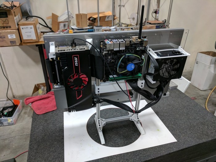
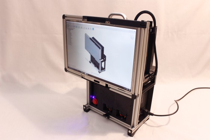
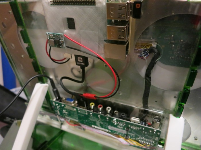
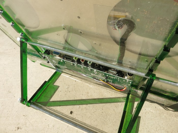
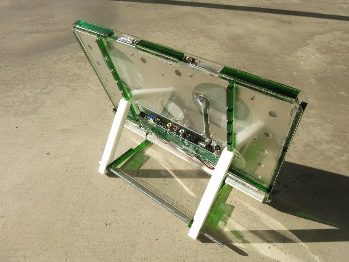
The Luggable PC Mark II project is built around the Lenovo L24q-20 QHD (2560×1440) monitor. One of the reasons I chose this screen was because its AC power adapter is relatively small and I thought I could package it within the enclosure. For Revision A, I didn’t do anything fancy: the power adapter is zip-tied to one of the aluminum extrusions. I should do better for Revision B.

Monitor PSU zip tie

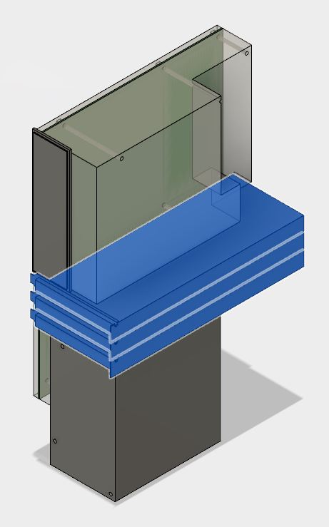
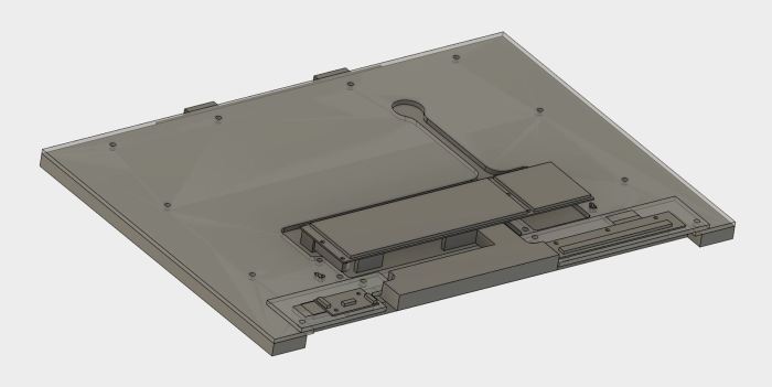
The goal is to design a mounting bracket that can hold the AC adapter in place, look relatively elegant, allow easy removal of the adapter, and do it all while taking up minimal space. This is commonly solved by a bracket with flexible claws to hold the object in place, so I designed one of my own tailored to the dimensions of this adapter.

Monitor PSU CAD

My 3D printer can translate this CAD object into the real world, but it needs a little help. Deposition modeling type 3D printers like mine can’t put things in arbitrary locations in space, due to pesky things like gravity. The fastener screw hole in the middle has enough surrounding material for the 3D printer to build up the top of the hole despite gravity, but the tines at the end need to be supported while printing.

This is one of the strengths of Simplify3D as slicer – the ability to customize these printing supports. I wanted supports to help me print the fork tines on the ends, but I didn’t want any support for the fastener hole as they are unnecessary and, if present, would be very difficult to remove. In Cura 2.x (which came with the 3D printer) supports are an all-or-nothing proposition. I could not selectively choose what to support. Simplify3D allows me to do so.

Monitor PSU S3D

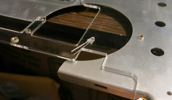
And thanks to this custom support, I have a clean fastener hole along with fork tines to hold the power adapter in place. I don’t use Simplify3D custom supports very frequently, but when I do, I’m very glad I have the tool at my disposal.

The Tale of the Scale

With the core components and the auxiliary accessories installed, I have a usable computer. It is time to find out how much this setup weighs.

Weighing this configuration establishes a lower bound for the final contraption. Whatever a complete luggable enclosure may weigh, it must have all the parts present on this first draft, so it’d be impossible to be any lighter.

Luggable PC Mark I weighs in at 17.5 pounds and while it is no lightweight, I’ve had no problems lifting it by the handle and carrying it around. Some of the credit goes to the strong and smooth handle sold by Misumi for the HFS-5 extrusion. (HHDFL19) The strength gives confidence for carrying and the smooth surface helps make it comfortable.

Tux Lab’s “Luggable Frame” project with the Yamakasi Catleap 28″ monitor and the HP Z220 small form factor case sets the upper bound for weight. While it can be carried short distances (say, across the room) at over 30 pounds it is not practical to carry much farther. I expect Mark II to be lighter than that combination, but would it be lighter by a useful amount?

I didn’t need precise measurements – it’s just for a rough baseline – so I used the most convenient weight measuring device: my bathroom scale. I mentally gave myself a drum roll as the bathroom scale took measure of the Luggable PC Mark II…

Bathroom scale

And the number that came up was… 16 pounds!

That’s not a bad starting point. I expect the final enclosure to weigh more than 1.5 pounds, so the first usable luggable Mark II will weight more than Mark I. That’s not a huge surprise since the larger screen is significantly heavier than a salvaged laptop panel. The challenge would be to keep the weight as low as it is feasible.

Given a bare-bones skeleton baseline of 16 pounds, I’ve set for myself a target weight for the final product at 20 pounds.

Onward to the next iteration.

Need Low-Voltage, Low Power Wire Bundle? Use Cat 5e Data Cable!

In addition to USB ports, most PC tower cases also come with a front control panel that connects to the motherboard. This is where the power button, the power LED, and the hard drive activity LED are shown to the user. There is sometimes also a reset button, but they appear to be getting phased out. Personally I haven’t needed a reset button in years and any presses of the reset button in that time has been accidental (and usually instantly regretted.)

Part of building my own PC case is supplying these controls myself. This was part of the fun of building Luggable PC Mark I. For the power button, I wired up a big red button of the type typically used for arcade consoles.

The headers are easy to find (*), as are the LEDs and their associated current-limiting resistors. The momentary-on push button is also easily found. What gave me headache were the wires for them all. None of them need to carry a high voltage, or a lot of current, but there is a bunch of them and it was a hassle to keep them the same length and not tangled up. Given the hassle and the lack of need, it is obvious why I didn’t put a reset button on Mark I. Without reset, I only had to deal with 6 wires instead of 8.

Thanks to Tux-lab, I’ve learned a much better idea I can apply to Mark II: use a segment of standard networking cable. In my case, I have a spool of Cat 5e I can cut arbitrary lengths from. Cat 5e has 8 wires, enough for the purpose. Even a reset button if I wanted, which I don’t, so the fourth pair of wires were removed.

This is a neat trick, I’ll have to keep it in mind whenever I need low-power, low-voltage wiring bundles in the future.


(*) Disclosure: As an Amazon Associate I earn from qualifying purchases.

FYI: Lenovo L24q-20 sale $169.99 @ Best Buy

If anybody wants to follow along and build their own Luggable PC Mark II, as of this writing Best Buy has the Lenovo L24q-20 monitor on sale again for $169.99, a $30 discount (~15%) off the regular $199.99 price. I think this is part of the weekly deals so the price should be good through Saturday 8/26, 2017.

UPDATE: Price is back up to $199 as of 8/27, 2017. But since it’s been discounted to $169.99 twice already within the past few months, I’m sure the sale will roll around again.

BestBuyL24q-20Sale

Extra USB Ports Via Motherboard Headers

My Gigabyte Z270N-WiFi motherboard packs a lot of features into a little Mini-ITX form factor. One downside of packing features into the standard motherboard back plate is that they crowd out the USB ports and I’m left with only 4.

Well, 4 of the popular rectangular types anyway. I get a fifth USB port of the new USB-C connector that I like, but don’t have many uses for yet.

The surface of the motherboard was also cramped, and instead of the usual two (or more) USB2 headers, this board had only one USB2 and one USB3 header. Which should be enough.

Typically, a modern PC tower case has a few USB ports exposed to the user, and those ports connect to these headers. Since I’m building my own case, I’ll have to come up with something on my own.

I could buy the pieces and solder up my own, but it’s hardly worth the effort when Amazon marketplace has many vendors selling them ready-made. Since USB2 is not a very demanding specification by today’s standards, I decided I might as well try the lowest bidder first. At the time of my window shopping, that meant this particular two-pack. (*)

These plugs came mounted on metal plates suitable for installation into a standard PC case. The mounting was not a perfect fit: the plug bulged as if the distance between holes on the plate is half a millimeter narrower than the actual distance between screws on the USB plug. But that’s OK in my book, since I’m not using the metal plate anyway. For the Luggable PC Mark II I removed the plugs and zip-tied them to one of the supports. I’ll design a better home for them on the next draft.

The other problem was its wiring sheath not fitting well inside the molded plug. Showing inside wire at the junction. Since I don’t expect much movement and flex in this wire, the lack of strain relief should not be a functional issue.

Bad Strain Relief

The important part is that they function just fine as USB ports.


(*) Disclosure: As an Amazon Associate I earn from qualifying purchases.

Aftermarket Antenna for Gigabyte Z270N-WiFi

One of the reasons I chose to buy my Gigabyte Z270N-WiFi motherboard is right in its name – it has built-in WiFi. Inside the box is a small antenna with two wires. The antenna is on a hinge so it can be tilted at an angle or folded down against the base, which has a magnet on the bottom.

Gigabyte Antenna

I thought this system was well designed for the typical desktop PC. The motherboard ports are usually sitting close to the ground against the wall and not a good place to have antenna stick out. Also, tower cases are typically steel, friendly for magnet attachment. So the bundled antenna and its wires allow the antenna to sit on top of the tower case where it should get a better signal.

My PC, however, is not a typical PC. Steel sheet metal is currently beyond my capabilities, so my case materials will be aluminum extrusion, laser-cut acrylic, and 3D-printed plastic. None of which are magnetic! Also, the placement of the motherboard meant the ports plate is top and center of the case, which is actually an idea location for an antenna.

Thanks to help from Tux-Lab, I learned the WiFi connector on my motherboard plate is of type RP-SMA. Given this information, it was trivial to find all the connectors for sale by Amazon vendors world-wide. I quickly noticed some of them only claimed to support the 2.4GHz band. A quick check on the spec sheet confirmed my motherboard WiFi is a dual-band unit so I need to look for dual-band antenna.

I eventually decided to try this item (*), a simple dual-band design with relatively high gain of 7 dB. After its arrival, I took a few measurements with the iwconfig tool.

  • No antenna: Link Quality=32/70
  • Original bundled antenna: Link Quality = 60/70
  • New aftermarket antenna: Link Quality = 70/70

Fewer wires, simpler design, higher link quality, I think this is a win!

And on a completely silly note, I’m amused by the fact they made my Luggable PC Mark II look like an old-fashioned TV with rabbit-ear antenna.


(*) Disclosure: As an Amazon Associate I earn from qualifying purchases.

Bare Skeleton for Component Fit Test

After all the research and purchasing the parts, it’s time to put them all together to make sure they fit and work together. This first draft is only a test of component fit using a minimalist bare skeleton. It would not yet be a PC that I can lug around.

In addition to the aforementioned GPU mount, I had to design and 3D print a few other parts. The SFX12V PSU needed its own mounting bracket. As did the screen: I had the metal plate mating surface liberated from the monitor stand, but I needed to design and 3D print a part the metal bracket will attach to and in turn attach to the rest of the skeleton.

The skeleton itself is built out of Misumi HFS3 aluminum extrusions, which is 15mm by 15mm in cross section and well-suited to work with M3 screws and nuts. The nuts are the best feature of HFS3 – all I needed were standard M3 nuts. In contrast, HFS5 needed special Misumi M5 nuts that cost way more than standard M3 nuts.

The design of the skeleton is nothing special – a simple functional design that resembles the Yamakasi Catleap + HP Z220 luggable frame built several weeks ago at Tux-Lab.

I needed a laser-cut sheet of acrylic to tie everything together, so I packed up all the bits and pieces in their original enclosures for the trip to Tux-Lab.

Luggable PC Mark II parts

One laser-cut sheet of acrylic and a few hours of assembly work later, I have the first draft for Luggable PC Mark II! The components are left open and vulnerable but that’s not the point of this first draft. It’s just to make sure all the parts fit. Some minor fit issues were encountered but nothing terribly major.

I declare the fitness test a success. Onward to further refinements!

Luggable PC Mark II first draft

Researching PCI Express Extension Cables

Building Luggable PC (Mark I) determined that a direct GPU connection to the motherboard takes up a lot of space. For Mark II, a simple riser card would not fit. That leaves us with using a PCI Express extension cable.

A flexible cable allows significantly more freedom in placement. Given this freedom, I wanted the GPU cooling intake to face the same direction as the CPU fan cooling intake. This is better than a simple riser card, which would result in the two fan intakes facing opposite directions. To flip the GPU (and its intake) around, I’ll need a longer cable to take the circuitous S-turn.

One word of caution: most extension cables are sold to crypto-currency miners (*), who want the flexibility to pack as many GPUs into one computer as possible. Miners are not concerned with bandwidth and latency over the PCIe bus, but I am!

Hunting in the sea of products aimed at miners, my next task is to determine how much I need to pay for a decent quality cable. Amazon vendors sell cables for anywhere from $7 to $70. Some of the reviews left on the $7 cable (*) warned of destroyed components, making me jittery about going cheap. This cable has the potential to destroy a multi-hundred dollar GPU, a multi-hundred dollar CPU+Motherboard, or possibly both! I climbed up the Amazon price ladder until I found a $30 unit by “EZDIY” (*) with a significant number of reviews, none of which complained about destroyed components.

Then it came time to mount everything. The freedom of placement given by the extension cable also takes away the structural connection to the motherboard. I will need to design my own GPU mounting bracket with zero structural help from the motherboard mount.

The PC interface slot standard, built up over decades tracing back to the old ISA expansion cards, is quite a challenge to deal with. Optimized for mass-production with sheet metal, it is not very friendly to hobbyist 3D printing. But it’s a problem solvable with enough creativity in Fusion 360 and multiple test prints on the 3D printer.

Once it was all set up, I tested the configuration of both the extension cable and the 3D-printed custom GPU mount to verify everything works. It was a little jarring to see my GPU sitting on top of the box instead of its usual home inside.


(*) Disclosure: As an Amazon Associate I earn from qualifying purchases.

Researching PCI Express Riser Cards

When I take my Luggable PC (Mark I) around, I sometimes attract attention from like-minded PC builders who look over what I’ve done and offer helpful suggestions. I’m incorporating the Greatest Hits into construction of Mark II. We’ve covered two of them already: (1) Use a Mini-ITX motherboard and (2) use a smaller power supply. Now let’s cover (3) Use a PCI Express riser or extension.

The motivation comes from the fact standard PCI-Express GPU placement is very inconvenient for compact packaging. The motherboard and the GPU are placed at right angles to each other taking up tremendous amount of space. In Mark I I packaged components around the GPU the best I can, but it was far from ideal.

We need more freedom to rearrange these components and that can only come from putting in an intermediary between the PCI Express slot on the motherboard and the GPU connector tab, something that changes the nature of the connection.

First option is a PCI riser card like this unit (*) on Amazon. It gives us a 90-degree turn which is commonly used in servers to fit cards within a rack-mounted enclosure. Rack-mounted servers don’t usually need powerful GPUs, so these customers don’t run into the problem we have: Full power GPUs are two slots wide, the turn means it can only be used at the very edge of the motherboard or else the card will collide with the motherboard. For Mini-ITX boards, this presents an additional challenge because the GPU’s metal bracket, when turned 90 degrees and inserted to the one and only slot on a Mini-ITX board, will also run into the motherboard ports back plate.

Since a simple riser card wouldn’t work for this project, let’s look at extension cables next.


(*) Disclosure: As an Amazon Associate I earn from qualifying purchases.

Researching Small PC Power Supplies

A major goal of Luggable PC (Mark I) was to use components I already had on hand, which meant a full-sized ATX power supply unit (PSU) because I’ve never bought anything else before. For Mark II, I’m opening up the project budget to buy a compact power supply for the system.

There are plenty of small proprietary PC power supplies available in the aftermarket but low-production items will have limited selection and may be difficult to replace. The only units that were remotely interesting were the PSU for high-volume small form factor PCs of large manufacturers like HP or Dell. But they tend to be low powered units rated at 250W or less and also lack the power plugs needed to feed a power-hungry full size GPU.

So I started looking at the standardized PSUs. In the ATX power supply specification I found online (revision 1.31 dated April 2013) I learned there was a significant step in the evolution of ATX power supplies that shifted original focus from the 3.3V and 5V rails over to the 12V rails. This explains the “12V” suffix on some of these specifications – when a manufacturer names their ATX PSU as a “ATX12V” power supply, they declare 12V focus on power capability.

However, the first three letters still describe the physical form factor. I didn’t find many CFX12V or LFX12V units available. TFX12V and FlexATX12V are more common but they are equivalent to those HP/Dell PSUs with low wattage rating and no PCI-Express card power plugs. We want something smaller than ATX12V, so that leaves SFX12V.

Thankfully there seems to be a healthy SFX12V niche in the ecosystem. They do tend to be lower in power rating than full sized ATX12V but I expect 450-600W to be plenty. And they have most of the power plugs of a full ATX12V unit, including those valuable PCI-Express power plugs.

The power plugs actually present a bit of a problem: any wires I don’t use in my system is dead weight and taking up space. In theory this can be resolved with a SFX12V PSU with modular plugs and wires. I ended up getting one modular (Corsair SF450) and one non-modular (FSP Group FSP450) SFX12V PSU to experiment with.

On the physical form factor specification, SFX12V was only a few centimeters smaller in each dimension relative to ATX12V. But those numbers understate the reduction in physical volume. When I pulled them out the box I was quite pleased at how compact they were. This is going to be a tremendous help in keeping Mark II slim.

IMG_5201
ATX12V and SFX12V power supply units side by side illustrating difference in volume.

Lenovo L24q-20 Monitor: Core of Luggable PC Mark II

Once I decided the Luggable PC Mark II project will be built around a retail available 24″ monitor with QHD (2560×1440) resolution, it narrowed down the list of screens I need to keep an eye open for deals. A few weeks after the decision, a promising candidate popped up: Best Buy put the Lenovo L24q-20 on sale for $170, a 15% discount from its usual $200 price.

The specifications look promising. The panel type is IPS, which is great as I had expected to find only the TN panels in the lower price range. The physical dimensions are impressively minimal, with a very thin bezel on the top and sides. More than half of the back side is flat, making it easy to pack computer components in that space. The shipping weight is light, implying either the screen is lightweight (good) or that they really skimped on packaging (not as good).

The monitor had few inputs (one HDMI port and one DisplayPort) but I only need one so that’s fine. I was less thrilled with the fact all the plugs (video and power) stick straight out the back instead of pointing downwards. The latter would have made it easier to package everything in a slim enclosure.

The other disappointment is the lack of standard VESA mount points. Their presence would make chassis integration straightforward, but it is not itself a deal-breaker. It depends on whether I can work with the nonstandard mount.

Having done all the research I could over the web, I went into the local Best Buy for a look at the display unit to learn things they don’t put on the spec sheet.

Item #1: Power. I could tell the monitor uses an external power converter, but the specifics were not listed. Ideally the monitor can run on 12V DC because then I could rewire it to draw that 12V from the computer power supply. Sadly this Lenovo takes 19V. On the upside, its DC power converter is very small so I think I can package it in my enclosure.

Item #2: Mount. The final make-or-break factor… how the monitor is mounted to its stand. Again, not something listed on the spec sheet. I turned the Best Buy display unit around, found the release latch, and separated the monitor from the stand. I saw the mating surface of the stand is a metal bracket fastened by 7 Philips screws. I can remove those 7 screws and use the metal bracket in my own chassis as attachment point for the monitor.

Yes, I can work with this! I put the display unit back together and grabbed a box to take home. I bought what turned out to be the last new unit in stock.

IMG_5200
Lenovo L24q-20 monitor stand with the metal mounting bracket removed to show the 7 fastener locations. 4 machine screws into metal, 2 on the left and 2 on the right. In between them, 3 self-tapping screws into plastic. The bottom two round objects are not screw locations – they are posts to help locate the mounting bracket.

New Project: Luggable PC Mark II

I’ve been using my Luggable PC for about four months. It was originally built with retired computer parts, but the concept worked so well I transplanted the guts of my main desktop tower into the enclosure and now it is my only computer. I use it at home connected to my Monoprice 28″ UHD monitor (predecessor to the current Monoprice 28″ UHD monitor) and when I want a computer on the go, I close the screen and take it with me.

1454021491161140759
Luggable PC Mark I

Unfortunately that means leaving the UHD (3840×2160) monitor behind. While the built-in 17″ screen (with the flip swivel hinge I’m proud of) is a respectable 1920×1200 resolution, it feels quite cramped when I’m spoiled by a UHD screen at home.

So that became the motivation for a sequel: the Luggable PC Mark II. The main thrust of the project is a larger, higher resolution screen. And this time, I want to build the chassis around a monitor available at retail, instead of a salvaged laptop panel like the Mark I. Being specific to a salvaged panel is not very friendly for others to build their own. Tailoring Mark II to a monitor people can buy would be better.

So the next question is size. Tux-Lab experiments with the Yamakasi Catleap monitor taught me 28″ is too big to be easily portable. Looking over the computer monitor market for sizes between 17″ and 28″, the 24″ size seems to be the best one to experiment with. It is a popular size with a wide selection of makes and resolutions up to and including UHD if the budget allows for it.

And while external dimensions vary, they are mostly less than 14″ high and 22″ wide. Why these dimensions? They are the limits for carry-on luggage at United Airlines, which seems roughly representative of (or possibly more restrictive than) most airlines. I still hold the dream a Luggable PC can fit in an overhead compartment. (Assuming I can get it past TSA.)

There’s no point in a 24″ FHD (1920×1080) monitor since that’s no better than the screen I already have.  My project budget is not daring enough to jump straight into a 24″ UHD monitor price tag. So the hunt is on for a 24″ QHD (2560×1440) monitor that I should be able to find for well less than half the price.

SGVLUG: Custom Computer Projects

Last night I had the opportunity to present my Luggable PC, FreeNAS Box, and Portable External Monitor projects to the San Gabriel Valley Linux User’s Group. Though the projects themselves have only minimal relation to Linux, the spirit of customization and project sharing fits well with the Linux open source ethos.

SGVTalkTitle

I hauled in all the latest versions of my projects. Plus all the earlier drafts and revisions that have yet to be disassembled and pitched. More visual aids is always better than less and they proved quite popular after the talk concluded and people came up to look over the projects up close.

Some of the audience found the topic engaging and stayed after the talk discussing aspects that didn’t make it into the talk and offered ideas for future exploration. Some of those ideas were already on my to-do list and some are novel ideas I should explore.

A few people left early, whether they had other obligations or they got bored I might never know.

I don’t have a lot of public speaking experience so this was a great opportunity for me to get some practice in a low-pressure environment in front of a like-minded crowd. At the moment I’m not planning to go work in a mega corporation again. I might not need good presentation skills in a small business, but if I want to get entrepreneurial and start my own business, I will definitely need presentation skills.

This was good practice, building up the public speaking skill one bit at a time.

Much like my design and fabrication skills.


One Month of Google Pixel

When my Nexus 5X was rendered unusable by my negligence at the swimming pool, I needed to order a replacement phone. Since I want to stay on the Google Fi service, my device options were limited. Fortunately, I had been interested in the Google Pixel as soon as it was released and thought I’d wait for its price to drop or until I couldn’t wait any longer. With the death of the Nexus 5X, the latter scenario has come to pass. (And as of this writing, the Pixel prices just dropped as well.)

Some remarks from my first month living with a Google Pixel:

Camera: One of the much-touted features upon the launch of the Pixel was its camera. And it is indeed quite excellent! A huge step forward relative to every cell phone I’ve owned… except for its immediate predecessor. In my usage, the Pixel camera was only a minor improvement from the already-excellent camera of the Nexus 5X.

Exterior: Another touted feature is the aluminum body that tries very hard not to be a direct copy of an iPhone. This does not suit my personal taste: I prefer my phone bodies to be plastic which has more give than metal. Every phone I’ve owned to date are plastic-bodied and their corners all show the times when they’ve been dropped, bounced back, and only left with a tiny mark. Aluminum does not flex like that. If I should drop this phone, the aluminum will bend and stay bent instead of bouncing back. So this aluminum body phone became my first phone with a protective case (*). What’s the point of fancy aluminum if I have to wrap it in plastic anyway?

Pixel Launcher: The Pixel OS is mostly stock Android with a few changes. The Pixel Launcher is the most visible since that’s what the user sees all the time. I appreciate most of the changes but I didn’t care for the weather taking up the top row of the home screen and displacing 5 icon positions. Knowing the weather is nice, but it’s not worth giving up an entire row of 5 icons I could have placed there.

Performance: On paper the Pixel should vastly outperform the 5X. In my daily usage the difference is noticeable but not earth-shattering. Another incremental improvement.

Daydream VR: The performance advances are more significant when running Google’s new mobile VR effort, Daydream. It is much superior to Google Cardboard from the first moment I put on the headset and grabbed the remote. But it also comes at significantly higher cost. Is the cost worth it? Not at the moment – the Daydream app ecosystem is still thin, but I’m optimistically looking forward to more.

Storage: I had the 16GB edition of Nexus 5X, and over its lifetime it received two major Android releases, each larger than the last. Towards the end it was quite a struggle to stay within 16GB. The smallest Google Pixel starts at 32GB, in my view a tacit admission of Android’s weight gain.

Summary: If I knew a month ago what I know now, I would have ordered a refurbished 32GB Nexus 5X instead of a new Google Pixel.


(*) Disclosure: As an Amazon Associate I earn from qualifying purchases.

Portable External Monitor v3 + Raspberry Pi

The work for portable external monitor (version 3) is winding down and now it’s time for it to get to work. First up: help configure a Raspberry Pi to run the ARM port for ROS Kinetic.

PEMv3vitPi

This is the culmination of several different projects documented on this blog. Most obvious is the portable external monitor project. Which incorporated LED light design from the edge light investigation project. The 12 volt power from the LCD panel driver board is tapped to power the Raspberry Pi, stepped down to 5 volts by the MP1584 voltage step-down converter recently purchased on Amazon. The Raspberry Pi is housed in the 3D-printed enclosure that was one of my first projects in Onshape.

And on the software side, I’m just getting started on learning the Robot Operating System. This specific configuration will help me learn how to set up and run a ROS network across multiple nodes, one being my desktop PC and the other this Raspberry Pi.

Many projects, combined to become whole new projects!

Portable External Monitor v3 LEDs

Before we wrap up version 3 of the Portable External Monitor project, we’ll add a purely aesthetic finishing flair: some gratuitous LEDs! This is the first opportunity to apply what I’ve learned from the LED edge lighting experiments conducted a few weeks ago.

When I first received and examined the LCD panel driver board (*) from the Amazon vendor, I noticed that a few connectors were unused. One of them caught my attention: it appears to be a way to share the 12 volt power source without the need to perform any soldering work on the circuit board.

12VPower

A little Google search determined the connectors on the other side of the circuit board to be 4-pin JST PH-type connectors. So back to Amazon I go to obtain the connectors (*) for this LED project.

The slots for the LEDs were cut into the spine for the PEMv3 core. It was easy to place the LEDs in those slots and wired them up to the JST PH connector in series with appropriate current limiting resistors.

LEDCutout

When turned on and running, PEMv3 was already pretty brightly lit: the fluorescent back light for the panel emits light in many other directions. It is visible from multiple locations on the side, and also visible across most of the back side. Adding these LEDs (green, to match the 6mm acrylic used in the enclosure) is fairly redundant but succeeded in making everything even brighter.

Maybe I’ll find the brightness annoying in due time. But for now, version 3 of the Portable External Monitor shines bright. May it shine for a long and happy time.

Or until I decide to build version 4. Whichever comes first.


(*) Disclosure: As an Amazon Associate I earn from qualifying purchases.

Portable External Monitor v3 Enclosure

Once we have a compact core built for the portable external monitor project, it becomes relatively easy to design and build an enclosure around it. Mostly an acrylic box that functions as a sleeve into which the core can fit, but also some additional components so we can have an integrated stand.

Once the individual parts are cemented together, a quick test to verify the parts fit.

PEMv3EncTestClosed

PEMv3EncTestOpen

Then we install the core.

PEMv3AssembledClosed.JPG

PEMv3AssembledOpen

Two problems were immediately apparent.

First problem: movement along the threaded rods were not constrained. In the ideal CAD world, the parts only hinged about a single axis. In the real world, they slide all over the place because I forgot to design in anything to prevent that movement.

PEMv3Chaos

Second problem: The threaded rod at the top did not function as designed. Not only did it fail to clip in to the top and hold things closed as I had hoped, it also blocked access to the ports in the open position.

PEMv3PortsBlocked

To constrain movement along the threaded rods, I added a few 3D-printed parts to the base. I also replaced the upper rods of the stand with 3D printed parts for better alignment with the adjacent rail and eliminate the need for the threaded rod that ended up blocking the port. It still doesn’t clip to the rail and hold everything closed like I hoped, but it is a big step forward in functionality.

PEMv3DP

Once that is all done, the portable external monitor became far more portable. While maximum thickness stayed about the same, most of version 3 was thinner with only the main circuit board area reaching that maximum thickness. In contrast, all of version 2 were of the same maximum thickness. We shrunk along the remaining physical dimensions: the height shrunk by 1cm, and the width shrunk by a dramatic 6cm.

PEMv2v3

All of the above combined to allow PEMv3 to fit in my JanSport backpack. And carrying it will be far less of a chore now due to its significantly lighter weight. The fully equipped PEMv3 enclosure is now roughly half the weight at 4 lb. It is in fact lighter than even just the acrylic portions of PEMv2, which weighs in at 5 lb empty of electronics.

All those advances, and we have an integrate stand as well! Version 3 should be a far more usable unit than version 2 was.

Portable External Monitor v3 Screen and Components Core

Now that the unused bracket has been cut out of the way, it’s time to pack components into that newly freed space. Due to the CFL backlight power wire, there’s not a lot of room for creativity to place the CFL voltage converter board. It ends up approximately at the same place as the old dead CFL driver board where the bracket used to be. That left enough room on either side of the driver board: the buttons circuit board on the left, and the IR receiver on the right.

One unfortunate aspect of these aftermarket circuit boards is that they’re designed towards ease of construction, allowing easy mixing-and-matching components. Large components, especially the cable connectors, make it easy to snap things together. But the large connectors work against us when we’re trying to pack everything tightly. There’s a good reason they don’t use these types of parts when building thin and light laptops!

This hampers our effort packaging the buttons board and the IR receiver board. Everything is on one side of the circuit board for ease of construction, working against a compact layout. For example, we want the user-facing bits (buttons and IR receiver) on one side of the circuit board, and the cables on the back side for connection, but that’s not how they were built.

Building something out of laser-cut pieces means the Z axis is constrained by the thickness of the acrylic stock available. That plus the inconveniently placed cables and connectors made the whole exercise a challenging game of 3D jigsaw puzzle. Here’s my solution for Portable External Monitor, version 3:

PEMv3Core

While the components aren’t all on a single sheet of acrylic, we got close enough that it’s actually a pretty tightly integrated unit. Now this core unit, consisting of the screen plus supporting circuit boards, needs an enclosure around them.

PEMv3Core

Portable External Monitor v3: Trim Unused Bracket

For the portable external monitor project, version 3 (PEMv3) , we want to pack our components more tightly together to create a compact package. The most inconvenient barrier to the goal is the old back light driver board mounting bracket. While the circuit board itself was already dead when I got the laptop and promptly removed, the bracket for the driver board was still present during PEMv1 and PEMv2. The aftermarket back light driver board is significantly larger than the original Dell part and would not fit in the bracket. I had originally hoped the bracket can be recruited into a new role but none had ever come up.

So now it is time to trim off the bracket.

The front part of the bracket is riveted to the thin metal bezel of the LCD panel. The rivet makes it easy to remove with a Dremel grinding tool, but I was concerned about the potential for metal particles to damage the panel. I spent more time covering and wrapping the rest of the panel than I did removing the rivets.

LCD bezel rivet

The rear part of the bracket is part of the panel mounting frame. Since there were no electronics here, I didn’t have to worry as much about damage. I will need to thoroughly clean up the work piece afterwards to minimize the number of particles that are still sticking, but I didn’t have as much risk while doing the actual cutting.

Frame Before

I chose to minimize the cut length which removed more metal than necessary because the shortest cut connected the two large bottom holes. We should still have enough structural strength and mounting holes for the frame to be useful.

Frame After

With the old bracket out of the way, it’s time to pack our components into the space previously occupied by the bracket.


Portable External Monitor v2 Problems To Fix in v3

And now, back to the portable external monitor (PEM) project. Version 2 has been in use for several weeks, called into duty when I needed a screen. It was used to help me install and smoke test ROS on a Raspberry Pi 3. It was also used for the FreeNAS box, which was ideal because FreeNAS only needs a screen briefly for setup.

Functionally speaking the portable external monitor has been working well. But the physical form factor left room for improvement: it wasn’t as portable as I would like.

The first part of the problem is weight: PEMv2 was built by stacking sheets of acrylic that had holes cut out to make room for components. There’s no fundamental reason why this subtractive construction technique had to be heavy. But in practice, holes were cut only when needed to make room. The result is a lot of excess acrylic. Acrylic is not super heavy, but it all adds up to just over 8 pounds which is ridiculously overweight for a 15″ screen.

The second part of the problem is size: PEMv2 was intended to fit within the width and height of my JanSport backpack. When assembled, I had a facepalm moment: it does not actually fit into the backpack because PEMv2 is rectangular and the backpack is not. The top of the backpack is rounded, with no room for PEMv2 top corners.

BackpackPEMv2

Lastly: while PEMv2 was thick enough to stand upright on its edge, it is easily tipped over and the upright vertical screen angle is not very ergonomic. We can definitely do better.

PEMv3 will try to address all of the above issues. To minimize physical volume, we’ll need a more compact way to package all the components. We’ll need to build our enclosure using less acrylic to further reduce weight. And we’d like to have an integrated stand that can securely prop up the screen at a better viewing angle