AI Generated Rovers Not Mechanically Sound (Yet)

Taking a break from exploring electronics, I went to the to-do list and picked off the item “look into generative AI”. This particular story started several years ago when GitHub user @johndpope opened a GitHub issue on my Sawppy repository advocating for a Lexan body shell. Aesthetics is not my focus for Sawppy but I’m glad to see others are thinking about cosmetic enhancements. In a recent update, @johndpope added a large number of images generated by Stable Diffusion. They’re really… something. If there’s potential here, I really have to squint to see them. For the most part these images generated by Stable Diffusion were not mechanically sound. Or even mechanically feasible. Or even sane. It’s a patchwork of bits I recognize, assembled into a surrealistic dream that reminds me of Salvador Dali paintings.

(Image credit: Stable Diffusion from @johndpope prompt)

What’s going on here? An Ars Technica article about Stable Diffusion running on Apple Silicon had put a note in the back of my mind, and after seeing @johndpope updates I thought I would look into it further. I do own an Apple MacBook Air with a M1 Apple Silicon processor appropriate for the links in that Ars Technica article, but it is my understanding my gaming PC’s NVIDIA RTX 2070 GPU would be faster still. So I followed instructions on this @AUTOMATIC1111 GitHub repository to run Stable Diffusion locally on my machine.

My experiment results were no better than what @johndpope had posted. Jumbles of things, nothing very coherent, and the occasional misshapen nightmare fuel. Other tools like Midjourney and OpenAI’s DALL-E were supposed to be better, but they were commercial offerings not available for running locally and I didn’t feel like this experiment was worth handing over my credit card. Then I read Microsoft had licensed DALL-E for Bing Image Creator. No credit card necessary, just a Microsoft account. Well, I have that!

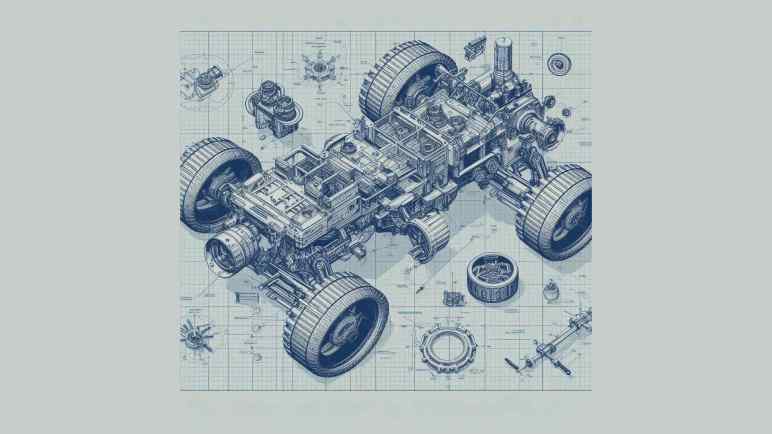
To see if things have gotten better, I headed over and here’s the most sane result from the prompt: “mechanical diagram of a six-wheel mars rover in blueprint style

(Image credit: Bing Image Creator from my prompt)

This is better looking than what I got out of local Stable Diffusion. (And ironically less Dali-like, given the DALL-E name.) But it is clearly weak on sound mechanical design concepts starting with the fact I asked for six wheels and got only four. Symmetry is not a well understood concept, either, as these four wheels are visibly misaligned relative to each other along orthographic axes. And there are random parts scattered around, what’s up with that? And finally, it seemed to have ignored the “Mars” part of my prompt as this creation shows no indication of adaptations for a Martian operating environment.

I tried a few variations on my prompt and my impression of this tool is to lean into its tendency for mechanical nonsense and get designs packed with greeble, because it’s certainly got plenty of visual noise. But I certainly can’t use it for anything that can function mechanically. To be fair, mechanical design is not the focus of such image generators. Plus, this field is still evolving rapidly so in a few months things might be very different. But at least for today, image generation AI pose no threat to mechanical engineering jobs.

A short while later I got another idea: instead of trying to make it do something mechanical, how about an abstract cartoon rover mascot?


[UPDATE]: In the comments, Quinn Morley got an interesting looking rover from the prompt “SAWPPY the rover, with six wheels and a body made of glass instead of metal, on Mars.

(Image credit: Bing Image Creator from Quinn Morley’s prompt)

At first glance, this looks really good!

But upon closer inspection, I noticed the suspension linkages are attached to tires instead of hubs, and there seem to be only five wheels instead of the six specified. Something about this particular combination of flaws is appealing to DALL-E’s inscrutable brain because it also showed up in my cartoon mascot experiment.

Laptop Backlight External Power and Optional Polarizer

I have a salvaged LED backlight module that I intend to turn into my workbench light. The LCD pixel array itself is gone, I’m working with the backlight LED strip, associated light diffuser, the polarization film, and metal frame. I have the display circuit board as well, but I’ve chosen against interfacing with its onboard backlight LED controller and voltage boost converter in favor of the simpler solution of providing external power for the LEDs. My LED tester says I need to find about 32.2V DC to drive these LEDs at 20mA.

I rummaged through my bin of salvaged power supplies. I found this HP inkjet printer power supply CM751-60190 who previously helped with vacuum fluorescent display adventures. I measured its open-circuit output voltage at 31.8V DC. Perfect! This eliminates the need for a boost/buck voltage converter, and would drive the LEDs at a little under 20mA. Giving me a bit of safety margin because I’m not monitoring current draw as the real backlight controller does, and hopefully driving these LEDs at slightly under 20mA would extend their service life as well.

All six strings are wired in parallel to this power source, and it lights up quite nicely. Despite being a smaller panel drawing a tiny fraction of the power, it illuminates my workbench almost as brightly as the large Monoprice monitor thanks to the fact it isn’t working through multiple layers of LCD infrastructure: this was just the backlight.

I considered the effect of applying power directly to these pads. What would that do to the rest of the circuit board? The 31.8V DC would be applied to the output of the onboard boost converter circuit. It would definitely power up the output buffer capacitor of the boost converter, which is fine and possibly even helpful. Beyond that capacitor would be a diode blocking the 31.8V from going any further, leaving the rest of this circuit board alone. This setup suits my purpose just fine so no further modifications are required.

After the power situation was settled, I want the polarization layer available for optional use. To each corner I taped small magnets extracted from an iPad case. I did the same for each corner of the polarization filter acrylic. Once done, I can attach the filter magnetically when I want to take photos with polarized light. The rest of the time, I could remove that filter for brighter illumination. I also taped four magnets under the table so I have someplace to store the polarization filter when I don’t need it.

Later I realized this used 12 magnets when I only really needed 4 on the filter. The backlight corner and storage locations could have been plain steel for those 4 filter magnets to stick to. But I already had plenty of little magnets available, and using them saved me the effort of trying to find and cut small steel pieces. If I ever run short on small magnets I can come back. In the meantime I’ll leave it as-is.

So far this workbench lighting solution is better than using the big Monoprice monitor. No obvious problems surfaced within the first hour of use, so I’ll keep using it until I find a reason to tinker with it again. I’ve got more electronics learning to do!

Laptop Backlight for Workbench Lighting

I quickly discovered several reasons why a computer monitor makes for a poor lamp within an hour of bolting one to the bottom of an IKEA LACK coffee table serving as horizontal mounting stand. The original motivation was to have a for a polarized light source and it worked well enough to give me a few neat pictures. But its inefficiency meant it was relative dim for the power consumed, turning that power into a lot of heat, and it made non-backlit LCD screens (with their own polarization filters) unreadable at certain angles.

I still want polarized light capability for my workbench light, but it should be an optional component for only when it is useful. Similar to the corresponding camera lens polarization filter which I can remove as needed. I also want the light to be more efficient so it doesn’t waste as much power as heat. Leading to my next attempt, pulling from my stack of salvaged laptop screen backlights. They are very energy efficient as they were designed for battery-powered devices. I had successfully transferred a few of their corresponding polarization filters to a sheet of clear acrylic. And I kept the laptop lid backing to serve as mechanical mounting frames. This is what I will convert to an energy efficient polarization-optional workbench light.

There’s a LED controller with associated voltage boost converter on this circuit board, but this time I’m going with the brute-force approach just to see how well it works. If I burn out something, that’s a lesson learned! If it works well enough, that saves me the effort of trying to figure out how to interface with a backlight controller.

The backlight FPC (flexible printed circuit) connector is too small for me to use comfortably, so I’m going to repurpose just one end of the original circuit board. Using my LED backlight tester, I mapped out the copper pads corresponding to LEDs. In this specific example, there are six parallel strings that draw 20mA at around 32.2V. Since white LEDs in my experience drop a little over 3V each, that implied each string had 10 LEDs. 6*10 = 60 small surface-mounted LEDs inside this backlight module should shine quite nicely, once I find a way to power them.

Problems with Monoprice Monitor (10734) as Workbench Light

I mounted a somewhat broken Monoprice 30″ monitor (10734) under an IKEA LACK coffee table so it would face downwards. Combined with an ESP32 perpetually generating an all-white VGA signal, it would shine polarized light on my workbench so I can take cool pictures of my projects. After proving the concept basically worked with those pictures, this first-hand experience also quickly exposed some problems with this idea.

It Makes Other LCD Hard to Read

Using polarized light to illuminate my workbench caused the unexpected (but hilarious in hindsight) problem of making other LCD panels hard to read. LCD with their own light sources (backlights) are OK, like cell phone screens and digital camera displays. But LCD without their own lights, such as that on a multimeter, are only readable at certain angles. This is the same reason why I have to tilt my head at a specific angle when trying to read my car’s LCD information while wearing polarized sunglasses, and it’s just as annoying.

It Is Pretty Dim

Despite the shiny effects we see in movies, computer monitors aren’t designed to be light sources and are pretty bad when drafted into the role. Screen backlights are quite bright when shining alone, but this one is still shining through many layers necessary to make a computer monitor function. Here’s a picture I took earlier of a different panel, showing the brightness difference between a backlight by itself versus when one is still part of a functioning display.

A lot of light energy is lost between those functional layers, and that lost energy is eventually dissipated as heat, leading to the next problem.

It Gets Really Hot

This thing runs hot and being mounted horizontally under a coffee table made the problem worse. The convection cooling vents are now oriented the wrong way. And even worse, an IKEA LACK coffee table is mostly empty space inside, acting as a layer of insulating blanket preventing the monitor from shedding its heat buildup. With the closest edge sitting only about 10cm from my forehead when I’m sitting at my workbench, I can easily feel heat radiating from this thing. Not a pleasant thing in my face in the already warm environment of Southern California. After 15-20 minutes of use, the metal enclosure becomes uncomfortably hot to the touch, leading to the next problem.

It is Glitchy

Once the system is uncomfortably hot, the screen begins blinking at irregular intervals. I interpret it as an indication of an overheating system. When the outside enclosure is too hot to touch, the electronics inside has likely gone beyond its normal operating temperature envelope. A flicking workbench light is worse than useless.

Now What?

I think the heat dissipation problem is fixable, with two ideas immediately and probably more if I think about it longer:

  1. Mount it on something other than an IKEA LACK, something that allows heat to rise away from the hot metal enclosure. This may be an official monitor mounting solution or another hacked-up stand.
  2. Add one or more cooling fans for active cooling.

But improving heat dissipation would not address the original inefficiency that generated all that heat to begin with, it would not make the illumination any brighter, and it would not make my multimeter screen more readable. Given these serious problems, I declared the “monitor as lamp” experiment a failure. I’ll try a different approach to workbench lighting.

Monoprice Monitor (10734) Mounted Under IKEA LACK

When I decided to play with polarized light photography, I knew I would need a source for polarized light in addition to buying a polarizer filter for my camera. And I had just the thing: an old and strangely malfunctioning Monoprice monitor (10734) that has been converted to become a lighting panel for diffuse white light by feeding it a pure white VGA video signal. I didn’t originally have polarization in mind when I started that project, but I knew LCD displays work via light polarization. As soon as I started thinking about a polarized light source, it was an obvious fit. This was once an expensive and capable computer monitor and I hoped I could put it to work again.

Using a monitor as a light panel means installing the monitor facing downwards. This isn’t something the stock monitor stand could handle, neither could most aftermarket monitor mounting solutions. I found a few that can possibly work and handle the weight (it’s a pretty heavy monitor) but they cost more than I wanted to spend for an experiment. So I’m going to mount it to the bottom of an old beat up IKEA Lack coffee table.

Since LACK furniture is mostly hollow, I didn’t expect to be able to handle the weight concentrated on a few bolt heads. Fortunately, the stock monitor stand has a metal plate I could use to spread the weight across a larger area.

The plate was useful as a drilling template as well. I drilled four holes for M4 x 60mm hex bolts then mounted the plate on the table top.

I then threaded those four bolts into the monitor’s mounting holes, making for a secure fit. I lifted this coffee table over my workbench, now it is illuminated by a 30″ polarized light panel! I’m glad I didn’t spend too much money on a fancy stand for this experiment, because a few problems quickly became apparent.

Reduce Battery Charging Rate of 4056 BMS

My solar power monitor uses components I salvaged from a broken USB power bank. After a year and a half of daily charge cycling, the charging circuit has gone out. I replaced it with an inexpensive commodity battery management system (BMS) module based on a 4056 chip. Then I let the module run unmodified for two days to verify everything worked as advertised.

These modules shipped with charging rate configured at one amp. The general rule of thumb is charging rate should stay below 1C, which is 2.6A for these 2.6Ah capacity cells, so the default should be fine. But I wanted to lower the charging rate for several reasons:

  • This battery cell is almost a decade old now, and it is natural for older cells to have reduced capacity along with reduced tolerance for charging speed.
  • Charging at slower gentler rates improves battery longevity, hopefully making this old battery last even longer.
  • There’s no rush: drawing from the solar panel, this thing can charge over entire span of daylight hours when panels are producing power.
  • By reducing the power demand, I can activate this charging circuit even when the solar panels produce little power such as during overcast or rainy days.
  • By slowly charging during daylight hours, it reduces stress on the battery because it would only have to run the microcontroller during early morning and early evening when sunlight is scant.

Due to those reasons, I had ambition to slow the charging rate using original USB power bank charging circuit as well, but I didn’t know how to work with the unmarked chip. Switching to a commodity BMS chip meant I can get more information. I’m not sure exactly whose 4056 chip I have here. But as they seemed to be interchangeable commodities, I just downloaded one of them and learned charging rate is controlled by a resistor between pin 2 (PROG) and ground. The formula is (Charging current) = 1200/(RPROG). Probing this module, I find the charge rate control resistor to be the one labeled R3 and its tiny number says “122”. I understand that to mean 12 * 102 = 1200Ω = 1.2 kΩ. This matches expectation with the formula 1A = 1200/1200.

The beauty of math is infinite, but real-world circuits have limits. What is a practical minimum for charging rate? The datasheet I consulted gave several examples, the lowest is 0.12A rate via a 10kΩ resistor. Conveniently, the just-retired USB power bank circuit board has a 10kΩ resistor (labeled “103” meaning 10 * 103 = 10000Ω) on board. Since it’s not doing anything anymore, I can pull it off and swap it for the default resistor at position R3. My lackluster soldering skill with surface mount devices (SMD) wasn’t pretty, but it’s functional.

Now I have a low-demand charging circuit for my solar power monitor, letting me run it across more weather conditions while gently charging the single old lithium-ion battery cell to extend its operating life. It would be nice if I can do more to extend battery longevity: lithium-ion chemistry batteries are stressed when they are fully charged or fully discharged, so they are best kept partially charged. In this particular project, I handle both in software running on my ESP8266. It goes to deep sleep before voltage drops to a critical level. It also disables the solar panel DC buck converter before the battery is fully charged. It’d be nice if I could reduce software complexity by doing everything onboard the BMS module, but I can’t. Low cutoff voltage is controlled by the mystery chip at location U2, and max charging voltage is fixed at 4.2V for a 4056 chip.

Perhaps in the future I’ll find a charging module that would let me modify those parameters, but for today this is good enough for my solar monitoring project to return to service so I can resume my LEGO nostalgia tour. I was just getting to the good part: LEGO Technic sets!

Single Cell Lithium-Ion Battery Management System Module (4056)

My solar panel power monitor project incorporated an old USB power bank for its battery and charger circuit, bypassing its broken USB power output circuit. After a year and a half of daily cycling, the charging circuit has broken down as well. I’m happy I got that extra life out of a USB power bank circuit board that would otherwise have been disposed of. The battery is still going, but I will need a replacement circuit to manage charging it.

With the widespread adoption of lithium-ion battery power, I have many solutions to choose from. The lowest bidder du jour on Amazon was this vendor selling a multipack of 40 BMS modules (*). It arrived in a single 10×4 sheet for the me to break apart as needed, similar to a batch of buck converters I bought earlier. I like this approach much better than loosely packed pieces that may damage each other in shipping.

The main chip in the center of this module had “4056H” printed on top. Many vendors on Amazon/AliExpress/etc. also single-cell BMS modules with this general design, not necessarily with “4056H” on top but all with some variation of “4056” with different prefix/suffix letters. A search for “4056” returned many chips from different companies that seemed to be interchangeable. I assume someone had a successful product that was then copied by many others, but I don’t know who the original was. The same goes for this particular breakout board module design. Looks like both the module and the chip at the center of it have become commodities.

This module also advertised protection against battery over discharge with a 3A current limit and 2.5V voltage limit, but that’s beyond the scope of a 4056 chip. This module must have additional components handling such protection. I see one chip labeled 8205A, which appears to be a dual N-channel MOSFET chip suited for output cutoff controlled by the chip at position U2. I don’t know how to dig deeper because U2 is unmarked on my purchase, but I have learned enough to put this module to work.

The module with its six soldering points is fairly straightforward to incorporate into my project:

  • There are pads on either side of the USB micro-B socket for 5V power input, one of them marked “+”. They are soldered to the existing buck converter dropping solar panel DC power down to 5V.
  • Pins labeled “B+” and “B-” connect to the positive and negative terminals of the 18650 battery cell.
  • Remaining pins labeled “OUT+” and “OUT-” are connected to the ESP8266 microcontroller module.

This configuration successfully recharged the solar monitor battery for two days, verifying everything worked as expected before I proceeded to lower the charging rate from its default of 1 Amp.


(*) Disclosure: As an Amazon Associate I earn from qualifying purchases.

Solar Monitor Battery Charging Failure

I need pause my LEGO nostalgia trip and revisit my solar power monitor project, so a quick recap of the story so far: About a year and a half ago, I built a project to monitor power output of my cheap Harbor Freight solar panels. Power is measured by an Adafruit INA219 sensor breakout board controlled by an ESP8266 microcontroller running software compiled by ESPHome based on my specification YAML. Data is reported to my personal instance of Home Assistant running under KVM hypervisor. I originally wanted to run this device strictly off solar power, but never figured out the analog power bits, so I resigned to incorporating a battery into the device. I had an old USB power bank that could no longer deliver useful USB power, so I took it apart to repurpose the still-working battery cell and charging capability for my solar monitor.

Fast forward to this week: browsing my recent data in Home Assistant, I noticed the solar monitor battery voltage has been erratic for a few days. It usually charges up in the early morning soon after sunrise, then gradually fall through the day until the next morning. But now it no longer charges on a smooth curve in the morning, what’s going on? Looking at charging status LEDs, I can see it changing state erratically once every few seconds. Maybe blinking in charging sequence for a bit, then maybe all four would be illuminated as if the battery was fully charged, then they would go out as if charging power disappeared, or some combination of those states.

Pulling out my voltmeter, I checked the following candidate explanations:

  • Perhaps the buck converter I had used to convert solar panel DC voltage down to 5V is misbehaving? I checked the voltage of enable pin: it is steady at 3.3V. I checked the output voltage: a steady 4.9V with no fluctuation. The buck converter seems to be performing nominally.
  • Perhaps the lithium-ion battery cell is failing? I monitored the battery terminal voltage as the charger cycled through its charging/not-charging states, looking to see if the battery voltage is behaving unexpectedly. Maybe it dropped below critical minimum (3V) or shot up to maximum (4.2V) upon charge. Neither was the case: voltage fluctuated around 3.6V. A little higher when charging and a little lower when discharging, signs of a nominally working battery cell.

If the power input is good and the battery looks good, process of elimination says the problem is the repurposed power bank charging circuit between them. This was not a huge surprise since this piece of electronics was already known to be defective: The reason I took it apart was because the output stage could no longer deliver 5V USB power output. I’m actually rather pleased I got another year and a half of useful life out of the power input charging stage before the whole thing gave out.

Comparing year-and-a-half old picture (left) against current state (right), the most obvious sign of degradation is near the micro-USB power input port, the yellow epoxy towards one corner touching component U9 has visibly darkened. Is it charring from overheating, or some other degradation? That is not clear. What is clear is that I now need something else to manage charging the single 18650 lithium-ion battery cell.

LEGO Technic NASA Mars Rover Perseverance (42158)

One of my many back-burner projects is a micro Sawppy: a smaller 3D-printed motorized Mars rover model with a target parts cost under $100. Well, the LEGO group has joined the chat with their $100 NASA Mars Rover Perseverance kit number 42158. This is more complex and expensive than their earlier rover (Curiosity rover #21104), but less than what serious fanatics have created. As someone who grew up playing with LEGO and a fan of Mars rovers, I had to get one.

This product is in the Technic line, which goes beyond cosmetic appearance by incorporating mechanical features. The front of the box depicts a wheel raised by a boulder, implying a functioning rocker-bogie suspension.

The back of the box shows four-wheel steering, with alignment for turning-in-place and for driving in an arc. It also advertises some level of arm articulation. It’ll be very interesting to see how that’s implemented. I opened the box and got to work. Window-shoppers can download the assembly instruction PDF to see all the details without spending money.

I was not surprised to find the wheels were custom pieces unique to this kit.

Also unique to this kit were a few decal stickers.

Construction started with fairly standard Technic fare. The first thing that really made me think “Huh, haven’t seen that before” were these angled shafts. Usually, universal joints were used only for vehicle models with suspensions and had to transmit power through range of suspension motion. This is the first time I recall seeing them used for an interior non-articulating joint.

The first completed bit of rover suspension was the differential bar on top of the rover. A stout triple-beam unit to handle the load. It got me excited to seeing the rest of rocker-bogie suspension implemented in LEGO.

I was surprised to find the rover instrument mast could be built in the stowed travel configuration. No such feature for the rocker-bogie, though, which is fixed in the deployed position. I have ambition to give micro Sawppy a rocker deploy pivot but that’ll take development effort I have yet to invest.

A little over four hours later, I completed assembly of the kit. It’s pretty cool and absolutely recognizable as Perseverance rover with little buddy Ingenuity. The robot arm articulation geartrain turned out to actuate only the shoulder joint, elbow and wrist joints are posed manually.

As is typical for LEGO, a few extra copies of easy-to-lose pieces are included. If one goes missing, we can still complete the kit.

The cover art boulder is no lie: rocker-bogie suspension geometry is fully functional.

It was also, unfortunately, quite flexible. LEGO pieces have small gaps between them so we can snap them together and take them apart. These small gaps, combined with the natural flexibility of ABS plastic, resulted in a pretty floppy suspension that splayed out as it squatted. On the upside, I’ve determined the real thing built with carbon-fiber and titanium is also pretty floppy so all good.

A similar problem hampered the corner steering mechanism as well. It’s a pretty clever design switching between “center steering” and “arc travel” modes with a single lever in the middle of rover body. But transmitting steering motion all the way out to the corners meant many linkages, each adding their own tiny bit of play. As a result, steering angles for the four corner wheels are more suggestions than commands. But still, pretty cool.

I enjoyed assembling and playing with this kit. LEGO assembly instructions, using techniques polished over decades, were excellent as always. I aspire to one day make Sawppy assembly instructions as clear as LEGO assembly instructions. However, the instructions only describe one thing. The beauty of LEGO is that it enables building countless other ideas of my imagination. It did that very well, until I got into 3D printing.

RX-8 Navigation Upgrade Project Phase One Complete

I had a minor setback in my project to upgrade my 2004 Mazda RX-8’s in-car navigation capability from the now-ancient factory integrated system. But despite the setback, I have a usable system. Enough to declare this as successful completion of project phase one. By removing the navigation map display unit, and installing a standalone wireless CarPlay/Android Auto receiver in its place, I now experience the following advantages:

  • Connects to my Pixel 7 phone via wireless Android Auto, so now my in-car navigation screen has access to up-to-date maps and traffic information.
  • Audio entertainment including music or podcasts can stream from my phone.
  • User interaction such as setting a destination for navigation can be done via my phone’s highly responsive touchscreen. It’s superior to the sluggish receiver touchscreen and far superior to the factory system of painstakingly typing an address via joystick-controlled on-screen keyboard.

These items were left unchanged, and they were important project criteria:

  • Factory appearance with no visible alteration to interior trim. When the car is turned off, the only visible difference is the new receiver has a glossy screen whereas the factory LCD had a matte surface.
  • All in-car controls were maintained, including volume control both via center console and steering wheel buttons.

Unfortunately, there were several functional regressions:

  • Due to electrical interference, I had to disconnect the factory motor retract mechanism. I’m optimistic I can regain this functionality as a future phase of the project.
  • When the factory system loses GPS signal, it can estimate position based on vehicle speed and direction. The new receiver is GPS-only and helpless when signal is lost. I don’t see any way to restore this functionality, but it’s not a high priority to do so.
  • The factory system automatically dims the display when headlights are on, and when the light sensor detects low ambient light. The new receiver’s brightness must be manually adjusted. I don’t see any way to restore the headlight response functionality with this receiver. However, buying a different Android Auto receiver with a built-in light sensor may restore auto-dimming capability.

Potential future phases for this project:

  • Restore the factory motor retract mechanism. Fortunately, Mazda engineers designed the geartrain to be back drivable. Or in plainer language, I could still adjust the angle manually without damaging either the motor or its gears. This will be important if a headlight or sunlight is inconveniently angled to reflect off that glossy screen into my eyes: I can still reach out to change that angle.
  • Install the backup camera that came bundled with the receiver. [UPDATE: completed as phase 2.]
  • Install a power switch for times when I don’t want that screen.
  • Remove/repurpose other components of the factory navigation system. Including the control panel just behind the shifter, and the map data DVD drive + navigation computer between the rear seats.

For now, I will use the system as-is without the motor retract mechanism. See what other problems crop up during use so I could solve them before going further.

Integrated Test Failed Due to Interference

After devising ways to hold everything together, I performed a quick test and things seemed OK. Then I buttoned everything up, reassembled the navigation hood panel, and installed it on the dashboard. Before I reinstall everything else (center ventilation grille on down) I turned on the car to verify everything still worked.

It did not.

Upon power-up, the navigation hood actuator opened to unveil the screen, which was good. Then I saw the boot-up sequence, which was also good. But a few seconds later, things started going wrong. The screen started blinking on and off every few seconds, and the system acted as if I’m touching the screen even though I have not. (Phantom touches.) When I did try to use the touchscreen, it would react properly only about half of the time. This is not a usable system.

Since the beginning of this project, my top worry has been potential interference from the LCD control board. Even though I’m no longer using the original LCD, I had to keep the control board installed to maintain original actuator functionality. To see if the board was indeed causing problems, I disconnected the ribbon cable from the rear module. Doing so disabled hood actuator functionality. On the upside, the random screen blinks are gone, and the capacitive touchscreen functions correctly again.

My earlier quick test placed those components adjacent to each other, but there’s something special about actually tightening up and reassembling interior trim that triggered this system freakout. Unfortunate. Looking on the bright side, if my quick test worked it meant I’m not terribly far from a functional arrangement. If I can devise a way to shield the LCD board from the receiver, I may yet be able to reuse the original LCD control board for its motor control capability. I will note that as a future to-do item, because I wanted to keep what I have as “Minimum Viable Product” for this project. Use it as-is for a while to see if I find any other problems.

Receiver Mechanical Installation in Navigation Hood

I have electric power supply and other connections figured out for putting a wireless CarPlay/Android Auto receiver in place of the factory navigation system display in my 2004 Mazda RX-8. Now I need to figure out how to keep everything physically in place. Normally I would turn to 3D printing to solve such problems, but this will be on top of a black car dashboard. I know for sure 3D printed PLA plastic parts soften and deform under summer sun, and that wasn’t even inside a car. I think PETG could withstand such temperatures, but I’m not sure.

Uncertain of plastic durability, I turned to metal. This was the folded sheet metal tray from a Seagate external backup drive. I cut out the four tabs that formerly held screws securing the 3.5″ HDD in place.

These tabs were then used to hold the receiver in place, using original support posts and their screws. This is not a very precise mechanism. Because the tabs would shift slightly as I tightened the screws, it was hard to keep the receiver in exactly the right place to ensure the screen image is perfectly centered. After several attempts ended with a slightly off-center alignment, I decided “meh, close enough” and moved on.

The slight misalignment made me glad I decided against drilling a hole for the integrated microphone. I haven’t used voice assistant features and I don’t intend to start. And since I didn’t drill a microphone hole, I don’t have to worry about precisely aligning it, either.

Now I need to put the original display circuit board back in, without the display. The only reason it is still here is because it also handles retraction motor control and I wanted to preserve that capability. I first tried to fit the circuit board while it was still installed on its metal backing plate. I liked the extra structural rigidity, and I hoped the metal plate would act as shielding protecting the receiver from interference.

Unfortunately, there’s not enough room. Top edge of the circuit board sticks out beyond where the lid would go. For everything to fit, I will have to go without that metal plate.

The receiver’s own plastic enclosure should act as electrical insulation on the bottom. On top, I cut down a depleted Costco shop card to act as shield and insulation against the retraction servo assembly.

A quick in-car test looks good enough to proceed: the retraction motor worked as long as I ensured it stayed in operating range, and the receiver boots up as expected.

With that success, I buttoned everything down. The original LCD circuit board, now just a retraction motor control board, is then secured via zip-ties. Then everything was put back in the car for a full-up functional test.

Tapping Power from RX-8 Navigation Hood

Once I figured out the navigation hood actuator position needs to stay within an expected range, I got things back up and running enough to perform a reset and erase all of my personal information from the ancient factory navigation computer of my 2004 Mazda RX-8. Now I can focus on the wireless CarPlay/Android Auto receiver I intend to install in its place, and the first order of business is finding a power source.

The receiver came with a cigarette lighter power adapter, it even has a right-angle USB type C connector. But the connector is too large to fit through the hood hinge. Besides, running the power wire all the way from the nearest cigarette lighter socket feels inelegant. The existing navigation hood mechanism has access to power, I should tap into that instead!

Probing the LCD assembly connectors, I first found all the ground/shield wires. Using that as a reference, I could measure the rest of the wires.

I confirmed the two expected power supply pins: 1Q has power as long as the battery has power, and 1O is only powered on when the key is in the ACC or ON positions. I don’t know of any reason why the receiver needs power when the car is shut off, so I’ll tap into 1O for accessory power.

On the receiver side, I cut off the USB-A end of my just-purchased right-angle USB-C extension cable (*). This cut-off end could be easily routed through the hole in the middle of the hinge. A quick test showed this receiver is happy with +5V on the red wire and ground on the black wire, no voltage dividing resistors necessary to negotiate power delivery.

Sitting between those two ends is a LM2596 buck converter module (*) to convert ACC power (~11V-14.4V) down to 5V. It is protected by a short length of clear heat-shrink tubing (*) and mounted to the side of the housing with double-sided tape. The wires are kept in place with some adhesive-mounted zip ties (*) hopefully reducing metal fatigue from a car’s normal high-vibration environment.

I stuck it to the side because I knew there was enough room there under the dash, but I forgot to account for installation opening which is narrow and would block a straightforward install. But, if I carefully tilt the assembly off to one side, I can make just enough room to slide the buck converter past this ledge. This was good enough for the first pass. If it doesn’t work out, I will have to reposition the buck converter and reroute the wires.


(*) Disclosure: As an Amazon Associate I earn from qualifying purchases.

Navigation Hood Actuator Electrical Test

I reconnected all the electrical cables I took apart on my 2004 Mazda RX-8, intending to clear all personal data from the original navigation system before I replace it with a wireless CarPlay/Android Auto receiver. But when I turned the car back on, everything stayed dark. I found and fixed a problem with the audio control panel, caused when I used too much force upon removal. Now the audio panel works, but the navigation screen still stayed dark.

Everything electrical seemed to check out, I got as far as confirming that there’s power going into the LCD control board, but nothing is moving. Normally when I power up the system, the motor whirs to unveil the screen and the screen turns on to show the navigation system boot sequence. Now I have no motor whir and the screen stayed dark. Since I’m doing just an electrical test, the motor is connected but merely sitting off to the side.

Thinking maybe I’ve missed a subtle detail somewhere, I kept my eyes open as I mechanically reassembled the navigation hood as well. Retrying the experiment, I was excited to see the motorized hood moving into place and the screen came on as expected. Interesting! I pressed the open/close button to verify the closing sequence, then I pressed it again to open it up. The second time, nothing moved and the screen stayed dark. What’s going on?

Eventually I figured out the motor sequence will not execute if the actuator is out of its expected range of motion. This seems reasonable enough in hindsight. Such was the case when the motor was just sitting off to the side and was the case again when the partially reassembled hood closed. (When fully reassembled, the surround panel will keep it from moving that far.) The inertia from closing pushed it a little too far and out of the expected range, so it refused to run the second time. But if I push it a little bit, back within its normal range of motion, it will run.

That was good to know, and now I have the old navigation screen up, I could perform the reset sequence as per RX-8 owner forum thread:

  • Go to System menu.
  • Select Version Information.
  • Move the navigation control joystick: up, up, up, down, down, down, up, up. This should bring up a diagnostics menu.
  • Select “CD Check”
  • Select “Cold Start”

The system will reboot and, when it comes up, the “Select Destination” menu will show up with “Marked Point” and “History” grayed out: they have been erased. This was what I wanted, and I can proceed with my screen replacement project.

Audio Head Unit Was Damaged During Removal

After cutting some plastic away, I was able to fit a wireless CarPlay/Android Auto receiver in the space originally occupied by the factory navigation LCD in my 2004 Mazda RX-8. It’s a tight fit, so several right-angle extension cables are on order. While I waited for them to arrive, I thought I would hook up all of the original components. There were two reasons for this. First, because this replacement would make the original system inaccessible (can’t interact without a screen) I wanted to wipe all personal data. Information like travel history, bookmarks, and so forth. Second, in case the new system doesn’t start up as expected, I wanted to know I didn’t break anything getting to this point. That turned out to be a very good call.

After I put everything back together, I turned the key to “ACC” (accessory) and while the dashboard lit up as expected, the center console did not. Usually, the LED status bar above the radio would display “mazda RX-8” in the center between the clock and thermometer, but that entire status bar stayed dark. NO text, no clock, no thermometer. Furthermore, the navigation hood is supposed to flip open to expose the display, where I can watch the old navigation system boot up. The hood did not flip up, and the screen stayed dark.

After taking a deep breath, I started on a list of diagnostic steps:

  • Unplugged and reseated all connections didn’t help.
  • Checked the fuse box, the ACC fuse looked fine and has electrical continuity.
  • Turn everything off and back on: disconnected the battery, waited half an hour, plug it back in. Didn’t help.

I removed the audio head unit for closer inspection on the workbench. While looking around for obvious signs of damage, I found the culprit:

This is one of four fastener positions holding the glossy black plastic audio control panel to the metal equipment cage behind it. For this fastener, I can see the serrated edge of a heat-set insert. I’m not supposed to see that! Apparently, when I removed this module, I pulled too hard trying to free it from plastic clips and ripped this fastener out.

Just inside the ripped-out insert was a connector like the ones I saw in the Toyota and Honda units I’ve explored. This is probably a standardized durable part that works very well for this application, but they definitely won’t work when the two parts were held a centimeter apart by a stripped-out heat-set insert.

Now that I see the problem, it was easy enough to fix with my soldering iron.

And ta-da! It’s back in. Reinstalling the control panel, I can see the connectors are now actually connecting. This time when I turned the key, I saw the LED status bar light up alongside working audio and HVAC controls. However, the navigation hood motor didn’t move, and the LCD stayed dark. One problem down, but I still have more debugging to do.

Trimming Both Receiver and Bezel to Fit

I want to install a cheap wireless CarPlay/Android Auto receiver into my 2004 Mazda RX-8 factory navigation display enclosure, but it was just a little bit too wide. I rather not cut the enclosure so I took a look inside the receiver to see if I can get things to fit by just cutting the cheap Amazon purchase. While there weren’t any electronics on the edges where I wanted to cut, the front face is made of glass instead of clear plastic, and I don’t have a good way to cut that. I resigned to the fact I have to cut into the interior trim piece after all.

My tool of choice is the Cutra WonderCutter S, which had no problem cutting ABS plastic.

While setting up to start cutting, I took a closer look the soft rubber bumpers that exist to cushion the face as it closed. I thought they were pretty permanent but they were actually really easy to remove after a light tug to stretch and make it thinner.

I couldn’t cut the glass face of the receiver. I could probably cut the sheet of plastic bonded to that glass, but it’d be a lot of work for minimal gain. Everything behind them, though, were thinner and easier to cut free.

To fit those trimmed-down sides, I cut slots into the bottom of existing molded support posts. This way I preserve the ability to remount original equipment if I wanted, and also leaves open the option to use those supports to mount the new receiver. With these slots, and with the soft rubber bumpers removed, the receiver can slide into place. (In the orientation of this picture, the receiver slides in from right to left.)

Once the receiver was in place, I had final confirmation there’s very little remaining space for my connectors. I ordered right-angle adapters for all connections:

I needed to wait a few days for them to arrive but that’s OK, as it turned out I had some problems to diagnose before I could reset my old navigation system.


(*) Disclosure: As an Amazon Associate I earn from qualifying purchases.

Peeking Inside a Wireless CarPlay Android Auto Receiver

Once I disassembled the navigation hood of my 2004 Mazda RX-8, I discovered the wireless CarPlay/Android Auto receiver I wanted to install would not fit. It’s a few millimeters wider than the existing navigation screen and the bezel had no room to spare. I would have to cut something to make everything fit. Between the cheap device I could easily replace with another Amazon order versus Mazda interior trim piece, I prefer to cut the cheap device. I will take the receiver apart to look inside. Since I’m just scouting for trimming potential, this is not a full teardown.

Its enclosure was held with just clips, no fasteners. It was a matter of jamming enough opening picks into the gap to release a row of clips on one edge. Once that’s accomplished, remaining clips released easily.

It’s pretty minimalist inside, as fitting for a low cost device. Just a single main circuit board, the screen, and a few supporting components.

I had half expected a PCB antenna, but happy to see a short little thing glued to the case and attached to the circuit board with a removable connector. This potentially give me more options. Either in relocating this antenna elsewhere or replacing it with a different antenna in the hopes of improving reception. I will use this one as-is until I have a reason to tinker.

Looking at this antenna, I felt something was wrong and it took a few seconds of thought to realize what: when I look at similar antenna during computer teardowns, they’re always carefully placed outside of metal RF shielding. This device appears to have no metal shielding at all. In fact, now that I am looking for them, I noticed there were no label for make and model number and, most important for this discussion, no FCC ID listed. Is this thing even legal?

On the upside, the lack of metal shielding meant it’ll be easier to cut this enclosure backside to any shape I need to mount it in my navigation hood. And the lack of components meant I won’t damage anything on the way.

I saw quite a few unused provisions on this circuit board. The terminals labeled “-” and “+” are apparently provisions for a battery. I’ll be running this on car power so I don’t care. More interesting to me are two surface mount buttons that are not accessible when this unit is closed up. What are they for?

Down in one corner I see the embedded microphone and, a few centimeters away, a cable leading to the screen. I thought this might be backlight power, but terminals labeled with I2C style “SCL” and “SDA” tells me this is more than just supplying light. This is probably the capacitive touch controller.

Flipping the screen open, I could confirm it is indeed the touch controller. The good news is that capacitive touch digitizer is roughly the same size as the LCD, so they’re safely out of the way from trimming operations. The bad news is the front of this unit is a single sheet of glass bonded to the front of this enclosure. Given the price point I had expected a sheet of clear plastic, but it’s glass.

The only method I have of cutting glass is the “scratch a line and bend” method. I don’t have a handy diamond to scratch glass, though maybe one of my carbide tipped cutting tools can do it. More problematic is the bonded piece of plastic which makes the “and bend” part very difficult to do neatly. I’d likely shatter something else in the process.

Looking at this situation, I decided I couldn’t avoid cutting into Mazda interior trim piece. But I’ll try to minimize the damage. On the device side, I’ll cut away as much of the plastic as I could. Whatever is left (the glass and its plastic backing) will need only a narrow slot to slide in sideways.

Disassembling Navigation Hood from 2004 Mazda RX-8

A car’s interior is a pretty awkward place to work. As soon as I freed the navigation LCD assembly from my 2004 Mazda RX-8 dashboard, I moved my project to a flat work area. It was lined with a clean soft white towel to reduce chances of something getting scratched up.

I immediately unclipped the center speaker mesh, because that looks extremely fragile. I set it aside in a safe out of the way location. In hindsight, I didn’t need to bother. This large panel can be freed easily enough.

There are two buttons on this assembly, one on either side of the retracting hood and each secured with a screw. The retracting hood itself is an assembly I can unscrew as well.

The electromechanical assembly can then be separated from the large cosmetic panel.

I was encouraged by what I saw on the side. I can see the retraction gear mechanism and two details that would help me reassemble this later. First, the motor has a D-shaped shaft (round with a flat section) so the gear can be removed and reinstalled in the exact same place. Second, there is a small white mark on the gear for alignment with a similarly marked tooth on the track.

I also saw the retraction hinge is hollow, with a beefy ground wire through the hole on this side. This will help me route wires for my project. But all I see here is a solid grounding wire. Where is the wiring for everything else?

I found my answer after undoing the four screws (two on each side) holding the hinge in place, freeing the hood itself. Now I can clearly see a wide flat FPC (flexible printed circuit) handling the majority of electrical connections between the base and the hood. I can also access the two screws holding the hood lid.

Once hood lid was removed, I have a clear view of the retraction mechanism sitting behind the LCD screen. I would have expected the retraction mechanism to live in the base and not in the hood, but here it is taking up valuable volume inside. I also didn’t expect it to be controlled by the LCD circuit board, but I learned this was the case from RX-8 owner forum of others who have done this before. I had originally thought I could just remove everything inside the hood but, if I want to maintain the hood retraction capability, I’d have to keep the LCD circuit board for its little side function.

Removing the motor assembly allowed me to open up the stout metal shield protecting the factory navigation LCD screen. This shield is the destination for that beefy ground wire I saw routed through the hinge. Using my multimeter, I found three of the FPC ribbon cable connections had continuity to the beefy ground wire, but they were apparently not enough. It sure looked like Mazda engineers were forced to install additional grounding during vehicle development. I wonder what the problem was.

Speaking of problems, this section of the LCD circuit board has me extremely worried. Based on CAUTION! HIGH VOLTAGE! warning printed on the circuit board, big beefy components nearby, and thick wires leading to the display, I deduced this is for a CFL (compact fluorescent) backlight. My car was apparently too old for a LED backlight.

A high voltage transformer like this assembly will throw off a lot of noisy electromagnetic signals, the kind that would mess up a capacitive touchscreen. The factory screen is not a touchscreen so it has no worries on that front, and the stout metal shielding would have mitigated interference with other components. But I’m going to swap out the screen and keep this circuit board to manage the retraction motor, and this circuit might be trouble.

And that’s not my only trouble. After removing the factory LCD assembly, I measured its width at 177mm including the sheet metal cage. My wireless CarPlay/Android Auto receiver is wider at 190mm and would not fit in between mounting posts molded into the retracting hood.

In order for this to fit, I will have to cut something. RX-8 owners who posted their tablet installation procedures on the RX-8 forums usually cut these mounting posts. I hesitate to make destructive modifications to my car. I would much rather cut into the inexpensive receiver, because it would be much easier and cheaper to buy a replacement off Amazon if I make a mistake. But before I start cutting, I should look inside to see if there’s anything critical along its edges.

Removing Navigation LCD Assembly from 2004 Mazda RX-8

After reviewing RX-8 owner forums, I feel I have a good idea how to tackle my project: swap out my 2004 Mazda RX-8’s factory navigation system LCD screen for a modern wireless CarPlay/Android Auto receiver. The first order of business is to extract that existing factory navigation LCD assembly, which required taking apart many pieces of interior trim. Such extensive disassembly was needed because Mazda designed the center console as a series of overlapping pieces. Each one had to be removed to uncover fasteners for the next one.

The first step was easy: unscrew my manual transmission shift knob. (I have no idea what this looks like for RX-8 with automatic transmission.)

Upper console panel surrounding the shifter is held only by clips, so it can be loosened by careful prying. No screwdriver necessary. Once loosened, I unplugged three electrical connectors: the navigation control panel, and seat warmer switches for driver’s side and passenger side seats.

A salute to the Mazda engineers who put in extra effort to make it extremely difficult to mix up the driver-side and passenger-side seat warmer controls. Not only are they differentiated by color (black for driver’s side and white for passenger side) they are also physically keyed differently. The driver’s side had two shallow channels, the passenger side had one deep channel and one blocked channel.

Now we can access the two screws holding the ashtray panel in place.

There are three electrical connections to the ashtray panel. One for the cigarette lighter socket, one to illuminate that socket, and one to illuminate the tray. I could not extract the tray illumination assembly, but I eventually figured out it was much easier to remove the bulb.

With the ashtray panel out of the way, we can access two screws holding the center panel (with audio and HVAC controls) in place.

Before we can slide the audio head unit + HVAC controls module out, we have to take a side detour to the driver’s side footwell. Just under the steering column is a plastic panel held by clips, and behind it a metal bracket held by these four screws.

Then we can stick our head down there. Looking towards the center console, we can see a single 10mm bolt in the side of the audio head unit that must be removed. Don’t get distracted by the two nuts. Theyare much more easily accessible but will not help with this task.

Once that bolt is removed, I pulled on the panel to release four clips at these marked locations. Because this panel is glossy black, I was wary about using prying tools and didn’t use them. This was a mistake: in order to loosen the top two clips, I pulled too hard on the glossy panel and damaged it. (Though I wouldn’t realize it until later.)

Once loosened, I reached my hand behind this panel to unplug all the electrical connectors. From top to bottom:

  • Connector to the LED status screen.
  • Small round AM/FM antenna connector.
  • Large rectangular connector for power, speakers, etc.
  • Beefy connector directly behind the fan speed knob, presumably for fan motor.
  • Smaller connector, presumably for remainder of HVAC controls.

After extracting the audio/HVAC panel, I could access two screws holding the center ventilator grille.

Once that’s removed, I could finally access the two screws holding the navigation LCD unit panel.

Beyond those two screws, the panel is held by copious clips all around. Loosening them allowed access to unplug three electrical connectors from the navigation LCD unit:

  • Beefy grounding cable
  • Power and communication with the navigation computer between the rear seats.
  • Center console control panel that sat just behind the shifter.

The navigation LCD assembly is now freed.

A view of the cavity formerly hosting said assembly. This view also shows location for all the clips.

Someone more familiar with this system might be able to remove the navigation LCD panel without fully disassembling everything as I did. For example, in hindsight the shifter surround panel could probably move enough to allow access to ashtray panel screws without disconnecting seat warmer and navigation control panel connectors. But I didn’t know that at the time, and I was curious to see what’s behind these panels.

Next, the newly freed navigation LCD assembly is moved to a more comfortable work area for further disassembly.

Online Resources for RX-8 Navigation Project

I bought a cheap wireless CarPlay/Android Auto receiver and preliminary tests show it should work well if I can install it in place of the factory navigation screen in my 2004 Mazda RX-8. This is not the type of procedure covered by Mazda’s official workshop manual. I would need to check the RX-8 owner’s forum at https://rx8club.com to see what others have done before me. One advantage of a twenty-year old car is twenty years of other people sharing their stories of tinkering with theirs.

Surprisingly, I didn’t find anybody doing the exact same thing. Perhaps standalone wireless receivers are too new for this DIY crowd? There were plenty of threads about CarPlay/Android Auto audio head units with the Metra kit, like this relatively recent example, but I’ve already decided I’m not going that route.

The closest matches were from people who installed a 7″ tablet in their factory navigation hood, as my new wireless receiver is basically a 7″ tablet. I found several threads and many of them referenced one of these two pioneers: one project installing a Samsung Galaxy Tab 2, and another project installing a Huawei MediaPad. Both of these were long threads with reference pictures and many good questions followed by valuable answers.

For connecting tablet audio to the car, later RX-8 came with an auxiliary audio input jack. Early RX-8 did not but this is a well-solved problem. People reverse engineered the audio head end circuit so we can get an auxiliary audio port that the car believes to be the optional cassette tape deck or minidisc player modules. Implementations range from an Arduino-based DIY solution to commercial products for sale. I bought and installed a Sylfex AuxMod Basic years ago, a product that has now been discontinued. Current-day alternatives include the GTA adapter kit.

My wireless CarPlay/Android Auto receiver came bundled with a backup camera. I’m going to postpone that project until a future phase but, when I get around to it, there are forum threads I can reference as well like this one.

Armed with knowledge, I opened up my toolbox and started dismantling my center console.