Neato Robot ROS Package Runs After Adding Serial Communication Timeout

Neato mini USB cable connection to laptop

The great thing about ROS is that it is a popular and open platform for everyone to work with, resulting in a large ecosystem of modules that cover a majority of robot hardware. But being so open to everyone does have a few downsides, because not everyone has the same resources to develop and maintain their ROS modules. This means some modules fall out of date faster than others, or works with its author’s version of hardware but not another version.

Such turned out to be the case for the existing neato_robot ROS package, which was created years ago and while the author kept updated it through four ROS releases, that maintenance effort stopped and so this code is now five releases behind latest ROS. That in itself is not necessarily a problem – Open Source Robotics Foundation tries to keep ROS backwards compatible as much as they can – but it does mean potential for hidden gotchas.

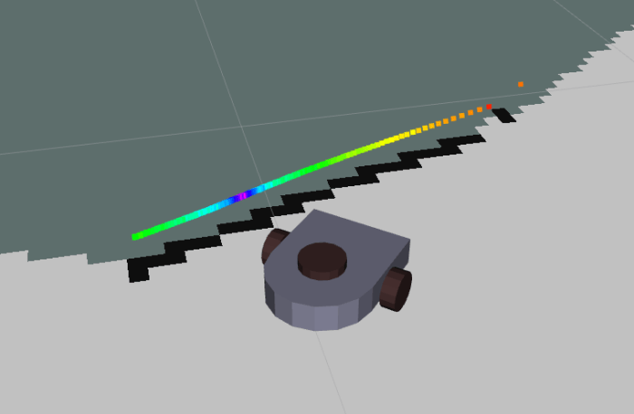
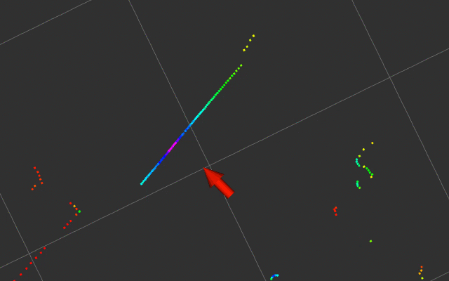
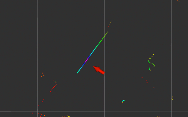
When I followed instructions for installation and running, the first error message was about configuring the serial port which was fine. But after that… nothing. No information published to /odom or /base_scan, and no response to command sent to /cmd_vel.

Digging into the source code, the first thing to catch my attention was that the code opened a serial port for communication but did not set provision for timeout. Any problem in serial communication will cause it to hang, which is exactly what it is doing now. Adding a timeout is a quick and easy way to test if this is actually related.

Existing:

self.port = serial.Serial(port,115200)

Modified:

self.port = serial.Serial(port,115200,timeout=0.01)

And that was indeed helpful, restoring nominal functionality to the ROS node. I could now drive the robot vacuum by sending commands to /cmd_vel and I can see a stream of data published to /odom and /base_scan.

I briefly contemplated being lazy and stopping there, but I thought I should try to better understand the failure. Onward to debugging!

Existing Neato Robot ROS Package Will Need Some Updating

Neato mini USB cable connection to laptopNow that we’ve got a pretty good handle on getting old Neato robot vacuums up and running, including talking to their brains via USB, it’s time to dig into the software side and explore its potential. I could adapt my SGVHAK rover code to control a Neato, but I think it’s more interesting to get my Neato up and running on ROS.

Unsurprisingly, there already exists a neato_robot ROS package for Neato. Equally unsurprisingly, it was maintained up to ROS Hydro and since abandoned. ROS releases are named alphabetically, meaning this code is three releases behind my installation of ROS Kinetic and a whopping five releases behind the current state of the art ROS Melodic.

But hey, it’s all open source, if I want to get it to function all I need to do is roll up my sleeves and get to work. Since it’s out of date, I think it’d be a bad idea to grab the pre built package. Instead I followed links to its source code repository (last updated October 2014) and cloned it into my local catkin workspace.

And continuing on the trend of not being surprised, this code did not work immediately. Publishing events to /cmd_vel topic did not elicit robot chassis movement, and subscribing to /odom or /base_scan received no data. Fortunately this node was written in Python, which I hope would be easier to debug than a ROS node written in C++. But either way, it’s time to dig in and figure out what it is doing and how that differs from what it is supposed to be doing.

Window Shopping BeagleBone Blue

Sawppy was a great ice breaker as I roamed through the expo hall of SCaLE 17x. It was certainly the right audience to appreciate such a project, even though there were few companies with products directly relevant to a hobbyist Mars rover. One notable exception, however is the BeagleBoard Foundation booth. As Sawppy drove by, the reception was: “Is that a Raspberry Pi? Yes it is. That should be a BeagleBone Blue!”

Beaglebone Blue 1600
BeagleBone Blue picture from Make.

With this prompt, I looked into BBBlue in more detail. At $80 it is significantly more expensive than a bare Raspberry Pi, but it incorporates a lot of robotics-related features that a Pi would require several HATs to reach parity.

All BeagleBoards offer a few advantages over a Raspberry Pi, which the BBBlue inherits:

  • Integrated flash storage, Pi requires a separate microSD card.
  • Onboard LEDs for diagnosis information.
  • Onboard buttons for user interaction – including a power button! It’s always personally grated me a Raspberry Pi has no graceful shutdown button.

Above and beyond standard BeagleBoards, the Blue adds:

  • A voltage regulator, which I know well is an extra component on a Pi.
  • On top of that, BBBlue can also handle charging a 2S LiPo battery! Being able to leave the battery inside a robot would be a huge convenience. And people who don’t own smart battery chargers wouldn’t need to buy one if all they do is use their battery with a BBBlue.
  • 8 PWM headers for RC-style servo motors.
  • 4 H-bridge to control 4 DC motors.
  • 4 Quadrature encoder inputs to know what those motors are up to.
  • 9-axis IMU (XYZ accelaration + XYZ rotation)
  • Barometer

Sadly, a BBBlue is not a great fit for Sawppy because it uses serial bus servos making all the hardware control features (8 PWM header, 4 motor control, 4 quadrature input) redundant. But I can definitely think of a few projects that would make good use of a BeagleBone Blue. It is promising enough for me to order one to play with.

Window Shopping AWS DeepRacer

At AWS re:Invent 2018 a few weeks ago, Amazon announced their DeepRacer project. At first glance it appears to be a more formalized version of DonkeyCar, complete with an Amazon-sponsored racing league to take place both online digitally and physically at future Amazon events. Since the time I wrote up a quick snapshot for Hackaday, I went through and tried to learn more about the project.

While it would have been nice to get hands-on time, it is still in pre-release and my application to join the program received a an acknowledgement that boils down to “don’t call us, we’ll call you.” There’s been no updates since, but I can still learn a lot by reading their pre-release documentation.

Based on the (still subject to change) Developer Guide, I’ve found interesting differences between DeepRacer and DonkeyCar. While they are both built on a 1/18th scale toy truck chassis, there are differences almost everywhere above that. Starting with the on board computer: a standard DonkeyCar uses a Raspberry Pi, but the DeepRacer has a more capable onboard computer built around an Intel Atom processor.

The software behind DonkeyCar is focused just on driving a DonkeyCar. In contrast DeepRacer’s software infrastructure is built on ROS which is a more generalized system that just happens to have preset resources to help people get up and running on a DeepRacer. The theme continues to the simulator: DonkeyCar has a task specific simulator, DeepRacer uses Gazebo that can simulate an environment for anything from a DeepRacer to a humanoid robot on Mars. Amazon provides a preset Gazebo environment to make it easy to start DeepRacer simulations.

And of course, for training the neural networks, DonkeyCar uses your desktop machine while DeepRacer wants you to train on AWS hardware. And again there are presets available for DeepRacer. It’s no surprise that Amazon wants people to build skills that are easily transferable to robots other than DeepRacer while staying in their ecosystem, but it’s interesting to see them build a gentle on-ramp with DeepRacer.

Both cars boil down to a line-following robot controlled by a neural network. In the case of DonkeyCar, the user trains the network to drive like a human driver. In DeepRacer, the network is trained via reinforcement learning. This is a subset of deep learning where the developer provides a way to score robot behavior, the higher the better, in the form of an reward function. Reinforcement learning trains a neural network to explore different behaviors and remember the ones that help it get a higher score on the developer-provided evaluation function. AWS developer guide starts people off with a “stay on the track” function which won’t work very well, but it is a simple starting point for further enhancements.

Based on reading through documentation, but before any hands-on time, the differences between DonkeyCar and DeepRacer serve different audiences with different priorities.

  • Using AWS machine learning requires minimal up-front investment but can add up over time. Training a DonkeyCar requires higher up-front investment in computer hardware for machine learning with TensorFlow.
  • DonkeyCar is trained to emulate behavior of a human, which is less likely to make silly mistakes but will never be better than the trainer. DeepRacer is trained to optimize reward scoring, which will start by making lots of mistakes but has the potential to drive in a way no human would think of… both for better and worse!
  • DonkeyCar has simpler software which looks easier to get started. DeepRacer uses generalized robot software like ROS and Gazebo that, while presets are available to simplify use, still adds more complexity than strictly necessary. On the flipside, what’s learned by using ROS and Gazebo can be transferred to other robot projects.
  • The physical AWS DeepRacer car is a single pre-built and tested unit. DonkeyCar is a DIY project. Which is better depends on whether a person views building their own car as a fun project or a chore.

I’m sure there are other differences that will surface with some hands-on time, I plan to return and look at AWS DeepRacer in more detail after they open it up to the public.

Xbox 360 Kinect Needs A Substitute Rover

It was pretty cool to see RTAB-Map build a 3D map of its environment using data generated by my hands waving a Xbox 360 Kinect around. However, that isn’t very representative of rover operation. When I wave it around manually, motions are mostly pan and tilt but not much translation. The optical flow of video feed from a rover traveling along the ground would be mostly dominated by forward travel, occasional panning as the vehicle turns, and limited tilt. So the next experiment is to put the Kinect on a rover to see how it acts.

This is analogous to what we did at SGVTech when I first brought in the LIDAR from a Neato vacuum: we placed on top of SGVHAK Rover and drove it around the shop to see what it sees. Unfortunately, the SGVHAK Rover is currently in the middle of an upgrade and disassembled on a workbench. We’ll need something else to stand in for a rover chassis. Behold, the substitute rover:

kinect with office chair simulating rover

Yes, that is a Xbox 360 Kinect sensor bar taped on top of an office chair. The laptop talking to the Kinect can sit on the chair easily enough, but the separate 12V power supply took a bit more work. I had two identical two-cell lithium battery packs. Wiring those two ~7.4V volt packs in series gave me ~14.8 volts, which fed into a voltage regulator bringing it down to 12V for the Kinect. The whole battery power contraption is visible in this picture taped to the laptop’s wrist rest next to the trackpad.

This gave us a wheeled platform for linear and rotational motion along the ground while keeping the Kinect at a constant height. This is more representative of the type of motion it will see mounted on a rover. Wheeling the chair around the shop, we would see the visual odometer performance is impressive, traveling in a line for about three meters resulted in only a few centimeters of error between its internal representation and reality.

We found this by turning the chair around to let the Kinect see where it came from and compare the newly plotted dots against those it plotted three meters ago. But this raised a new question: was it reasonable to expect that RTAB-Map algorithm match the new dots against the old? Using distance data to correct for odometer drift was one thing Phoebe could do in GMapping. I had hoped RTAB-Map would use new observations to correct for its own visual odometry drift. But instead, it started plotting features a few centimeters off from their original position, creating a “ghost” in point cloud data. Maybe I’m using RTAB-Map wrong somewhere… this is worrisome behavior that needs to be understood.

Xbox 360 Kinect and RTAB-Map: Handheld 3D Environment Scanning

I brought my modified Xbox 360 Kinect and my laptop to this week’s SGVTech meetup. My goal for the evening was to show everyone what can be done with an old game console accessory and publicly available open source code. And the best place to start showcasing RTAB-Map is to go through the very first tutorial: Handheld Mapping with RGB-D sensor.

When I installed OpenKinect on my Ubuntu laptop, I was pleasantly surprised that it was offered as part of Ubuntu software repository making installation trivial. I had half expected that I would have to download the source code and struggle to compile without errors.

Getting handheld RGB-D mapping up and running under ROS using RTAB-Map turned out to be almost as easy. They’re all available on ROS software repositories, again sparing me the headache of understanding and fixing compiler errors. That is, as long as a computer already has ROS Kinetic installed, which is admittedly a bit of work.

But if someone is starting with a working installation of ROS Kinetic on Ubuntu, they only need to install three packages via sudo apt install:

Once they are installed, follow instructions on RTAB-Map handheld RGB-D mapping tutorial to execute two ROS launch files. First one launches the ROS node to match the sensor device (in my case the Xbox 360 Kinect), second one launch RTAB-Map itself along with a visualization GUI.

I had fun scanning the shop environment where we hold our meetups. I moved the sensor around, both panning left-right and up-down, to get data from one side of the room. RTAB-Map created a pretty decent 3D representation of the shop. Here’s a camera view of one experiment. The Kinect is sitting on the workbench behind the laptop screen. The visualization GUI has the raw video image (upper left), an image with dots highlighting the features RTAB-Map is tracking (lower left), and a big window with 3D point cloud compilation of Kinect data.

workshop shelves 3d reconstruction - camera

Here’s the screenshot. It is even more impressive in person because we could interact with the point cloud window, rotate and zoom in 3D space to see the area from angles that the Kinect was never at. Speaking of which, look at the light teal line drawn in the lower right: this represents what RTAB-Map reconstructed as the path (in three dimensional space) I waved the Kinect through.

Workshop Shelves 3D reconstruction - screencap.jpg

RTAB-Map is a lot of fun to play with, and shows huge potential for robot project applications.

Trying RTAB-Map To Process Xbox 360 Kinect Data

xbox 360 kinect with modified plugs 12v usb
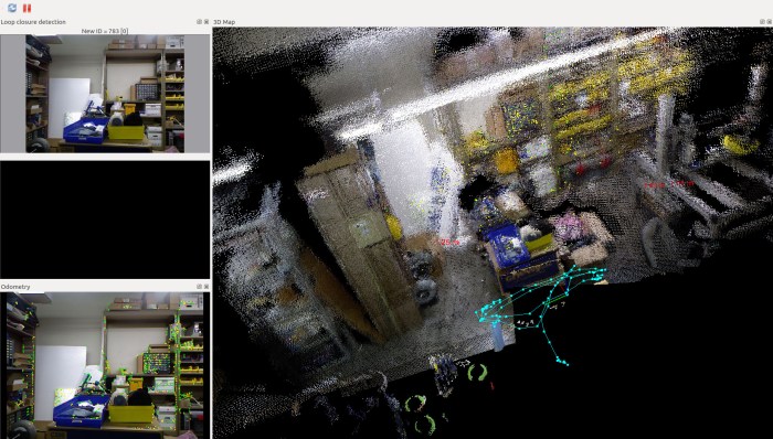
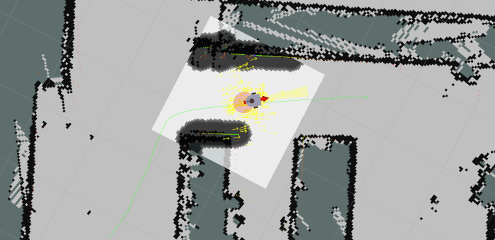
Depth sensor data from a Xbox 360 Kinect might be imperfect, but it is good enough to proceed with learning about how a machine can make sense of its environment using such data. This is an area of active research with lots of options on how I can sample the current state of the art. What looks the most interesting to me right now is RTAB-Map, from Mathieu Labbé of IntRoLab at Université de Sherbrooke (Quebec, Canada.)

rtab-mapRTAB stands for Real-Time Appearance-Based, which neatly captures the constraint (fast enough to be real-time) and technique (extract interesting attributes from appearance) of how the algorithm approaches mapping an environment. I learned of this algorithm by reading the research paper behind a Hackaday post of mine. The robot featured in that article used RTAB-Map to generate its internal representation of its world.

The more I read about RTAB-Map, the more I liked what I found. Its home page lists events dating back to 2014, and the Github code repository show updates as recently as two days ago. It is encouraging to see continued work on this project, instead of something that was abandoned years ago when its author graduated. (Unfortunately quite common in the ROS ecosystem.)

Speaking of ROS, RTAB-Map itself is not tied to ROS, but the lab provides a rtab-ros module to interface with ROS. Its Github code repository has also seen recent updates, though it looks like a version for ROS Melodic has yet to be generated. This might be a problem later… but right now I’m still exploring ROS using Kinetic so I’m OK in the short term.

As for sensor support, RTAB-Map supports everything I know about, and many more that I don’t. I was not surprised to find support for OpenNI and OpenKinect (freenect). But I was quite pleased to see that it also supports the second generation Xbox One Kinect via freenect2. This covers all the sensors I care about in the foreseeable future.

The only downside is that RTAB-Map requires significantly more computing resources than what I’ve been playing with to date. This was fully expected and not a criticism of RTAB-Map. I knew 3D data would far more complex to process, but I didn’t know how much more. RTAB-Map will be my first solid data point. Right now my rover Sawppy is running on a Raspberry Pi 3. According to RTAB-Map author, a RPi 3 could only perform updates four to five times a second. Earlier I had outlined the range of computing power I might summon for a rover brain upgrade. If I want to run RTAB-Map at a decent rate, it looks like I have to go past Chromebook level of hardware to Intel NUC level of power. Thankfully I don’t have to go to the expensive realm of NVIDIA hardware (either a Jetson board or a GPU) just yet.

Xbox 360 Kinect Driver: OpenNI or OpenKinect (freenect)?

The Kinect sensor bar from my Xbox 360 has long been retired from gaming duty. For its second career as robot sensor, I have cut off its proprietary plug and rewired it for computer use. Once I’ve verified the sensor bar is electrically compatible with a computer running Ubuntu, the first order of business was to turn fragile test connections into properly soldered wires protected by heat shrink tube. Here’s my sensor bar with its new standard USB 2.0 connector and a JST-RCY connector for 12 volt power.

xbox 360 kinect with modified plugs 12v usb

With the electrical side settled, attention turns to software. The sensor bar can tell the computer it is a USB device, but we’ll need additional driver software to access all the data it can provide. I chose to start with the Xbox 360 Kinect because of its wider software support, which means I have multiple choices on which software stack to work with.

OpenNI is one option. This open source SDK is still around thanks to Occipital, one of the companies that partnered with PrimeSense. PrimeSense was the company that originally developed the technology behind Xbox 360 Kinect sensor, but they have since been acquired by Apple and their technology incorporated into the iPhone X. Occipital itself is still in the depth sensor business with their Structure sensor bar. Available standalone or incorporated into products like Misty.

OpenKinect is another option. It doesn’t have a clear corporate sponsor like OpenNI, and seems to have its roots in the winner of the Adafruit contest to create an open source Kinect driver. Confusingly, it is also sometimes called freenect or variants thereof. (Its software library is libfreenect, etc.)

Both of these appear to still be receiving maintenance updates, and both have been used a lot of cool Kinect projects outside of Xbox 360 games. Ensuring there will be a body of source code available as reference for using either. Neither are focused on ROS, but people have written ROS drivers for both OpenNI and OpenKinect (freenect). (And even an effort to rationalize across both.)

One advantage of OpenNI is that it provides an abstraction layer for many different depth cameras built on PrimeSense technology, making code more portable across different hardware. This does not, however, include the second generation Xbox One Kinect, as that was built with a different (not PrimeSense) technology.

In contrast, OpenKinect is specific to the Xbox 360 Kinect sensor bar. It provides access to parts beyond the PrimeSense sensor: microphone array, tilt motor, and accelerometer.  While this means it doesn’t support the second generation Xbox One Kinect either, there’s a standalone sibling project libfreenect2 for meeting that need.

I don’t foresee using any other PrimeSense-based sensors, so OpenNI’s abstraction doesn’t draw me. The access to other hardware offered by OpenKinect does. Plus I do hope to upgrade to a Xbox One Kinect in the future, so I decided to start my Xbox 360 Kinect experimentation using OpenKinect.

ROS In Three Dimensions: Starting With Xbox 360 Kinect

The long-term goal driving my robotics investigations is to build something that has an awareness of its environment, and intelligently plan actions within it. (This is a goal shared by many other members of RSSC as well.) Building Phoebe gave me an introduction to ROS running in two dimensions, and now I have ambition to graduate to three. A robot working in three dimensions need a sensor that works in three dimensions, so where I’m going to start.

Phoebe started with a 2D laser scanner purchased off eBay that I learned to get up and running in ROS. Similarly, the cheapest 3D sensor that can be put on a ROS robot are repurposed Kinect sensor bars from Xbox game consoles. Even better, since I’ve been a Xbox gamer (more specifically a Halo and Forza gamer) I don’t need to visit eBay. I have my own Kinect to draft into this project. In fact, I have more than one: I have both the first generation Kinect sensor accessory for Xbox 360, and the second generation that was released alongside Xbox One.

xbox 360 kinect and xbox one kinect

The newer Xbox One Kinect is a superior sensor with a wider field of view, higher resolution, and better precision. But that doesn’t necessarily make it the best choice to start off with, because hardware capability is only part of the story.

When the Xbox 360 Kinect was launched, it was a completely novel new device offering depth sensing at a fraction of the price of existing depth sensors. There was a lot of enthusiasm both in the context of video gaming and hacking them to be used outside of Xbox 360 games. Unfortunately, the breathless hype wrote checks that the reality of a low-cost depth camera couldn’t quite cash. By the time Xbox One launched with an updated Kinect, interest had waned and far fewer open source projects aimed to work with a second generation Kinect.

The superior capabilities of the second generation sensor bar also brought downsides: it required more data bandwidth and hence a move to USB 3.0. At the time, USB 3.0 ecosystem was still maturing and new Kinect had problems working with certain USB 3.0 implementations. Even if the data could get into a computer, the sheer amount of it placed more demands on processing code. When coupled with reduced public interest, it meant software support for the second generation Kinect is less robust. A web search found a lot of people who encountered problems trying to get their second generation bar to work.

In the interest of learning the ropes and getting an introduction to the world of 3D sensing, I decided a larger and more stable software base is more interesting than raw hardware capabilities. I’ll use the first generation Xbox 360 Kinect sensor bar to climb the learning curve of building a three-dimensional solution in ROS. Once that is up and running, I can try to tame the more finicky second generation Kinect.

ROS In Three Dimensions: Navigation and Planning Will Be Hard

backyard sawppy 1600
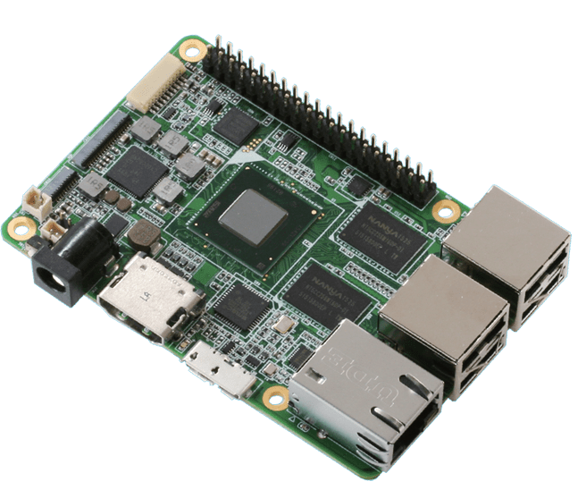
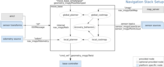
At this point my research has led me to ROS modules RTAB-Map which will create a three dimensional representation of a robot’s environment. It seems very promising… but building such a representation is only half the battle. How would a robot make good use of this data? My research has not yet uncovered applicable solutions.

The easy thing to do is to fall back to two dimensions, which will allow the use of standard ROS navigation stack. The RTAB-Map ROS module appears to make the super easy, with the option to output a two dimension occupancy grid just like what navigation wants. It is a baseline for handling indoor environments, navigating from room to room and such.

But where’s the fun in that? I could already do that with a strictly two-dimensional Phoebe. Sawppy is a six wheel rover for handling rougher terrain and it would be far preferable to make Sawppy autonomous with ROS modules that can understand and navigate outdoor environments. But doing so successfully will require solving a lot of related problems that I don’t have answers yet.

We can see a few challenges in the picture of Sawppy in a back yard environment:

  • Grass is a rough surface that would be very noisy to robot sensors due to individual blades of grass. With its six wheel drivetrain, Sawppy can almost treat grassy terrain as flat ground. But not quite! There are hidden dangers – like sprinkler heads – which could hamper movement and should be considered in path planning.
  • In the lower right corner we can see transition from grass to flat red brick. This would show as a transition to robot sensors as well, but deciding whether that transition is important will need to be part of path planning. It even introduces a new consideration in the form of direction: Sawppy has no problem dropping from grass to brick, but it takes effort to climb from brick back on to grass. This asymmetry in cost would need to be accounted for.
  • In the upper left corner we see a row of short bricks. An autonomous Sawppy would need to evaluate those short bricks and decide if they could be climbed, or if they are obstacles to be avoided. Experimentally I have found that they are obstacles, but how would Sawppy know that? Or more interestingly: how would Sawppy perform its own experiment autonomously?

So many interesting problems, so little time!

(Cross-posted to Hackaday.io)

ROS In Three Dimensions: Data Structure and Sensor

rosorg-logo1One of the ways a TurtleBot makes ROS easier and more approachable for beginners is by simplifying a robot’s world into two dimensions. It’s somewhat like the introductory chapters of a physics textbook, where all surfaces are friction-less and all collisions are perfectly inelastic. The world of a TurtleBot is perfectly flat and all obstacles have an infinite height. This simplification allows the robot’s environment to be represented as a 2D array called an occupancy grid.

Of course, the real world is more complicated. My TurtleBot clone Phoebe encountered several problems just trying to navigate my home. The real world do not have flat floors and obstacles come in all shapes, sizes, and heights. Fortunately, researchers have been working on problems encountered by robots venturing outside the simplified world, it’s a matter of reading research papers and following their citation links to find the tools.

One area of research improves upon the 2D occupancy grid by building data structures that can represent a robot’s environment in 3D. I’ve found several papers that built upon the octree concept, so that seems to be a good place to start.

But for a robot to build a representation of its environment in 3D, it needs 3D sensors. Phoebe’s Neato vacuum LIDAR works in a simplified 2D world but won’t cut it anymore in a 3D world. The most affordable entry point here is the Microsoft Kinect sensor bar from an old Xbox 360, which can function as a RGBD (red + blue + green + depth) input source for ROS.

Phoebe used Gmapping for SLAM, but that takes 2D laser scan data and generates a 2D occupancy grid. Searching for a 3D SLAM algorithm that can digest RGBD camera data, I searched for “RGBD SLAM” that led immediately to this straightforwardly named package. But of course, that’s not the only one around. I’ve also come across RTAB-Map which seems to be better maintained and updated for recent ROS releases. And best of all, RTAB-Map has the ability to generate odometry data purely from the RGBD input stream, which might allow me to bypass the challenges of calculating Sawppy’s chassis odometry from unreliable servo angle readings.

(Cross-posted to Hackaday.io)

Sawppy on ROS: Open Problems

A great side effect of giving a presentation is that it requires me to gather my thoughts in order to present them to others. Since members of RSSC are familar with ROS, I collected my scattered thoughts on ROS over the past few weeks and condensed the essence into a single slide that I’ve added to my presentation.

backyard sawppy 1600

From building and running my Phoebe robot, I learned about the basics of ROS using a two-wheeled robot on flat terrain. Sticking to 2D simplifies a lot of robotics problems and I thought it would help me expand to a six-wheeled rover to rough terrain. Well, I was right on the former but the latter is still a big step to climb.

The bare basic responsibilities of a ROS TurtleBot chassis (and derivatives like Phoebe) is twofold: subscribe to topic /cmd_vel and execute movement commands published to that topic, and from the resulting movement, calculate and publish odometry data to topic /odom.

Executing commands sent to /cmd_vel is relatively straightforward when Sawppy is on level ground. It would not terribly different from existing code. The challenge comes from uneven terrain with unpredictable traction. Some of Sawppy’s wheels might slip and resulting motion might be very different from what was commanded. My experience with Phoebe showed that while it is possible to correct for minor drift, major sudden unexpected shifts in position or orientation (such as when Phoebe runs into an unseen obstacle) throws everything out of whack.

Given the potential for wheel slip on uneven terrain, calculating Sawppy odometry is a challenge. And that’s before we consider another problem: the inexpensive serial bus servos I use do not have fine pitched rotation encoders, just a sensor for servo angle that only covers ~240 of 360 degrees. While I would be happy if it just didn’t return any data when out of range, it actually returns random data. I haven’t yet figured out a good way to filter the signal out of the noise, which would be required to calculate odometry.

And these are just challenges within the chassis I built, there’s more out there!

(Cross-posted to Hackaday.io)

Robot Brain Candidate: Up Board

When I did my brief survey of potential robotic brains earlier, I was dismissive of single-board computers competing with the Raspberry Pi. Every one I knew about had sales pitches about superior performance relative to the Pi, but none could match the broad adoption and hence software library support of a Raspberry Pi. At the time the only SBC I thought might be worthwhile were the Nvidia Jetson boards with specialized hardware. Other than that, I believed the growth path for robot brains that can run ROS is pretty much restricted to x64-based platforms like Chromebooks, Intel NUCs, and full-fledged laptop computers.

What I didn’t know at the time was that someone has actually put an Intel CPU on a Raspberry Pi sized circuit board computer: the Up board.

UPSlide3Right-EVT-3
Image from http://www.up-board.org

Well, now. This is interesting!

At first glance they even worked to keep the footprint of a Raspberry Pi, including the 40-pin GPIO headers and USB, Ethernet, and HDMI ports. However, the power and audio jacks are different, and the camera and display headers are gone.

It claims to run Windows 10, though it’s not clear if they meant the restricted IoT edition or the full desktop OS. Either way it shouldn’t be too much of a hurdle to get Ubuntu on one of these things running ROS. While the 40-pin GPIO claims to match a Raspberry Pi, it’s not clear how they are accessed from an operation system not designed for a Raspberry Pi.

And even more encouragingly: the makers of this board is not content to be an one-hit wonder, they’ve branched out to other tiny form factors that give us the ability to run x86 software.

The only downside is that the advantage is from size, not computational power. None of the CPUs I’ve seen mentioned are very fast. At best, they are roughly equivalent to the one in my Dell Inspiron 11 3180, just tinier. Still, these board offer some promising approaches to robot hardware. It’s worth revisiting if I get stuff running on my cheap Dell but need a smaller board.

ROS Notes: Hector SLAM Creates 2D Map From 3D Motion

rosorg-logo1While I was trying to figure out how to best declare ROS coordinate transform frames of reference for Phoebe, I came across a chart on hector_slam page detailing multiple frames of reference for a robot base. It turned out to be unnecessary for the GMapping algorithm I’m currently using for Phoebe, but it made me curious enough to take a closer look.

I have yet to try using hector_slam on Phoebe. I’m only aware of it as an alternative SLAM algorithm to gmapping. The two systems make different trade-offs and one might work better than the other under different circumstances. I knew hector_slam was the answer when some people asked if it’s possible to perform SLAM without wheel odometry data, but I knew there had to be more to it. The requirements for multiple frames is my entry point to understand what’s going on.

My key takeaway after reading the paper: gmapping is designed for a robot working strictly in flat 2D. In contrast, hector_slam is designed for platforms that may move about in 3 dimensions. Not just flat 2D, but also ground vehicles traversing rough terrain (accounting for pitch and roll motions) and even robotic aircraft. Not requiring wheel odometry data is obvious a big part of supporting air vehicles!

But if hector_slam is so much more capable, why isn’t everyone using it? That’s when we get to the flip side: for good results it requires a LIDAR with high scan rate and high accuracy. Locating robot position without wheel odometry is made possible by frequent distance data refreshes (40 Hz was mentioned in the paper). Unfortunately, this also dims prospect for use aboard Phoebe as the Neato LIDAR is neither fast (4 Hz) or accurate.

And despite its capability to process 3D data from robotic platforms that have 3D motion, hector_slam generates a 2D map. This implies the mapping navigation algorithms will not have access to captured 3D data. Plotting a path with this data, a short and rough route would look better than a longer smooth flat route. This makes me skeptical hector_slam will be interesting for Sawppy, but that’s to be determined later.


Phoebe Is Navigating Autonomously

I’ve been making progress (slowly but surely) thorough the ROS navigation stack tutorial to get it running on Phoebe, and finally reached the finish line.

After all the configuration YAML files were created, they were tied together into a launch file as parameters to the ROS node move_base. For now I’m keeping the pieces in independent launch files, so move_base is ran independently of Phoebe’s chassis functionality launch file and AMCL (launched using its default amcl_diff.launch).

After they were all running, a new RViz configuration was created to visualize local costmap and amcl particle cloud. And it was a huge mess! I was disheartened for a few seconds before I remembered seeing a similar mess when I first looked at navigation on a Gazebo simulation of TurtleBot 3 Burger. Before anything would work, I had to set the initial “2D Pose Estimate” to locate Phoebe on the map.

Once that was done, I set a “2D Nav Goal” via RViz, and Phoebe started moving! Looking on RViz I could see the map along with LIDAR scan plots and Phoebe’s digital representation from URDF. Those are all familiar from earlier. New to the navigation map is a planned path plotted in green taking account of the local cost map in gray. AMCL contributed the rest of the information on screen, with individual estimates drawn as little yellow arrows and estimated position in red.

Phoebe Nav2D 2

It’s pretty exciting to have a robot with basic intelligence for path planning, and not just a fancy remote control car.

Of course, there’s a lot of tuning to be done before things actually work well. Phoebe is super cautious and conservative about navigating obstacles, exhibiting a lot of halting and retrying behavior in narrower passageways even when there are still 10-15cm of clearance on each side. I’m confident there are parameter I could tune to improve this.

Less obvious are what I need to adjust to increase Phoebe’s confidence in relatively wide open areas, Phoebe would occasionally brake to a halt and hunt around a bit before resuming travel even when there’s plenty of space. I didn’t see an obstacle pop up on the local costmap, so it’s not clear what triggered this behavior.

(Cross-posted to Hackaday.io)

Navigation Stack Setup for Phoebe

rosorg-logo1Section 1 “Robot Setup” of this ROS Navigation tutorial page confirmed Phoebe met all the basic requirements for the standard ROS navigation stack. Section 2 “Navigation Stack Setup” is where I need to tell that navigation stack how to run on Phoebe.

I had already created a ROS package for Phoebe earlier to track all of my necessary support files, so getting navigation up and running is a matter of creating a new launch file in my existing directory for launch files. To date all of my ROS node configuration has been done in the launch file, but ROS navigation requires additional configuration files in YAML format.

First up in the tutorial were the configuration values common for both local and global costmap. This is where I saw the robot footprint definition, a little sad it’s not pulled from the URDF I just put together. Since Phoebe’s footprint is somewhat close to a circle, I went with the robot_radius option instead of declaring a footpring with an array of [x,y] coordinates. The inflation_radius parameter sounds like an interesting one to experiment with later pending Phoebe performance. The observation_sources parameter is interesting – it implies the navigation stack can utilize multiple sources simultaneously. I want to come back later and see if it can use a Kinect sensor for navigation. For now, Phoebe has just a LIDAR so that’s how I configured it.

For global costmap parameters, the tutorial values look equally applicable to Phoebe so I copied them as-is. For the local costmap, I reduced the width and height of the costmap window, because Phoebe doesn’t travel fast enough to need to look at 6 meters of surroundings, and I hoped reducing to 2 meters would reduce computation workload.

For base local planner parameters, I reduced maximum velocity until I have confidence Phoebe isn’t going to get into trouble speeding. The key modification here from tutorial values is changing holonomic_robot from true to false. Phoebe is a differential drive robot and can’t strafe sideways as a true holonomic robot can.

The final piece of section 2 is AMCL configuration. Earlier I’ve tried running AMCL on Phoebe without specifying any parameters (use defaults for everything) and it seemed to run without error messages, but I don’t yet have the experience to tell what good AMCL behavior is versus bad. Reading this tutorial, I see the AMCL package has pre-configured launch files. The tutorial called up amcl_omni.launch. Since Phoebe is a differential drive robot, I should use amcl_diff.launch instead. The RViz plot looks different than when I ran AMCL with all default parameters, but again, I don’t yet have the experience to tell if it’s an improvement or not. Let’s see how this runs before modifying parameters.

(Cross-posted to Hackaday.io.)

Checking If Phoebe Meets ROS Navigation Requirements

Now that basic coordinate transform frames have been configured with help of URDF and robot state publisher, I moved on to the next document: robot setup page. This one is actually listed slightly out of order list item on ROS navigation page, third behind the Basic Navigation Tuning Guide. I had started reading the “Tuning Guide” and saw that, in that introduction, the tuning guide assumes people have read the robot setup page. It’s not clear why they are out of order, but clearly robot setup needs to come first.

Right up front in Section 1 “Robot Setup” was a very helpful diagram labelled “Navigation Stack Setup” showing major building blocks for an autonomously navigating ROS robot. Even better, these blocks are color-coded as to their source. White blocks are part of the ROS navigation stack, gray parts are optional components outside of that stack, and blue indicates robot-specific code to interface with navigation stack.

overview_tf
Navigation Stack Setup diagram from ROS documentation

This gives me a convenient checklist to make sure Phoebe has everything necessary for ROS navigation. Clockwise from the right, they are:

  • Sensor source – check! Phoebe has a Neato LIDAR publishing laser scan sensor messages.
  • Base controller – check! Phoebe has a Roboclaw ROS node executing movement commands.
  • Odometry source – check! This is also provided by the Roboclaw ROS node reading from encoders.
  • Sensor transforms – check! This is what we just updated, from a hard-coded published transform to one published by robot state publisher based on information in Phoebe’s URDF.

That was the easy part. Section 2 was more opaque to this ROS beginner. It gave an overview of the configuration necessary for a robot to run navigation, but the overview assumes a level of ROS knowledge that’s at the limit of what I actually have in my head right now. It’ll probably take a few rounds of trial and error before I get everything up and running.

(Cross-posted to Hackaday.io)

Phoebe Digital Avatar in RViz

Now that Phoebe URDF has been figured out, it has been added to RViz visualization of Phoebe during GMapping runs. Before this point, Phoebe’s position and orientation (called a ‘pose‘ in ROS) is represented by a red arrow on the map. It’s been sufficient to get us this far, but a generic arrow is not enough for proper navigation because it doesn’t represent the space occupied by Phoebe. Now, with the URDF, the volume of space occupied by Phoebe is also visually represented on the map.

This is important for a human operator to gauge whether Phoebe can fit in certain spaces. While I was driving Phoebe around manually, it was a guessing game whether the red arrow will fit through a gap. Now with Phoebe’s digital avatar in the map, it’s a lot easier to gauge clearance.

I’m not sure if the ROS navigation stack will use Phoebe’s URDF in the same way. The primary reason the navigation tutorial pointed me to URDF is to get Phoebe’s transforms published properly in the tf tree using the robot state publisher tool. It’s pretty clear robot footprint information will be important for robot navigation for the same reason it was useful to human operation, I just don’t know if it’s the URDF doing that work or if I’ll end up defining robot footprint some other way. (UPDATE: I’ve since learned that, for the purposes of ROS navigation, robot footprint is defined some other way.)

In the meantime, here’s Phoebe by my favorite door to use for distance reference and calibration.

Phoebe By Door Posing Like URDF

And here’s the RViz plot, showing a digital representation of Phoebe by the door, showing the following:

  • LIDAR data in the form of a line of rainbow colored dots, drawn at the height of the Neato LIDAR unit. Each dot represents a LIDAR reading, with color representing the intensity of each return signal.
  • Black blocks on the occupancy map, representing space occupied by the door. Drawn at Z height of zero representing ground.
  • Light gray on the occupancy map representing unoccupied space.
  • Dark gray on the occupancy map representing unexplored space.

Phoebe By Door

(Cross-posted to Hackaday.io)

Next Phoebe Project Goal: ROS Navigation

rosorg-logo1When I started working on my own TurtleBot variant (before I even decided to call it Phoebe) my intention was to build a hardware platform to get first hand experience with ROS fundamentals. Phoebe’s Hackaday.io project page subtitle declared itself as a ROS robot for <$250 capable of SLAM. Now that Phoebe can map surroundings using standard ROS SLAM library ‘gmapping‘, that goal has been satisfied. What’s next?

One disappointment I found with existing ROS SLAM libraries is that the tutorials I’ve seen (such as this and this) expect a human to drive the robot during mapping. I had incorrectly assumed the robot would autonomously exploring its space, but “simultaneous location and mapping” only promises location and mapping – nothing about deciding which areas to map, and how to go about it. That is left to the human operator.

When I played with SLAM code earlier, I decided against driving the robot manually and instead invoked an existing module that takes a random walk through available space. A search on ROS Answers web site for something more sophisticated than a random walk resulted in multiple pointers to the explore module, but that code hasn’t been maintained since ROS “groovy” four versions ago. So one path forward is to take up the challenge of either update explore or write my own explorer.

That might be interesting, but once a map is built, what do we do with it? The standard ROS answer is the robot navigation stack. This collection of modules is what gives a ROS robot the ability to plan a path through a map, watch its progress through that plan, and update the plan in reaction to unexpected elements in the environment.

At the moment I believe it would be best to learn about the standard navigation stack and getting that up and running on Phoebe. I might return to the map exploration problem later, and if so, seeing how map data is used for navigation will give me better insights into what would make a better map explorer.

(Cross-posted to Hackaday.io)

Robot Disorientation Traced To Timing Mismatch

Once the Roboclaw ROS Node‘s wheel parameters were updated to match the new faster motors, Phoebe went on a mapping run. And the results were terrible! This is not a complete surprise. Based on previous experimentation with this LIDAR module, I’ve seen its output data distorted by motion. It doesn’t take a lot of motion – even a normal human walking pace is enough to cause visible distortion. So now that Phoebe’s motors are ten times faster than before, that extra speed also adds extra distortion.

While this is a problem, it might not be the only problem behind the poor map. I decided to dig into an anomaly I noticed while using RViz to calibrate wheel data against LIDAR data: there’s some movement that can’t be entirely explained by a LIDAR spinning at 240 RPM.

The idea behind this odometry vs. LIDAR plot on RViz is to see if wheel odometry data agrees with LIDAR data. My favorite calibration surface is a door – it is a nice flat surface for LIDAR signal return, and I could swing the door at various angles for testing. In theory, when everything lines up, movement in the calculated odometry would match LIDAR observed behavior, and everything that is static in the real world (like the door) would be static in the plot as well.

In order to tune the base_width parameter, I looked at the position of the door before turning, and position after turning. Adjusting base_width until they line up, indicating odometry matches LIDAR. But during the turn, the door moved relative to the robot before finishing at the expected position.

When Phoebe started turning (represented by red arrow) the door jumped out of position. After Phoebe stopped turning, the door snapped back to position. This means non-moving objects appear to the robot as moving objects, which would confuse any mapping algorithm.

Odom LIDAR Mismatch No Hack

I chased down a few dead ends before realizing the problem is a timing issue: the timestamp on the LIDAR data messages don’t line up with the timestamp on odometry messages. At the moment I don’t have enough data to tell who is at fault, the LIDAR node or the Roboclaw node, just that there is a time difference. Experimentation indicated the timing error is roughly on the order of 100 milliseconds.

Continuing the experiment, I hard-coded a 100ms timestamp delta. This is only a hack which does not address the underlying problem. With this modification, the door still moves around but at least it doesn’t jump out of place as much.

Odom LIDAR Mismatch 100ms hack

This timing error went unnoticed when Phoebe was crawling extremely slowly. But at Phoebe’s higher speed this timing error could not longer be ignored. Ideally all of the objects on the RViz plot would stay still, but we clearly see nonuniform distortion during motion. There may be room for further improvement, but I don’t expect I’ll ever get to ideal performance with such an inexpensive LIDAR unit. Phoebe may end up just having to go slowly while mapping.

(Cross-posted to Hackaday.io)