Trying RTAB-Map To Process Xbox 360 Kinect Data

xbox 360 kinect with modified plugs 12v usb
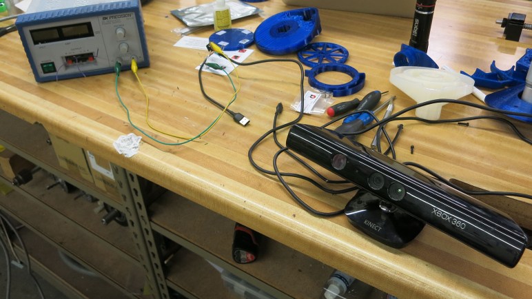
Depth sensor data from a Xbox 360 Kinect might be imperfect, but it is good enough to proceed with learning about how a machine can make sense of its environment using such data. This is an area of active research with lots of options on how I can sample the current state of the art. What looks the most interesting to me right now is RTAB-Map, from Mathieu Labbé of IntRoLab at Université de Sherbrooke (Quebec, Canada.)

rtab-mapRTAB stands for Real-Time Appearance-Based, which neatly captures the constraint (fast enough to be real-time) and technique (extract interesting attributes from appearance) of how the algorithm approaches mapping an environment. I learned of this algorithm by reading the research paper behind a Hackaday post of mine. The robot featured in that article used RTAB-Map to generate its internal representation of its world.

The more I read about RTAB-Map, the more I liked what I found. Its home page lists events dating back to 2014, and the Github code repository show updates as recently as two days ago. It is encouraging to see continued work on this project, instead of something that was abandoned years ago when its author graduated. (Unfortunately quite common in the ROS ecosystem.)

Speaking of ROS, RTAB-Map itself is not tied to ROS, but the lab provides a rtab-ros module to interface with ROS. Its Github code repository has also seen recent updates, though it looks like a version for ROS Melodic has yet to be generated. This might be a problem later… but right now I’m still exploring ROS using Kinetic so I’m OK in the short term.

As for sensor support, RTAB-Map supports everything I know about, and many more that I don’t. I was not surprised to find support for OpenNI and OpenKinect (freenect). But I was quite pleased to see that it also supports the second generation Xbox One Kinect via freenect2. This covers all the sensors I care about in the foreseeable future.

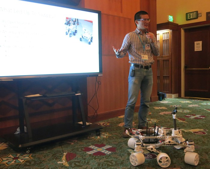
The only downside is that RTAB-Map requires significantly more computing resources than what I’ve been playing with to date. This was fully expected and not a criticism of RTAB-Map. I knew 3D data would far more complex to process, but I didn’t know how much more. RTAB-Map will be my first solid data point. Right now my rover Sawppy is running on a Raspberry Pi 3. According to RTAB-Map author, a RPi 3 could only perform updates four to five times a second. Earlier I had outlined the range of computing power I might summon for a rover brain upgrade. If I want to run RTAB-Map at a decent rate, it looks like I have to go past Chromebook level of hardware to Intel NUC level of power. Thankfully I don’t have to go to the expensive realm of NVIDIA hardware (either a Jetson board or a GPU) just yet.

Xbox 360 Kinect Depth Sensor Data via OpenKinect (freenect)

I want to try using my Xbox 360 Kinect as a robot sensor. After I’ve made the necessary electrical modifications, I decided to try to talk to my sensor bar via OpenKinect (a.k.a. freenect a.k.a. libfreenect) driver software. Getting it up and running on my Ubuntu 16.04 installation was surprisingly easy: someone has put in the work to make it a part of standard Ubuntu software repository. Whoever it was, thank you!

Once installed, though, I wasn’t sure what to do next. I found documentation telling me to launch a test/demonstration viewer application called glview. That turned out to be old information, the test app is actually called freenect-glview. Also, it is no longer added to the default user search path. I have to launch it with the full path /usr/bin/freenect-glview.

Once I got past that minor hurdle, I have on my screen a window that showed two video feeds from my Kinect sensor: on the left, depth information represented by colors. And on the right, normal human vision color video. Here’s my Kinect pointed at its intended home: on board my rover Sawppy.

freenect-glview with sawppy

This gave me a good close look at Kinect depth data. What’s visible and represented by color is pretty good, but the black areas worry me. They represent places where the Kinect was not able to extract depth information. I didn’t expect it to be able to pick out fine surface details of Sawppy components, but I did expect it to see the whole chassis in some form. This was not the case, with areas of black all over Sawppy’s chassis.

Some observations of what a Xbox 360 Kinect could not see:

  • The top of Sawppy’s camera mast. Neither the webcam nor the 3D-printed mount for that camera. This part is the most concerning one because I have no hypothesis why.
  • The bottom of Sawppy’s payload bay. This is unfortunate but understandable: it is a piece of laser cut acrylic which would reflect Kinect’s projected pattern away from the receiving IR camera.
  • The battery pack in rear has a smooth clear plastic package and would also not reflect much back to the camera.
  • Wiring bundles are enclosed in a braided sleeve. It would scatter the majority of IR pattern and those that make it to the receiving camera would probably be jumbled.

None of these are deal-breakers on their own, they’re part of the challenges of building a robot that functions outside of a controlled environment. In addition to those, I’m also concerned about the frame-to-frame inconsistency of depth data. Problematic areas are sometimes visible for a frame and disappear in the next. The noisiness of this information might confuse a robot trying to make sense of its environment with this data. It’s not visible in the screenshot above, but here’s an animated GIF showing a short snippet for illustration:

kinect-looking-at-sawppy-inconsistencies

Xbox 360 Kinect Driver: OpenNI or OpenKinect (freenect)?

The Kinect sensor bar from my Xbox 360 has long been retired from gaming duty. For its second career as robot sensor, I have cut off its proprietary plug and rewired it for computer use. Once I’ve verified the sensor bar is electrically compatible with a computer running Ubuntu, the first order of business was to turn fragile test connections into properly soldered wires protected by heat shrink tube. Here’s my sensor bar with its new standard USB 2.0 connector and a JST-RCY connector for 12 volt power.

xbox 360 kinect with modified plugs 12v usb

With the electrical side settled, attention turns to software. The sensor bar can tell the computer it is a USB device, but we’ll need additional driver software to access all the data it can provide. I chose to start with the Xbox 360 Kinect because of its wider software support, which means I have multiple choices on which software stack to work with.

OpenNI is one option. This open source SDK is still around thanks to Occipital, one of the companies that partnered with PrimeSense. PrimeSense was the company that originally developed the technology behind Xbox 360 Kinect sensor, but they have since been acquired by Apple and their technology incorporated into the iPhone X. Occipital itself is still in the depth sensor business with their Structure sensor bar. Available standalone or incorporated into products like Misty.

OpenKinect is another option. It doesn’t have a clear corporate sponsor like OpenNI, and seems to have its roots in the winner of the Adafruit contest to create an open source Kinect driver. Confusingly, it is also sometimes called freenect or variants thereof. (Its software library is libfreenect, etc.)

Both of these appear to still be receiving maintenance updates, and both have been used a lot of cool Kinect projects outside of Xbox 360 games. Ensuring there will be a body of source code available as reference for using either. Neither are focused on ROS, but people have written ROS drivers for both OpenNI and OpenKinect (freenect). (And even an effort to rationalize across both.)

One advantage of OpenNI is that it provides an abstraction layer for many different depth cameras built on PrimeSense technology, making code more portable across different hardware. This does not, however, include the second generation Xbox One Kinect, as that was built with a different (not PrimeSense) technology.

In contrast, OpenKinect is specific to the Xbox 360 Kinect sensor bar. It provides access to parts beyond the PrimeSense sensor: microphone array, tilt motor, and accelerometer.  While this means it doesn’t support the second generation Xbox One Kinect either, there’s a standalone sibling project libfreenect2 for meeting that need.

I don’t foresee using any other PrimeSense-based sensors, so OpenNI’s abstraction doesn’t draw me. The access to other hardware offered by OpenKinect does. Plus I do hope to upgrade to a Xbox One Kinect in the future, so I decided to start my Xbox 360 Kinect experimentation using OpenKinect.

Modify Xbox 360 Kinect for PC Use

I want to get some first hand experience working with depth cameras in a robotics context, and a little research implied the Xbox 360 Kinect sensor bar is the cheapest hardware that also has decent open source software support. So it’s time to dust off the Kinect sensor bar from my Halo 4 Edition Xbox 360.

I was a huge Halo fan and I purchased this Halo 4 console bundle as an upgrade from my first generation Xbox 360. My Halo enthusiasm has since faded and so has the Xbox 360. After I upgraded to Xbox One, I lent out this console (plus all accessories and games) to a friend with young children. Eventually the children lost interest in an antiquated console that didn’t play any of the cool new games and it resumed gathering dust. When I asked if I could reclaim my Kinect sensor bar, I was told to reclaim the whole works. The first accessory to undergo disassembly at SGVTech was the Xbox 360 Racing Steering Wheel. Now it is time for the second accessory: my Kinect sensor bar.

The sensor bar connected to my console via a proprietary connector. Most Xbox 360 accessories are wireless battery-powered devices, but the Kinect sends far more data than normal wireless controllers and requires much more power than rechargeable AA batteries can handle. Thus the proprietary connector is a combination of a 12 volt power supply alongside standard USB 2.0 data at 5 volts. To convert this sensor bar for computer use instead of a Xbox 360, the proprietary connector needs to be replaced by two separate connectors: A standard USB 2.0 plug plus a 12V power supply plug.

Having a functioning Xbox 360 made the task easier. First, by going into the Kinect diagnostics menu, I could verify the Kinect is in working condition before I start cutting things up. Second, after I severed the proprietary plug and splayed out wires in the cable, a multimeter was able to easily determine the wires for 12 volt (tan), 5 volt (red), and ground (black) by detecting the voltages placed on those wires by a running Xbox 360.

That left only the two USB data wires, colored green and white. Thankfully, this appears to be fairly standardized across USB cables. When I cut apart a USB 2.0 cable to use as my new plug, I found the same red, black, green, and white colors on wires. To test the easy thing first, I matched wire colors, kept them from shorting each other with small pieces of tape, and put 12V power on the tan wire using a bench power supply.

Since I was not confident on this wiring, I used my cheap laptop to test my suspect USB wiring instead of using my good laptop. Fortunately, the color matching appeared to work and the sensor bar enumerated properly. Ubuntu’s dmesg utility lists a Kinect sensor bar as a USB hub with three attached devices:

  1. Xbox NUI Motor: a small motor that can tilt the sensor bar up or down.
  2. Xbox Kinect Audio: on board microphone array.
  3. Xbox NUI Camera: this is our depth-sensing star!

xbox nui camera detected

[ 84.825198] usb 2-3.3: new high-speed USB device number 10 using xhci_hcd
[ 84.931728] usb 2-3.3: New USB device found, idVendor=045e, idProduct=02ae
[ 84.931733] usb 2-3.3: New USB device strings: Mfr=2, Product=1, SerialNumber=3
[ 84.931735] usb 2-3.3: Product: Xbox NUI Camera
[ 84.931737] usb 2-3.3: Manufacturer: Microsoft

xbox 360 kinect with modified plugs 12v usb

ROS In Three Dimensions: Starting With Xbox 360 Kinect

The long-term goal driving my robotics investigations is to build something that has an awareness of its environment, and intelligently plan actions within it. (This is a goal shared by many other members of RSSC as well.) Building Phoebe gave me an introduction to ROS running in two dimensions, and now I have ambition to graduate to three. A robot working in three dimensions need a sensor that works in three dimensions, so where I’m going to start.

Phoebe started with a 2D laser scanner purchased off eBay that I learned to get up and running in ROS. Similarly, the cheapest 3D sensor that can be put on a ROS robot are repurposed Kinect sensor bars from Xbox game consoles. Even better, since I’ve been a Xbox gamer (more specifically a Halo and Forza gamer) I don’t need to visit eBay. I have my own Kinect to draft into this project. In fact, I have more than one: I have both the first generation Kinect sensor accessory for Xbox 360, and the second generation that was released alongside Xbox One.

xbox 360 kinect and xbox one kinect

The newer Xbox One Kinect is a superior sensor with a wider field of view, higher resolution, and better precision. But that doesn’t necessarily make it the best choice to start off with, because hardware capability is only part of the story.

When the Xbox 360 Kinect was launched, it was a completely novel new device offering depth sensing at a fraction of the price of existing depth sensors. There was a lot of enthusiasm both in the context of video gaming and hacking them to be used outside of Xbox 360 games. Unfortunately, the breathless hype wrote checks that the reality of a low-cost depth camera couldn’t quite cash. By the time Xbox One launched with an updated Kinect, interest had waned and far fewer open source projects aimed to work with a second generation Kinect.

The superior capabilities of the second generation sensor bar also brought downsides: it required more data bandwidth and hence a move to USB 3.0. At the time, USB 3.0 ecosystem was still maturing and new Kinect had problems working with certain USB 3.0 implementations. Even if the data could get into a computer, the sheer amount of it placed more demands on processing code. When coupled with reduced public interest, it meant software support for the second generation Kinect is less robust. A web search found a lot of people who encountered problems trying to get their second generation bar to work.

In the interest of learning the ropes and getting an introduction to the world of 3D sensing, I decided a larger and more stable software base is more interesting than raw hardware capabilities. I’ll use the first generation Xbox 360 Kinect sensor bar to climb the learning curve of building a three-dimensional solution in ROS. Once that is up and running, I can try to tame the more finicky second generation Kinect.

That UI in Jurassic Park Was A Real Thing

I don’t remember exactly when and where I saw the movie Jurassic Park, but I do remember it was during its theatrical release and I was with a group of people who were aware of the state of the art in computer graphics. We were there to admire the digital dinosaurs in that movie, which represented a tremendous leap ahead. Over twenty-five years later, the film is still recognized as a landmark in visual effects history. Yes, more than half of the dinosaurs in the film are physical effects, but the digital dinosaurs stood out.

Given the enthusiasm in computer generated effects, it naturally followed that this crowd was also computer literate. I believe we all knew our way around a UNIX prompt, so this was a crowd that erupted into laughter when the infamous “It’s a UNIX system! I know this!” line was spoken.

jurassic park unix

I was running jobs on a centralized machine via telnet. Graphics user interface on UNIX systems were rare on the machines I had worked with, never mind with animated three-dimensional graphics! I had assumed it was a bit of Hollywood window dressing, because admittedly text characters on a command line doesn’t work on the silver screen as well.

Well, that was a bad assumption. Maybe not all UNIX systems have interfaces that show the user flying over a three dimension landscape of objects, but one did! I have just learned it was an actual user interface available for Silicon Graphics machines. SGI logo is visible on the computer monitor, and their machines were a big part of rendering those digital dinosaurs we were drooling over. It made sense the production crew would be aware of the visually attractive (optional) component for SGI’s UNIX variant, IRIX.

Inventiveness of Drug Smugglers

I started this blog as a way to document my adventures exploring interesting technologies that I couldn’t find the time to do when engrossed in my previous job.  The general idea is that I could establish a track record of tackling technical challenges. Show that I could set a goal, quickly learn what I need to accomplish it, document the process, and move on to the next thing. One way for this journey to come to a satisfactory end would be if it lead to a new career tackling similar challenges to solve problems.

What would that career look like? That is still fuzzy. I am confident there will be a space in this economy for innovation and creative problem solving. Skills that span across intelligent software, electronics hardware, and mechanical fabrication. Los Angeles is home to enough industries, businesses (startups and established alike) that I expect to find something in due course.

One approach is to find people with similar skills and interests and see how they apply them to earn a living. And unfortunately, this is not commonly broadcast. I can understand the need to keep trade secrets and patents, but it is frustrating.

And then there are those who don’t broadcast their work because it is on the wrong side of the law. Drug smugglers employ much the same problem-solving mentality but apply them to the drug grade. I am not interested in joining that workforce, but I still admire what goes into these endeavors (as compiled by Business Insider). It would be better if there were legal and lucrative ways to apply such creativity, but money of the drug trade is a powerful draw. Smuggling is a constant game of cat-and-mouse as old as there’s been profit in moving contraband from seller to buyer, and there’s no reason to believe it will end anytime soon.

Here’s one of the more impressive efforts: a submarine built for drug smuggling that was only caught because of an onboard fire. Given that these aren’t exactly OSHA certified workplaces, it’s sobering to think about sister ships that might have succumbed to an unforgiving ocean.

coast guard narcotics submarine firefighting

Not everything is so sophisticated. Some of the examples are pretty crude, others are ancient. I was especially amused by the catapult (I think it’s actually a trebuchet) used to fling drugs over a wall. It is a solution that dates back to medieval ages as a countermeasure to equally medieval era concept of a border wall.

Happy Octopus Eating Taco and Fries

As a short break from larger scale projects, I decided to get some more SMD soldering practice. When I was at Supercon I received these little soldering kits which were designed to the simple “Shitty Add-On” specification. It’s a way for people to get a simple start with PCB projects made with aesthetics in mind as well as functionality, headlined by sophisticated #badgelife creations.

As fitting their simple nature, all I have to start with are little zip lock bags of parts. The first hint towards assembly instructions were printed on the circuit board: the text @Michelle4904 which pointed to the Twitter page of Michelle Grau and a Google Doc of assembly instructions. One notable fact of these kits is that there were no extra parts to replace any that might accidentally fly off into space, which meant I had to be extra careful handling them. Fortunately, the parts were larger than my most recent SMD LED project and while I did drop a few, these were large enough they did not fly too far and I was able to recover them.

I started with the fries. It was slow going at first because I was very afraid of losing parts. But I gradually built up a feel for handling them and things got gradually faster. After a bit of experimentation, I settled on a pattern of:

  1. Tin one pad with a small blob of solder.
  2. Place the SMD component next to the blob, and melt the blob again to connect them.
  3. Solder the other end of SMD component to other pad.

michelle4904 fries in progress

This is the rapid start portion of the learning curve – every LED felt faster and easier than the last. Soon the pack of fries were finished and illuminated. I was a little confused as to why the five LEDs were green, I had expected them to be yellow. Maybe they are seasoned fries with parsley or something?

Tangential note: when I visit Red Robin I like to upgrade to their garlic herbed fries.

michelle4904 fries illuminated

Once the fries were done, I then moved on to the taco which had a denser arrangement of components. It was an appropriate next step up in difficulty.

michelle4904 tacos in progress

Once completed, I have a taco with yellow LEDs for the shell (the same yellow I would have expected in the fries…), red LED for tomato, green LED for lettuce, and white LED for sour cream. It’s a fun little project.

Tangential note: Ixtaco Taqueria is my favorite taco place in my neighborhood.

michelle4904 tacos illuminated

The last zip lock bag has a smiling octopus and it was the easiest one to solder. It appears the original intention was to be an 1-to-4 expansion board for shitty add-ons, but if so, the connector genders are backwards.

michelle4904 octopus with connectors

No matter, I’ll just solder the taco and fries permanently to my happy octopus tentacles. In order to let this assembly of PCBs stand on its own, I soldered one of the battery holders I designed for my KISS Tindies.

michelle4904 kit combo battery

And here’s a happy octopus enjoying Taco Tuesday and a side of fries.

michelle4904 kit combo illuminated

Strange Failure Of Monoprice Monitor 10734

Under examination at a recent SGVTech meet is a strange failure mode for a big monitor. Monoprice item #10734 is a 30-inch diagonal monitor with 2560×1600 resolution. The display panel is IPS type and have LED back light – in short, it’s a pretty capable monitor. Unfortunately, it has suffered a failure of some sort that makes it pretty useless as a computer monitor: certain subpixels on the screen no longer respond to display input.

Here the monitor is supposed to display black text “What” on a white background. But as we can see, some parts inside the letters that are supposed to be dark are still illuminated, most visibly here in some green subpixels. The misbehaving pixels are not random, they are in a regular pattern, but I’m at a loss as to why this is happening.

monoprice 10734 subpixel failure

And these misbehaving subpixels drift in their value. Over a course of several minutes they will shift slightly in response to adjacent pixels. The end result is that anything left on screen for more than a few minutes will leave a ghost behind, its colors remembered by the misbehaving subpixels. It looks like old school CRT screen burn-in, but only takes a few minutes to create. Unplugging the monitor, waiting a few minutes, plugging it back in and turning it on does not eliminate the ghost. I need to wait a week before the ghosting fades to an undetectable level. This behavior means something, but I don’t know what.

In the hopes that there’s something obviously broken, out came the screwdrivers to take the monitor apart. We were not surprised to find there are minimal components inside the metal case: there is the big panel unit, connected to a small interface board which hosts the power plug and all the video input ports, connected to an even smaller circuit board hosting the user control buttons.

monoprice 10734 backless

The panel is made by LG, model number LM300WQ6(SL)(A1).

monoprice 10734 panel lg lm300wq6 sl a1

A web search found the LG datasheet for this panel. Because it is a 10-bits per color panel, and there are so many pixels, its data bandwidth requirements are enormous. 4 LVDS channels clocking over 70 MHz. There were no visibly damaged parts on its integrated circuit board. On the other end of LVDS interface cables, there were no visible damage on the interface board either.

monoprice 10734 interface board

Before I opened this up and found the datasheet, I had thought maybe I could generate signals to feed this panel using a PIC or something. But the chips I have are grossly underpowered to talk to a 4-channel LVDS panel at required speed. Perhaps this could be a FPGA project in the future? For now this misbehaving monitor will sit in a corner gathering dust waiting for the time I get around to that project, or until the next housecleaning pass where it departs as electronic recycle, whichever comes first.

[UPDATE: Inspired by NUCC, I decided to try turning it into a light fixture.]

ROS In Three Dimensions: Navigation and Planning Will Be Hard

backyard sawppy 1600At this point my research has led me to ROS modules RTAB-Map which will create a three dimensional representation of a robot’s environment. It seems very promising… but building such a representation is only half the battle. How would a robot make good use of this data? My research has not yet uncovered applicable solutions.

The easy thing to do is to fall back to two dimensions, which will allow the use of standard ROS navigation stack. The RTAB-Map ROS module appears to make the super easy, with the option to output a two dimension occupancy grid just like what navigation wants. It is a baseline for handling indoor environments, navigating from room to room and such.

But where’s the fun in that? I could already do that with a strictly two-dimensional Phoebe. Sawppy is a six wheel rover for handling rougher terrain and it would be far preferable to make Sawppy autonomous with ROS modules that can understand and navigate outdoor environments. But doing so successfully will require solving a lot of related problems that I don’t have answers yet.

We can see a few challenges in the picture of Sawppy in a back yard environment:

  • Grass is a rough surface that would be very noisy to robot sensors due to individual blades of grass. With its six wheel drivetrain, Sawppy can almost treat grassy terrain as flat ground. But not quite! There are hidden dangers – like sprinkler heads – which could hamper movement and should be considered in path planning.
  • In the lower right corner we can see transition from grass to flat red brick. This would show as a transition to robot sensors as well, but deciding whether that transition is important will need to be part of path planning. It even introduces a new consideration in the form of direction: Sawppy has no problem dropping from grass to brick, but it takes effort to climb from brick back on to grass. This asymmetry in cost would need to be accounted for.
  • In the upper left corner we see a row of short bricks. An autonomous Sawppy would need to evaluate those short bricks and decide if they could be climbed, or if they are obstacles to be avoided. Experimentally I have found that they are obstacles, but how would Sawppy know that? Or more interestingly: how would Sawppy perform its own experiment autonomously?

So many interesting problems, so little time!

(Cross-posted to Hackaday.io)

Lightweight Google AMP Gaining Weight

Today I received a notification from Google AMP that the images I use in my posts are smaller than their recommended size. This came as quite a surprise to me – all this time I thought I was helping AMP’s mission to keep things lightweight for mobile browsers. It keeps my blog posts from unnecessarily using up readers’ cell phone data plans, but maybe this is just a grumpy old man talking. It is clear that Google wants me to use up more bandwidth.

AMP stands for Accelerated Mobile Pages, an open source initiative that was launched by Google to make web pages that are quick to download and easy to render by cell phones. Cutting the fat also meant cutting web revenue for some publishers, because heavyweight interactive ads were forbidden. Speaking for myself, I am perfectly happy to leave those annoying “Shock the Monkey” ads behind.

As a WordPress.com blog writer I don’t usually worry about AMP, because they automatically creates and serves an AMP-optimized version of my page to appropriate readers. And since I don’t run ads on my page there’s little loss on my side. As a statistics junkie, I do miss out on knowing about my AMP viewership numbers, because people who read AMP cached versions of my posts don’t interact with WordPress.com servers and don’t show on my statistics. But that’s a minor detail. And in theory, having an AMP alternate is supposed to help my Google search rankings so I get more desktop visitors than I would otherwise. This might matter to people whose income depends on their web content. I have the privilege that I’m just writing this blog for fun.

Anyway, back to the warning about my content. While I leave AMP optimization up to WordPress.com, I do control the images I upload. And apparently I’ve been scaling them down too far for Google.

amp image recommend 1200 wide

I’m curious why they chose 1200 pixel width, that seems awfully large for a supposedly small lightweight experience. Most Chromebook screens are only around 1300 pixels wide, a 1200 pixel wide image is almost full screen! Even normal desktop web browsers visiting this site retrieves only a 700 pixel wide version of my images. Because of that fact, I had been uploading images 1024 pixels wide and thought I had plenty of headroom. Now that I know Google’s not happy with 1024, I’ll increase to 1200 pixels wide going forward.

ROS In Three Dimensions: Data Structure and Sensor

rosorg-logo1One of the ways a TurtleBot makes ROS easier and more approachable for beginners is by simplifying a robot’s world into two dimensions. It’s somewhat like the introductory chapters of a physics textbook, where all surfaces are friction-less and all collisions are perfectly inelastic. The world of a TurtleBot is perfectly flat and all obstacles have an infinite height. This simplification allows the robot’s environment to be represented as a 2D array called an occupancy grid.

Of course, the real world is more complicated. My TurtleBot clone Phoebe encountered several problems just trying to navigate my home. The real world do not have flat floors and obstacles come in all shapes, sizes, and heights. Fortunately, researchers have been working on problems encountered by robots venturing outside the simplified world, it’s a matter of reading research papers and following their citation links to find the tools.

One area of research improves upon the 2D occupancy grid by building data structures that can represent a robot’s environment in 3D. I’ve found several papers that built upon the octree concept, so that seems to be a good place to start.

But for a robot to build a representation of its environment in 3D, it needs 3D sensors. Phoebe’s Neato vacuum LIDAR works in a simplified 2D world but won’t cut it anymore in a 3D world. The most affordable entry point here is the Microsoft Kinect sensor bar from an old Xbox 360, which can function as a RGBD (red + blue + green + depth) input source for ROS.

Phoebe used Gmapping for SLAM, but that takes 2D laser scan data and generates a 2D occupancy grid. Searching for a 3D SLAM algorithm that can digest RGBD camera data, I searched for “RGBD SLAM” that led immediately to this straightforwardly named package. But of course, that’s not the only one around. I’ve also come across RTAB-Map which seems to be better maintained and updated for recent ROS releases. And best of all, RTAB-Map has the ability to generate odometry data purely from the RGBD input stream, which might allow me to bypass the challenges of calculating Sawppy’s chassis odometry from unreliable servo angle readings.

(Cross-posted to Hackaday.io)

Sawppy on ROS: Open Problems

A great side effect of giving a presentation is that it requires me to gather my thoughts in order to present them to others. Since members of RSSC are familar with ROS, I collected my scattered thoughts on ROS over the past few weeks and condensed the essence into a single slide that I’ve added to my presentation.

backyard sawppy 1600

From building and running my Phoebe robot, I learned about the basics of ROS using a two-wheeled robot on flat terrain. Sticking to 2D simplifies a lot of robotics problems and I thought it would help me expand to a six-wheeled rover to rough terrain. Well, I was right on the former but the latter is still a big step to climb.

The bare basic responsibilities of a ROS TurtleBot chassis (and derivatives like Phoebe) is twofold: subscribe to topic /cmd_vel and execute movement commands published to that topic, and from the resulting movement, calculate and publish odometry data to topic /odom.

Executing commands sent to /cmd_vel is relatively straightforward when Sawppy is on level ground. It would not terribly different from existing code. The challenge comes from uneven terrain with unpredictable traction. Some of Sawppy’s wheels might slip and resulting motion might be very different from what was commanded. My experience with Phoebe showed that while it is possible to correct for minor drift, major sudden unexpected shifts in position or orientation (such as when Phoebe runs into an unseen obstacle) throws everything out of whack.

Given the potential for wheel slip on uneven terrain, calculating Sawppy odometry is a challenge. And that’s before we consider another problem: the inexpensive serial bus servos I use do not have fine pitched rotation encoders, just a sensor for servo angle that only covers ~240 of 360 degrees. While I would be happy if it just didn’t return any data when out of range, it actually returns random data. I haven’t yet figured out a good way to filter the signal out of the noise, which would be required to calculate odometry.

And these are just challenges within the chassis I built, there’s more out there!

(Cross-posted to Hackaday.io)

Sawppy Presented at January 2019 RSSC Meeting

Today I introduced my rover project Sawppy to members of Robotics Society of Southern California. Before the presentations started, Sawppy sat on a table so interested people can come by for a closer look. My visual aid PowerPoint slide deck is available here.

sawppy at rssc

My presentation is an extended version of what I gave at Downtown LA Mini Maker Faire. Some of the addition came at the beginning: this time I’m not following a JPL Open Source Rover presentation, so I had to give people the background story on ROV-E, JPL OSR, and SGVHAK rover to properly explain Sawppy’s inspiration. Some of the addition came at the end: there were some technical details that I was able to discuss with a technical audience. (I’ll expand on them in future blog posts.)

I was very happy at the positive reception I received for Sawppy. The first talk of the morning covered autonomous robots, so I was afraid the audience would look down at Sawppy’s lack of autonomy. Thankfully that did not turn out to be a big deal. Many were impressed by the mechanical design and construction. Quite a few were also appreciative when I stressed my emphasis on keeping Sawppy affordable and accessible. In the Q&A session we covered a few issues that had easy solutions… if one had a metalworking machine shop. I insisted that Sawppy could be built without a machine shop, and that’s why I made some of the design decisions I did.

A few people were not aware of Onshape and my presentation stirred their interest to look into it. There was also a surprising level of interest in my mention of Monoprice Maker Select v2 as an affordable entry level 3D printer, enough hands were raised that I signed up to give a future talk about my experience.

(Cross-posted to Hackaday.io)

Dell Alienware Area-51m vs. Luggable PC

On the Hackaday.io project page of my Luggable PC, I wrote the following as part of my reason for undertaking the project:

The laptop market has seen a great deal of innovation in form factors. From super thin-and-light convertible tablets to heavyweight expensive “Gamer Laptops.” The latter pushes the limits of laptop form factor towards the desktop segment.

In contrast, the PC desktop market has not seen a similar level of innovation.

It was true when I wrote it, and to the best of my knowledge it has continued to be the case. CES (Consumer Electronics Show) 2019 is underway and there are some pretty crazy gamer laptops getting launched, and I have heard nothing similar to my Luggable PC from a major computer maker.

laptops-aw-alienware-area-51m-nt-pdp-mod-heroSo what’s new in 2019? A representative of current leading edge gamer laptop is the newly launched Dell Alienware Area-51m. It is a beast of a machine pushing ten pounds, almost half the weight of my luggable. Though granted that weight includes a battery for some duration of operation away from a plug, something my luggable lacks. It’s not clear if that weight includes the AC power adapter, or possibly adapters plural since I see two power sockets in pictures. As the machine has not yet officially launched, there isn’t yet an online manual for me to go read what that’s about.

It offers impressive upgrade options for a laptop. Unlike most laptops, it uses a desktop CPU complete with a desktop motherboard processor socket. The memory and M.2 SSD are not huge surprises – they’re fairly par for the course even in mid tier laptops. What is a surprise is the separate detachable video card that can be upgraded, at least in theory. Unlike my luggable which takes standard desktop video cards, this machine takes a format I do not recognize. Ars Technica said it is the “Dell Graphics Form Factor” which I had never heard of, and found no documentation for. I share Ars skepticism in the upgrade claims. Almost ten years ago I bought a 17-inch Dell laptop with a separate video card, and I never saw an upgrade option for it.

There are many different upgrade options for the 17″ screen, but they are all 1080p displays. I found this curious – I would have expected a 4K option in this day and age. Or at least something like the 2560×1440 resolution of the monitor I used in Mark II.

And finally – that price tag! It’s an impressive piece of engineering, and obviously a low volume niche, but the starting price over $2,500 still came as a shock. While the current market prices may make more sense to buy instead of building a mid-tier computer, I could definitely build a high end luggable with specifications similar to the Alienware Area-51m for less.

I am clearly not the target demographic for this product, but it was still fun to look at.

Sawppy Will Be Presented At RSSC

Roger Sawppy

I brought Sawppy to the Downtown Los Angeles Mini Maker Faire this past December, where I had the opportunity to give a short presentation about my project. (Above.) Also at the event were the Robotics Society of Southern California (RSSC) and a few members asked if I would be interested in presenting Sawppy at an upcoming RSSC meeting.

Since I’m always happy to share Sawppy with anyone interested in my little rover, I said yes and I’m on their calendar for the RSSC meeting on Saturday, January 12th. From 11AM to noon, I plan to talk for about 35-40 minutes and leave the remaining time for Q&A and drive Sawppy over obstacles to demonstrate the rocker-bogie suspension.

This group has collective expertise in Robot Operating System, which I’ve been learning on-and-off at a self guided pace. If conversations go in a direction where it makes sense, I’ll be asking my audience for their input on how to best put Sawppy on ROS. I also plan to bring Phoebe, my ROS TurtleBot clone that I built to learn ROS, just for fun.

And I’m sure I’ll see other cool robotics projects there!

(Cross-posted to Hackaday.io)

USB-C Transition Confusion

Today’s little research adventure came courtesy of a comment on one of my earlier posts: my Dell 7577 laptop has a USB-C port. Some laptops – like the latest Apple MacBook – charge through their USB-C ports. Does that mean I can charge my Dell through its USB-C port?

Well… no. No I can’t. But it was an interesting experiment.

dell 7577 usb c charging no go

As is my usual habit, my first thought was to find if there’s any mention in the online version of my manual.  Clicking on the “Power” section had the usual information about a standard Dell AC adapter but no mention of USB-C charging. Clicking on the “Ports and Connectors” section returns a list that listed several functions for the USB-C port, but that list did not include power.

However, it was still an impressively long list! I had not realized the full extent of what a USB-C connector could do. I was first introduced to this connector with my Nexus 5X cell phone, and I was happy enough just to have a charge connector that had eliminated frustration with orientation.

usb orientation

But it’s not just convenience, USB-C tries to solve an impressive set of problems all with a single connector. The fact it can transfer data was a given due to USB legacy, and I knew it could transfer more power than older USB connectors from the aforementioned Apple MacBook. But it wasn’t until I found the Wikipedia page on Thunderbolt 3 that I realized how wide the ambition spread.

Not just low-speed data like classic USB, but there’s also the option for high speed video data in the form of DisplayPort support. And that’s not all – it can tap into a computer’s internal high speed PCI bus. This part of the spec is how some laptops could utilize external GPU enclosures. Such a wide range of capability explains why Apple decided their latest laptops need only USB-C plugs: one plug can handle all the typical laptop port duties.

But as my blog comment pointed out, there’s also the risk for customer confusion. A USB-C port might do all of these things someday, but clearly not all USB-C ports could do everything today. One marvel of our current system is that, for the most part, if a plug fits into a port then it is the right plug for the right port. Now we’re moving away from that. Sure, it’s nice the protocol negotiation allows the computer to throw up a dialog box telling me I can’t charge through my USB-C port, but would it have been better to avoid this confusion to begin with?

Maybe one day we’ll get to the point where every USB-C port can do everything, bringing us back to the “if it fits, it works” world we once had. In the meantime, there’s going to be a lot of confusion. Let’s see how the industry adopts USB-C over the next few years…

SMD LED Under Macro Lens

Several recent posts focused on small things like a damaged ESP32 module. Trying to document these projects presented a challenge because it’s been difficult to take good clear pictures of fine detail. I did the best I could with what I had on hand, but the right tool for the job is a camera lens designed for macro photography. When one such lens for my Canon EF-M camera was on sale during the holiday shopping season, I could not resist.

Here’s the LED on the Introduction to SMD kit, with the entire image scaled down to 1024 pixels wide.

SMD intro kit scaled 1024

If I crop out the center of the original picture instead, this is what I see:

SMD intro kit LED 1024

A lot of detail are visible, certainly far better than what I could get before, but I think the focus could be a little sharper. I hope the lens is limited by operator skill rather than optical characteristics, because I could learn and improve my skill.

Here is a picture of the LED array from my recent freeform SMD experiment, again scaled down to 1024 pixels wide. The solder joints – which I could barely manage with the naked eye – look really uneven at this magnification. But wait – there’s more!

Freeform SMD 7 scaled 1024

Here’s the cropped-out center of that image. Tiny beads of solder look like monstrous blobs of invading space aliens, not at all attractive. But the wire inside the left side LED is clearly visible, and multiple diffractions of the right side LED can be seen. This picture represents a combination of two novice skills: freeform SMD soldering and macro photography. I’m pretty happy with the detail and clarity of these pictures, but not at the quality of these solder joints. That’s OK, it just means I have lots of room for improvement.

Freeform SMD 7 cropped 1024.jpg

KISS Tindies: On Stage

Now it’s time to wrap up the KISS Tindies wireform practice project with a few images for prosperity. Here’s the band together on stage:

kiss tindie band on stage

An earlier version of this picture had Catman’s drum set in its bare copper wire form. It worked fine, but I recalled most drum sets I saw on stage performances had a band logo or something on their bass drum surface facing the audience. I hastily soldered another self blinking LED to my drum set, arranged so it can draw power from a coin cell battery sitting in the drum. Calling this a “battery holder” would be generous, it’s a far simpler hack than that.

kiss tindie drum set blinky led

I then printed a Tindie logo, scaled to fit on my little drum. Nothing fancy, just a standard laser printer on normal office printer. I then traced out the drum diameter and cut out a little circle with a knife. Old-fashioned white glue worked well enough to attach it to the copper wire, and that was enough to make the drum set far more interesting than just bare wire.

A black cardboard box lid served as a stage, with a 4xAA battery tray serving as an elevated platform for the drummer. I watched a few YouTube videos to see roughly where Demon, Spaceman, and Starchild stand relative to each other and Catman as drummer. It may not be a representative sample, but hopefully it eliminated the risk of: “They never stand that way.”

With batteries installed in everyone, it’s time for lights, camera, action! It was just a simple short video shot on my cell phone camera, one continuous pull back motion as smooth as I can execute with my bare hands helped by the phone’s built in stabilization. I had one of the aforementioned YouTube videos running for background sound.

I wanted to start the video focused on the drum logo, but doing so requires the phone right where I wanted Demon to stand. After a few unsatisfactory tests, I decided to just add Demon mid-scene after the phone has moved out of the way. It solves my position problem and adds a nice bit of dynamism to the shot.

KISS Tindie: Battery Power

When I started the KISS Tindie heads project, the primary goal was and remains an exercise in forming shapes with copper wire. Making these copper wire bodies purely for cosmetic decoration with no functional circuit. With that goal met, I’ve changed my mind about nonfunctioning circuitry. I should at least give it a shot.

It was trivial to solder self-blinking LEDs into their designated slots on each PCB. The next challenge was to provide power to those LEDs. The original battery holder slot is no longer available – I’ve already used those contact pads to connect my copper wire bodies to these PCB heads. On the upside, it meant the wire bodies were ready to serve as ground plane.

The other major solder point was intended for a pin that lets us pin the Tindie Blinky on our clothing. I had soldered the positive leg of a LED to that pad and a long straight wire as a tripod to help the KISS Tindie stand up. I thought perhaps I could lay down some copper foil tape and my figures can draw power from that tape.

Once I had the wire soldered, though, I didn’t like how it made my KISS Tindies look like they have a mind control cable sticking out the back of their heads. (See left side of picture at the bottom of this post.) Which meant another change of plans: give them each a coin cell battery holder made out of bent copper wire.

wire bent coin cell battery tray for tindie

That loop of wire hugs the positive side of a coin cell battery, pushing the negative side against a KISS Tindie’s copper wireframe body. This completes the circuit and the coin cell battery is the visible heart of each KISS Tindie.

kiss tindie with battery heart

And now, in order to stand, a short loop is soldered to the feet. This completes a self-sufficient KISS Tindie figure that stands on its own, as seen in the right side of the picture below. I find this much better than a wire sticking out the back of Tindie’s head, seen on the left.

kiss tindie stand before and after

(Cross-posted to Hackaday.io)