Cleaning Up a Thrift Store Neato XV-12

When I looked over my Neato XV-21, I thought it was far too clean to be a high mileage appliance. There were several possibilities:

  1. The previous owner was meticulous about keeping things clean (supported by the plastic protective wrap.)
  2. The Neato was barely used.
  3. A Neato is very good at keeping itself clean.

Thanks to a second Neato found in a thrift shop, this time a XV-12, we now know #3 is false. This one is well used, and very much looked it! The previous owner didn’t bother cleaning the vacuum before dropping it off at the thrift store. I have several loops of hair tangled up in the roller brush. The largest loop has even snagged what looked like furniture padding foam.

Neato XV-12 dirty brush roller

The largest loop has also tightened enough to damage the roller brush. Once I cut that loop of hair and debris off the roller brush, I see a slot cut into the rubbery blade.

Neato dirty brush roller ripped

There was also debris tangled on the motor shaft driving this roller that had to be cleaned off before the roller brush could function properly again. The cavity for the roller brush showed extensive wear from a life as a working household vacuum (above), whereas the XV-21 showed barely any wear (below).

Neato wear pattern

Those were problems found on the suction side of the vacuum. What about the exhaust side? The vacuum is generated by a fan which sat downstream from the dust bin filter, so its cleaniness would be a clue at how effective the filter was. Everything seen here are dirt particles that have made their way past the filter.

Neato XV-12 dirty vacuum motor

But even though this vacuum lived a harder life, its battery was actually in better condition and could run the vacuum computer for several minutes before fading out. As a result I was able to query all components individually using its USB port without having to hack a battery into this vacuum. All signs indicate that this robot vacuum is likely fully functional except for its battery.

And fortunately, with the arrival of replacement battery packs, we don’t need to drill holes and hack external battery packs for a full system test. We can install the new batteries into this XV-12.


Sawppy at SCaLE 17x: The Trouble with Rovers

My primary obligation for Southern California Linux Expo (SCaLE 17x) was to co-present The Trouble with Rovers with Lan Dang on Saturday afternoon. Which meant when Sawppy’s coupler broke Friday evening I had to scramble to fix it for Saturday. A rush repair job is always going to leave some details to be desired but it was sufficient to resume operation.

Sawppy will obviously be one of the visual aids present at our talk, but that doesn’t mean it gets to spend the rest of the day just sitting around. No sir, as soon as Sawppy arrived on location, it immediately started working as a roving billboard for both itself and the talk.

Sawppy Scale 17x Sat 1 - Roving billboard

It was not explicitly coordinated beforehand, but the SGVHAK rover was also equipped with advertising for our talk. Both of our rovers were out and about, pulling roving billboard duty, and occasionally our paths crossed in the hallways of SCaLE.

Sawppy Scale 17x Sat 2 - Two roving billboards

I was happy with the turnout for our rover session. While we did lose a few people who left partway through the talk, it was more than made up for by the enthusiastic people who followed along and came up to ask questions after. I had a lot of fun explaining details on what we did for both rovers, minutiae that we trimmed from the talk proper but was still interesting to our smaller and more technical audience afterwards.

Sawppy Scale 17x Sat 3 - Session

Sawppy continued to roam around Pasadena Convention Center, spreading word of my rover project to people who are excited about the possibility of building their own. Some people thought it would be their motivation to finally buy their own 3D printer, others have all the tools on hand and it’s just a matter of prioritization and finding project time. I was most gratified by a group of students from California State University San Bernardino who thinks it would be a great group project. They are exactly the target audience!

And it’s fun as always to see young children’s faces light up when they see Sawppy, some of whom were eager to take control. My favorite was this 6-year old who loved to drive Sawppy over his own toes over and over.

Sawppy Scale 17x Sat 4 - Self foot runover

(Cross-posted to Hackaday.io)

Cracked Sawppy Steering Coupler Almost Survives Full Day of SCaLE 17x

Before I took Sawppy to its first day of SCaLE 17x, I checked over all mechanical bits and found a cracked steering coupler. My first instinct was to repair my rover by replacing the coupler, but I decided against it because it was still partially functional. I wanted to see how my rover design behaves with some partially broken parts, find out how tolerant of faults it would be.

The answer is: surprisingly well! When everything is in newly assembled condition, the steering assembly could keep its wheel steering angle within a few degrees of the desired position. There is still some error due to flex in the PETG plastic through all component interfaces leading from the servo’s output shaft, through the coupler, through the 8mm steering shaft, through the steering knuckle, through the wheel bearing, the bearing axle, and finally the wheel itself.

With a cracked steering coupler, the steering assembly could still hold angle within about a 20 degree range, or +/- 10 degrees of the desired position. This isn’t great, but like its Mars inspirations, Sawppy was able to keep running with a damaged wheel. I was able to do the usual crowd-pleasing demonstrations running over backpacks and feet. While steering was a bit wobbly, Sawppy has five other wheels to compensate and maintain most of its steering authority.

I thought I’d just continue running the rover until something finally gave. And it did, just not the way I expected. Instead of a gradual degradation in rover operation, what finally killed the coupler was a child. About 6-8 years in age, the boy grabbed the steering wheel assembly in both hands and twisted hard. I heard a loud POP and that was the end of the coupler. The boy knew he was going to be in trouble and ran off, the associated adult was apologetic, but that doesn’t change the fact I now have a broken rover.

Here’s a picture from yesterday, with a partially failed coupler:

Sawppy cracked PETG coupler closeup

After abuse by careless child, here’s a fully failed coupler:

Sawppy failed PETG coupler closeup

Yesterday the coupler was cracked below the set screw. Now the crack goes all the way to the top and there’s no longer enough force to hold the heat-set insert in place. Once the heat-set insert popped out of place, its set screw no longer has leverage to grip the detent I cut on the steering shaft. A steering shaft that spins nearly freely makes Sawppy very hard to drive. I was able to move a little bit at the Tindie x Hackaday Birds of a Feather Session, but Sawppy could not perform its usual rover capability demonstrations at the meetup.

Sawppy Steering Coupler Volunteers For Fault Tolerance Test

Whenever I’m getting Sawppy ready for a public appearance, I power up my rover and drive it around a bit to make sure all the mechanical bits are functioning. I did the same for preparation for Sawppy’s appearance at SCaLE 17x and I saw the right front wheel – historically the most problematic part of any rover – is wobblier than I expected.

This usually indicates a set screw is backing out, something that was much reduced after I started using Loctite on the set screws. But when I reached towards the coupler with a wrench to turn the set screw, I realized this situation is different. The PETG plastic for the coupler has cracked.

Sawppy cracked PETG coupler closeup

For context, here’s the non-cropped version of the image to show location of this coupler in Sawppy’s front right wheel assembly.

Sawppy cracked PETG coupler

This is a new failure! And a bit of a surprise, too. My experience with PETG to date has been that it is very tough and willing to flex instead of break like my experience with PLA. It’s held up well through multiple public appearances, driven by enthusiastic children who were none too gentle with the rover. It appears we have finally reached the breaking point for PETG.

Or… have we?

The rover is still driving and nominally functioning. System performance has degraded but strictly speaking, the system has not yet failed. The crack allowed more movement in wheel steering than designed, but the movement is still constrained instead of turning freely out of control. I would call the latter case, which happened to Sawppy earlier, an actual failure. This isn’t quite it.

And now I’m curious about what potential stages of system degradation will be, so I’m going to leave the cracked coupler in place for now. I will build a replacement and have it on hand for a field repair, but the cracked coupler has just volunteered itself for a test of Sawppy fault tolerance. How much further can Sawppy go on a cracked coupler?

(Cross-posted to Hackaday.io)

Sawppy and SGVHAK Rover will be at SCaLE 17x

This year’s Southern California Linux Expo (SCaLE 17x) begins today. Four days of talks across multiple tracks focusing on topics relating to the flagship open source operating system in various ways. From small micro controllers to large cloud infrastructure. Last year’s SCaLE served as deadline and motivation for completing SGVHAK Rover, but it was only for purposes of show and tell. We couldn’t yet do a full presentation as the JPL Open Source Rover project has yet to officially launch until mid year.

But that is no longer a concern, and we even have spinoff projects like my Sawppy rover to add to the mix. Hence Sawppy will be part of our SGVHAK presentation “The Trouble with Rovers“: they’re never really finished, and their numbers keep growing. Rovers are such cool projects to work on there’s always more upgrades and evolution we can perform to make our rovers better. Lan and I practiced this talk at last month’s SGVLUG meetup and hopefully our presentation will be better for it! We’ll be presenting Saturday afternoon 4:30-5:30pm in Ballroom G.

20190214 Rovers at SGVLUG

Sawppy will also be present at the Tindie+Hackaday Bring-a-Hack meetup, under their “Birds of a Feather” event umbrella for groups to get a space and meet. It is a free event (with at least a SCaLE Expo Pass) and Sawppy will be there as representative of one of the projects with a page on Hackaday.io. This will take place Friday evening 7pm-8pm in Ballroom B.

Beyond those events, Sawppy will be generally hanging out and cruising about the event and the expo floor. There’ll probably be some time spent at the SGVLUG/SGVHAK booth, but no official scheduled events beyond the two above.

(Cross-posted to Hackaday.io)

Thrift Store Neato XV-12 Joins XV-21

I thought I was pretty lucky to find a Neato robot vacuum in a thrift store for $8. It didn’t work in the store and that’s why it was cheap, but I have since determined it was fully functional except for its battery pack. While waiting for its replacement battery pack to arrive, Player 2 has entered the game! [Emily] managed to find another Neato robot vacuum in a different thrift store. The new find is a model XV-12 and it included the charging dock for $11.

XV-12 And XV-21 A Pair of Neato

A little web research indicated that these two robot vacuums are contemporaries, both followed up Neato’s XV-11. The XV-12 is the direct successor that replaced the XV-11, and the XV-21 is a premium offering sold simultaneously with the XV-11. Aside from the cosmetic difference of purple plastic top on the XV-12, there are a few functional differences.

The cleaning brush roller is different. The XV-12 uses a bidirectional design with flat flexible plastic blades. The XV-21 uses a unidirectional design with a combination of flexible plastic blades and bristles. The XV-12 brush can be mounted in either direction – note that geared teeth to engage the toothed belt on both sides of the roller. The XV-21 is designed to spin a specific direction – brushing debris towards the center of the vacuum – and only has geared teeth on one end of the roller because it won’t work properly if mounted the other way.

Neato brush comparison

The dust bin filters are also different between these two models. While the XV-12 uses a flat sheet, the XV-21 uses a pleated design for greater surface area. This partially compensates for the more restrictive filter used in a XV-21 that captures more particles from the vacuum air stream.

Neato filter comparison

The XV-21 was sold as the upgrade model. Its roller brush with curved flexible blades and bristles combine to pick up more dirt, and its pleated filter keeps more of that dirt in the dust bin instead of passing it into the exhaust. These two differences reportedly improve vacuum capability at the cost of greater power consumption which translates to shorter run time on battery.

In addition to the design differences between the XV-12 and the XV-21, there are additional differences between these two specific thrift store finds. The XV-21 was surprisingly clean hinting at a very low usage in its previous life, but the XV-12 shows signs of a well-used robot vacuum.


Battery Replacement Options for Thrift Store Neato XV-21

With a successful all-up system test of Neato XV-21, running on hacked-up battery packs through a full vacuum cycle, we have confidence everything works on this thrift store bargain except for the battery pack. So focus returns to these NiMH battery packs.

Neato XV-21 battery pack

The default option is to buy some battery packs specifically built and sold as replacement batteries for a Neato robot vacuum. A straightforward Amazon search for “Neato battery pack” will return this “Amazon’s Choice” item (*) at $30 for 4000mAh NiMH packs.

A tempting choice is to purchase some lithium-ion batteries that would also fit in the Neato battery bay. However, battery packs sold on Amazon are typically designed for very high draw applications like multi rotor aircraft. Batteries designed to survive such use tend to have lower energy density. Thus lithium packs that fit within the bay’s dimensions actually don’t have much significantly higher capacity than 4000mAh.

Another concern with installing lithium batteries is the fact the Neato’s on board charging circuits are designed for NiMH battery cells, which has a different charging profile. Charging lithium cells as if they were NiMH cells risks damaging the lithium cells and possibly lighting them on fire.

There is, however, this item (*) which are lithium replacement packs intended and designed as an upgrade option for Neato vacuums. Not only are they sized appropriately to fit, they also have an integrated battery management system. Presumably, the circuit will make the Neato brain think there’s a NiMH battery pack installed but treat the lithium cells properly. At 4400mAh it offers 10% higher claimed capacity relative to default option, but at over double the cost, the cost/performance ratio is poor.

There is also the option to purchase new NiMH battery cells and rebuild the battery pack myself, reusing all the associated parts from the existing pack. I had expected this to be the lowest-cost option by supplying my own labor, but when I searched for NiMH battery cells in 4/3A form factor with 4000mAh capacity, I was surprised to find that they were selling for more than $3 per cell. There are 6 cells per pack and a Neato requires two packs, for 12 total cells. This means buying raw cells and rebuilding them myself would cost over $36, more than just buying a prebuilt pack from Amazon!

With this little bit of research into lithium upgrade option and rebuild option, it looks like the default $30 option is the best way to go. But before that replacement battery pack arrived, my Neato got a friend!


(*) Disclosure: As an Amazon Associate I earn from qualifying purchases.

Mounting External Batteries on Thrift Store Neato XV-21

Using small batteries I hacked into existing battery bays, I was able to query sensor status and command individual motors. However, those small batteries were not powerful enough to run multiple motors simultaneously, which meant a full system test would not be possible until larger batteries are installed. At this point I could order some Neato-specific replacement batteries and have decent confidence it will work, but I would like additional confirmation before I spend money.

But I didn’t have any batteries that were more powerful and still small enough to fit within Neato vacuum’s existing battery bays. This meant batteries had to be installed externally. And if they’re going to be external, I might as well go with the biggest batteries I have on hand: those I purchased for Sawppy the rover.

But where could I install those batteries?

Neato XV-21 with two big power packs

The most obvious place: is to put them on top of the dust collection bin. This is a popular location for Roomba battery retrofits, because it preserves weight balance and does not hinder Roomba operations. However, it won’t work for a Neato: this position blocks the line of sight for the laser distance scanner.

Neato XV-21 with two big power packs on top of dust bin

Installing the batteries on the front bumper would be out of lidar line of sight, and might help improve vacuum performance because their weight would help push the dirt brush roller into the ground. But this would change the behavior of front bumper which might confuse vacuum mapping algorithms, and using fragile batteries as your front bumper is never a good idea.

Neato XV-21 with two big power packs in front of bumper

If we put batteries off to the sides, it preserves front clearance but now it interferes with side clearance. The vacuum would no longer be able to follow along walls closely to vacuum near walls if the batteries are attached to the sides.

Neato XV-21 with two big power packs along sides.jpg

Installing behind the vacuum disturbs the weight balance – battery weight is now trying to lift the brush roller off the ground. The back is not flat, making installation difficult. And that circular shape is there for a reason – its clearance helps the robot turn in tight spots. Batteries install behind the robot would get bashed against obstacles as the robot turned.

Neato XV-21 with two big power packs behind

And obvious we don’t have any way to mount batteries on the underside of the vacuum, as there is only about 5mm of ground clearance. That exhausts all the potential directions we can go for external mounting.

Time to get creative.

Rethink top mounting, we recognize the problem is that we can’t block laser distance scanner’s line of sight. It looks out all around the top of the vacuum, except for one place: the raised protective cap above the lidar housing. Batteries mounted on top of that cap would not block laser scanner’s line of sight.

Neato XV-21 with two big power packs above lidar

Wires were run from battery compartment, which required drilling two small holes. To keep the power wire out of sight of lidar, the wires were routed through existing grooves on top of vacuum body and then followed existing  support pillars for lidar housing. This way, the wires should not introduce additional blind spots.

Neato XV-21 wire routing for two big power packs.jpg

With this hack, the robot vacuum can run on my pair of Sawppy rover batteries, which are plenty powerful enough to run all vacuum systems simultaneously. Now this little Neato is alive and can run through a full vacuum cycle, verifying that all systems worked.

Neato XV-21 up and running with two big power packs

Obviously, this won’t be the final long term solution. For one thing, Sawppy wants its batteries back. For another, the additional height on top of the robot hampers its ability to get under furniture for vacuuming, and the exposed wires are vulnerable to tangling on protrusions. What we need next are batteries powerful enough to run a Neato and fit within existing battery bays.

Sending Commands to Neato XV-21 Via USB

I’ve managed to establish a serial connection to my Neato XV-21 robot vacuum’s USB port, putting it into test mode and querying sensor status. The next step is to start issuing commands to see if individual components respond. We left off on querying control panel user interface buttons, so the next test is to see if I can draw my own user interface on that control panel screen. Typing in help setlcd retrieved the following information:

SetLCD - Sets the LCD to the specified display. (TestMode Only)
BGWhite - Fill LCD background with White
BGBlack - Fill LCD background with Black
HLine - Draw a horizontal line (in foreground color) at the following row.
VLine - Draw a vertical line (in foreground color) at the following column.
HBars - Draw alternating horizontal lines (FG,BG,FG,BG,...),
across the whole screen.
VBars - Draw alternating vertical lines (FG,BG,FG,BG,...),
across the whole screen.
FGWhite - Use White as Foreground (line) color
FGBlack - Use Black as Foreground (line) color
Contrast - Set the following value as the LCD Contrast value into NAND. 0..63

This is enough to draw simple test patterns, but it isn’t enough for me to put up legible text prompts for users. This was not a surprise as I understand this mode to be a diagnostics console and not intended to facilitate a completely new UI like what I wish to do. Still, I can probably convey some simple if cryptic information by drawing horizontal and vertical lines. The valid range is 0-127 inclusive. And while vertical lines across that entire range are all visible, horizontal lines beyond 124 seem to go under bottom lip of display bezel and not visible.

setlcd bgwhite
setlcd hline 20
setlcd vline 50
setlcd vline 100


I’ve already played with turning the laser distance scanner on and off. The next most important thing to get running on this chassis are the drive wheels. If I can’t make the robot move using this interface, nothing much else matters. Here are the commands listed under help setmotor:

SetMotor - Sets the specified motor to run in a direction at a requested speed. (TestMode Only)
LWheelDist - Distance in millimeters to drive Left wheel. (Pos = forward, neg = backward)
RWheelDist - Distance in millimeters to drive Right wheel. (Pos = forward, neg = backward)
Speed - Speed in millimeters/second. (Required only for wheel movements)
Accel - Acceleration in millimeters/second.
(Used only for wheel movements. Defaults to 'Speed'.)
RPM - Next argument is the RPM of the motor.
Not used for wheels, but applied to all other motors specified in the command line.
Brush - Brush motor forward (Mutually exclusive with wheels and vacuum.)
VacuumOn - Vacuum motor on (Mutually exclusive with VacuumOff)
VacuumOff - Vacuum motor off (Mutually exclusive with VacuumOn)
VacuumSpeed - Vacuum speed in percent (1-100).
RWheelDisable - Disable Right Wheel motor
LWheelDisable - Disable Left Wheel motor
BrushDisable - Disable Brush motor
RWheelEnable - Enable Right Wheel motor
LWheelEnable - Enable Left Wheel motor
BrushEnable - Enable Brush motor
SideBrushEnable - Enable Side Brush Motor motor
SideBrushDisable - Enable Side Brush Motor motor
SideBrushOn - Enable the Side Brush
SideBrushOff - Disable the Side Brush
SideBrushPower - Side Brush maximum power in milliwatts

The first few attempts – using just individual commands – were met with either errors or no movement.

setmotor lwheeldist 100
No recognizable parameters

The first successful command that triggered movement was one where I specified three parameters on a single line: left wheel distance, right wheel distance, and speed.

setmotor lwheeldist 200 rwheeldist 200 speed 100

The robot moves! This is great news, but we still have two more motors to play with. First up is the brush roller: I had expected the motor to be a digital on/off affair, or maybe something I can command with a particular motor power level. I was quite pleasantly surprised it can be commanded to a particular RPM because it implied a more sophisticated closed-loop feedback control system.

setmotor brush rpm 750
Run Brush Motor @ 750 RPM

The final motor control for vacuum suction fan was a little frustrating. I had no issue turning it on with setmotor vacuumon and then back off with setmotor vacuumoff. But I haven’t yet figured out the right syntax to command it to spin at a partial power level.

setmotor vacuumspeed
Value required for option VacuumSpeed
setmotor vacuumspeed 50
No recognizable parameters
setmotor vacuumspeed 50%

Invalid Command: 'setmotor vacuumspeed 50%'

I’ll update this post if I ever figure it out, but for now it is enough that it spins.

With this set of tests, I have determined that all individual components are functional, but only in a limited context. The limitation is because I could power just one device at a time with the small batteries I have installed. What I want next is a full system test. And for that, I will need to install more powerful batteries.

Disney Infinity Base and Figurine Teardown

On the one hand, I love many Disney properties. On the other, I’m very clear Disney wrings every penny out of their fans. Disney Infinity was a video game where new characters and capabilities are acquired via purchase of physical figurines. Advancement in the game requires a steady stream of new figurine purchases. As much as I love both video gaming and Disney properties, that was too much of a money grab for me to put up with. Apparently enough people thought the way I did, because Disney shut it down for not making enough money.

Ironically, that announcement is why I now have a Disney Infinity starter pack: once the announcement was made, these kits went on the clearance rack for drastically reduced prices. I was not interested in paying their full price, but I can certainly spare $5 for a gaming peripheral with no future just so I could take it apart! It took a while for me to get around to this project, which finally happened at a recent SGVTech meetup.

This starter pack came with the system base, Merida, and Stitch. Based on how the game worked, we expected a RFID-based system. That implies RFID chips in the bottom of these figurines, and the USB-connected base has coils to read them. Expectations on these fronts were met but there were a few surprises on the way.

The plastic top of the base were held with a few clasps that were easily broken. Once removed, we could see three white PCBs each with what appears to be a surface mount LED on top, and a green PCB with connections to each of them and the USB cable.

Disney Infinity 2 top removed

When we flip over one of the white PCB, we could see it is a simple single layer design and its RFID coil is visible. The straight lines towards the middle are for driving the LED.

Disney Infinity 3 rfid pad flipped

The control board is a more typical multi layer board. The biggest chip on board is from the STM32 family, specifically the STM32F072C8T6. Typing the numbers printed on top of next two larger chips into a web search didn’t return any useful results.

Disney Infinity 4 STM32 in charge

The LED on each white PCB appears to have four leads. When we saw four leads our first thought was an addressible LED with power, ground, data, and clock. Then we remembered this is a toy built to low cost: it’s more likely a RGB LED package with a common anode and three cathodes, one per color. Either that or the reverse with a common cathode and three color anodes. The ‘+’ labelled on its PCB hinted at a common anode design, which was confirmed with a quick test using a bench power supply putting power on some exposed pads.

Disney Infinity 5 pad LED illuminated

Aside from the RGB LED, there’s not much of interest from these three white PCB I could pull off and reuse. The main green PCB was more sophisticated, and there were exposed pads on the bottom that hint at the possibility of reprogramming the STM32 for something fun, but that’s beyond my current skill level. (This guy can probably do something with it.) The part of the board with best potential for reuse is its USB connection. It gives me a USB-A connector for plugging into a computer, and the other end is a nice modular connector with 2mm pitch. This will be useful the next time I want to hack a standard USB cable onto a device.

Attention then turned to the other part of this system: the figurines. Once the clear plastic portion was removed, its RFID sticker is accessible. Sadly, Stitch’s arms did not survive the process of prying apart his base.

Disney Infinity 6 Stitch sticker removed

A closeup of RFID sticker showed most surface area is antenna, and that tiny black dot is a chip with the secret code to unlock a Stitch character in a Disney Infinity game. People online have tried to hack these bases with little success. Given that the revenue stream comes from selling figurines, there was a robust security scheme to protect the game against counterfeit tags. I was not interested in exploring the digital side in any case, this was strictly a physical teardown.

Disney Infinity 7 RFID sticker closeup

In her movie Brave, Merida was guided by little blue glowing wisps. In the figurine, a wisp floated by Merida’s foot. As a ghostly entity, it was fittingly cast in translucent plastic.

Disney Infinity 9 Merida wisp top

But there was an extra detail: the translucent plastic went all the way through the opaque parts of the stand, so it could pick up LED illumination from the USB base. When it glowed with a blue LED, the wisp would glow blue just like in the movie. This bonus showed the artists were thinking about how to best take advantage of this medium. Too bad such creative thoughts were infrequent (Stitch had no such attraction) and probably went unnoticed by most buyers.

Disney Infinity 8 Merida wisp bottom

The final piece – hexagonal tiles for some purpose or another – were unremarkable. Once the transparent and opaque pieces were pried apart, a similar RFID tag could be removed. I didn’t see any interesting possibilities for reuse.

Disney Infinity A Merida hexagon

Query Neato XV-21 System Status Via USB

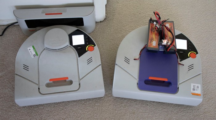
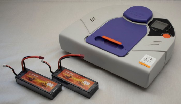
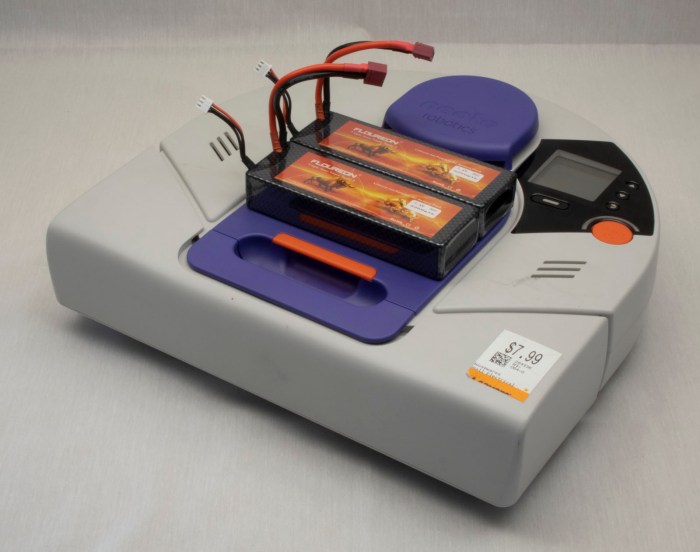
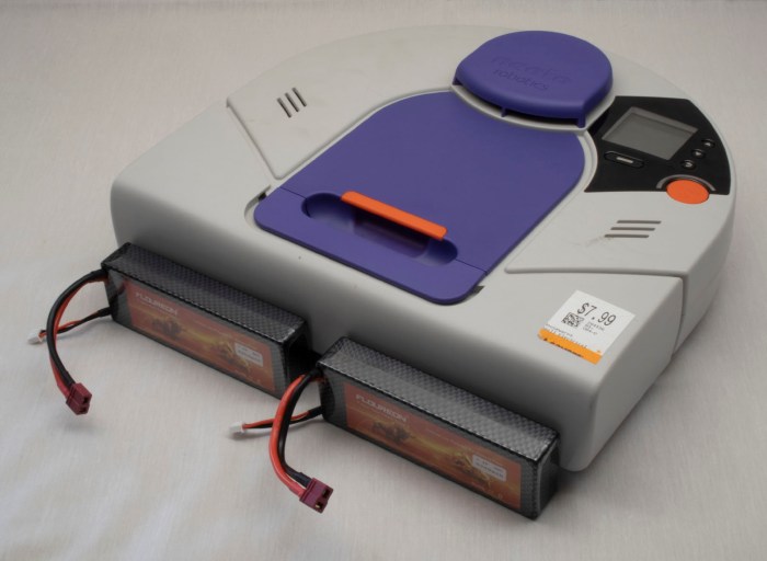
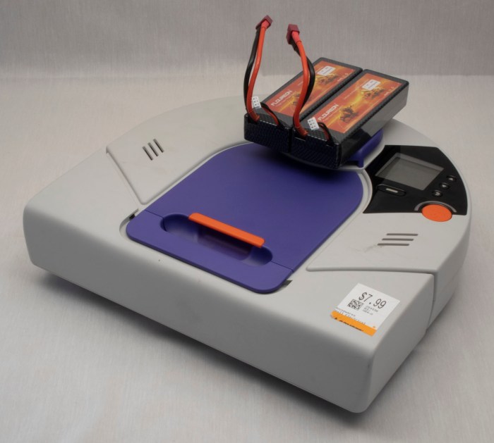
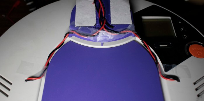
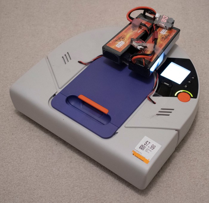
With the experimental batteries in place, the computer boots up and stays up for longer than three seconds. I tried to run a vacuum cycle but that was too much for these batteries to handle, so for now I’ll stick with digital exploration starting with the standard UI to dump revision information on components inside this particular Neato XV-21 robot vacuum.

Neato XV-21 info

After that, it’s time to go exploring through its USB serial port diagnostics!

I went straight to the most interesting component: the laser distance scanner module. First I had to put my vacuum into test mode with testmode on. Followed by setldsrotation on to turn on the motor that sweeps the laser. And finally, fetch a set of laser distance data with getldsscan. This gave me a large set of numbers. According to the legend given in the first line of the response, a distance and intensity number per degree of sweep. Partial excerpt below:

AngleInDegrees,DistInMM,Intensity,ErrorCodeHEX
0,2378,82,0
1,2397,88,0
2,0,88,8021
3,2494,85,0
4,2505,82,0
5,2509,12,0
[…]
355,2289,99,0
356,2303,103,0
357,2303,99,0
358,2315,94,0
359,2367,91,0
ROTATION_SPEED,5.10

Future experimentation will determine what range of distance values are typical, similarly for intensity values. A quick web search failed to find a reference guide for error hex codes, but hopefully there’ll be a small set that I can infer from context. More exploration to come!

In the meantime, I repeated the getldsscan command to verify the values are getting updated. They were – I received a similar but slightly different set of numbers. Hooray! the most important sensor looks like it is functioning.

Next item on the exploration list: querying analog sensor values with getanalogsensors.

SensorName,Value
WallSensorInMM,63,
BatteryVoltageInmV,16120,
LeftDropInMM,60,
RightDropInMM,60,
LeftMagSensor,-2,
RightMagSensor,-3,
UIButtonInmV,3317,
VacuumCurrentInmA,0,
ChargeVoltInmV,132,
BatteryTemp0InC,34,
BatteryTemp1InC,31,
CurrentInmA,622,
SideBrushCurrentInmA,29,
VoltageReferenceInmV,1225,
AccelXInmG,-8,
AccelYInmG,-12,
AccelZInmG,1092,

I see three distance sensors – wall and two drop sensors, one in each front corner. It’s not immediately clear what “Mag” in left and right “MagSensor” referred to. Do they detect magnetic fields? Or are they measuring magnitude of something? Bottom three lines indicate the vacuum sensor suite includes a three-axis accelerometer which can measure in units of thousands of G, implied by a Z value nearly 1000 in this vacuum sitting on the floor. Remainder of the values are related to power management.

The 3-axis accelerometer values above from getanalogsensors partially overlap with results of getaccel. As the name indicates, this one is completely focused on accelerometer readings and includes results of additional calculation in the form of pitch and roll in degrees and a sum of acceleration vector.

Label,Value
PitchInDegrees, -0.64
RollInDegrees, -0.53
XInG,-0.012
YInG,-0.010
ZInG, 1.079
SumInG, 1.079

The list of digital sensor values from getdigitalsensorsis shorter, and for whatever reason, labelled in all capital letters.

Digital Sensor Name, Value
SNSR_DC_JACK_CONNECT,0
SNSR_DUSTBIN_IS_IN,1
SNSR_LEFT_WHEEL_EXTENDED,0
SNSR_RIGHT_WHEEL_EXTENDED,0
LSIDEBIT,0
LFRONTBIT,0
RSIDEBIT,0
RFRONTBIT,0

Here we can see whether the dustbin is installed, whether either or both wheels are at full extension, and it looks like there are four switches associated with the front bumper. The top line shows if a charging plug is connected, but that’s only one of many parameters around power management. Most of the rest are in getcharger.

Label,Value
FuelPercent,88
BatteryOverTemp,0
ChargingActive,0
ChargingEnabled,0
ConfidentOnFuel,0
OnReservedFuel,0
EmptyFuel,0
BatteryFailure,0
ExtPwrPresent,0
ThermistorPresent[0],1
ThermistorPresent[1],1
BattTempCAvg[0],33
BattTempCAvg[1],31
VBattV,16.03
VExtV,0.16
Charger_mAH,0

If I were to create my own control logic for driving my Neato around, the most important parameter here is FuelPercent. I’ll have to be responsible about not draining the battery too far, beyond that I can leave the rest in the capable hands of Neato’s existing battery management system. Speaking of power consumption, the biggest drains are the motors, and I can monitor them all with getmotors.

Parameter,Value
Brush_RPM,0
Brush_mA,0
Vacuum_RPM,0
Vacuum_mA,0
LeftWheel_RPM,0
LeftWheel_Load%,0
LeftWheel_PositionInMM,-1
LeftWheel_Speed,0
RightWheel_RPM,0
RightWheel_Load%,0
RightWheel_PositionInMM,-1
RightWheel_Speed,0
Charger_mAH, 0
SideBrush_mA,28

Not very exciting at the moment, because all motors are at a stop. I imagine these numbers will get more interesting once the robot gets underway.

One final discovery in inputs: when in test mode, the user interface buttons on the top of the robot no longer trigger their usual functions. I could check for status of all five buttons via getbuttons which implies I could use these buttons in my own projects without worrying that I’ll trigger the default vacuum behavior. Cool!

Button Name,Pressed
BTN_SOFT_KEY,0
BTN_SCROLL_UP,0
BTN_START,0
BTN_BACK,0
BTN_SCROLL_DOWN,0

But if I want to actually have my own user interface using those buttons, I would need to also display my own information on the LCD. Which brings us to phase 2 of playing over USB: start sending commands to see if components follow orders.