Wish List For Future Micro Sawppy Control Board

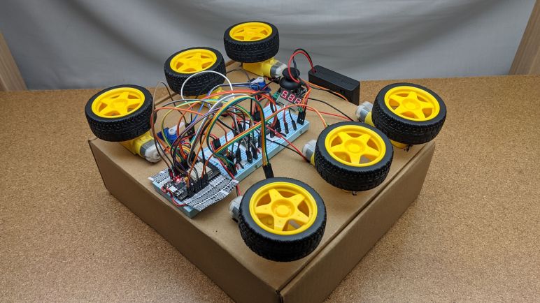
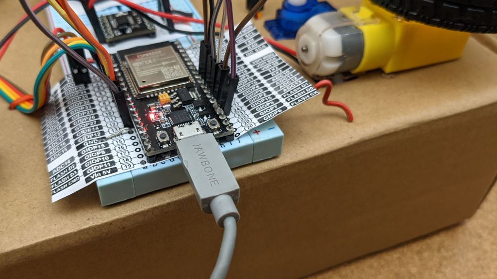
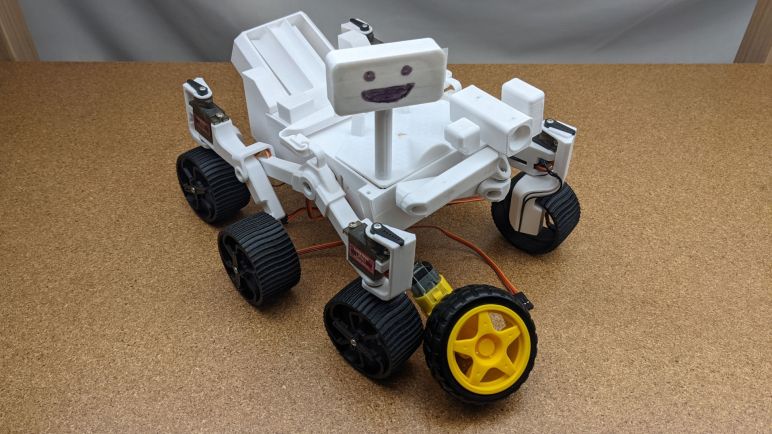
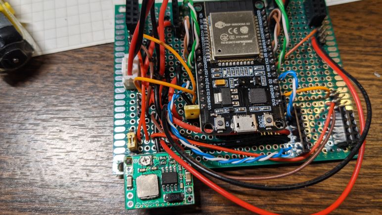
Once I cut an access port for the micro-USB connector on my Micro Sawppy Beta 3 (MSB3) control board, I think I have enough for continue developing my ESP32-based rover software. That’s not to say the control board is in good shape, far from it! It was only the second iteration of my control board design, transition from a breadboard-tested layout to soldered connections. I have many more improvements I want to incorporate for future revisions. All of them are problems on the power delivery side that I want to solve before I work more on the data transmission side.

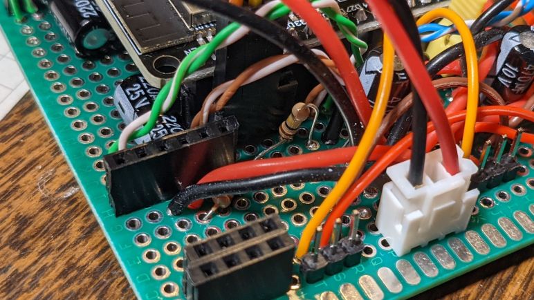
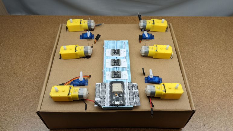
The biggest and most obvious problem that needs solving is making power distribution less chaotic. I used many thick 22AWG wire for this board wired as closely to the battery plug as I could, in the hopes that I will reduce power losses enough to let me run on four AA batteries. Now that I’ve conceded I have to give up on that desire and move to some other power source, there’s less of a motivation for such large wires performing direct delivery. Future versions won’t be as efficient and direct at power distribution, but they wouldn’t need to! I expect they’ll be carrying higher voltage, lower amperage, and tolerate more losses. In exchange, I can make the layout more sane.

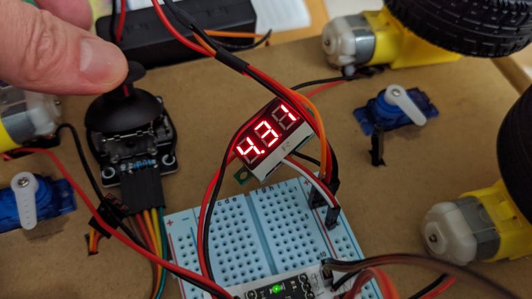
By making the layout more sane, I hope to find room to install a fuse. Right now this control board is running without a fuse, and I think it’s only a matter of time before a wiring accident destroys a component. In fact, I expect that an accidental short will be the reason I retire this board and move on to the next one. With power meter readings indicate steady state of 10W, I have enough data to make a first guess: I think a 2.5A fuse would be appropriate for running batteries anywhere from 7.4V (nominal voltage of two-cell LiPo) to 9V (six AA alkalines.)

Making room for the fuse should also hopefully make room for a voltmeter to the rover. This will let me visually monitor voltage sag as it occurs. Adding another data point to correlate what the ESP32 would sense in software.

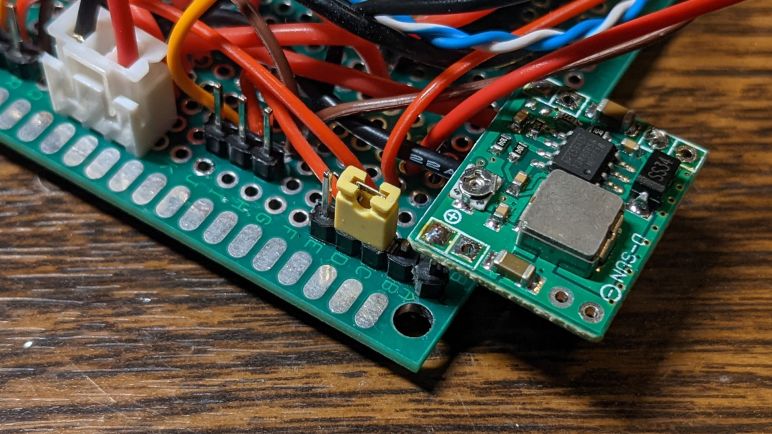
And finally, I think an emergency stop button would be a good safety measure. I don’t think I need it to cut power to the whole rover, just disable the motors should be enough. The DRV8833 DC motor control ICs have an “ENABLE” line and the breakout board I have on hand pulls it up to VCC by default. But it also had provision for me to cut a trace to gain control over that line. The MP1584 buck converter for servo power also has an enable line, although the module I’m using doesn’t seem to have exposed that line. A future control board revision could move to a different breakout module, one which exposes a way for me to control its enable state.

All of those things would be nice to have, but I don’t need them right now to start exploring the first of many ways to control a Sawppy rover wirelessly.

Micro Sawppy Beta 3 USB Access Port

When my little rover Micro Sawppy Beta 3 (MSB3) is running about, its brain built from an ESP32 dev module will be running from battery power. But when I’m updating its software via USB, I have to disconnect the power line to ensure it stays separate from my computer’s USB power line. I originally intended this disconnect to be done by removing a jumper. But after the jumper proved to be too buried to be easily removed, I made a quick hack to change it into a wire. Next step: make the USB port itself easier to access, because it is very much buried in there and hard to access.

I built MSB3’s body before knowing exactly what this circuit board will look like. My original intent is to make the bottom of the tray removable, held only by a few clips. Once those clips were removed I could drop the tray and access the USB port.

Unfortunately, this meant the circuit board is dangling by all the wheel motor and steering servo connections, which meant I’m constantly running the risk of accidentally pulling some wires. Either partially, resulting in an annoying intermittent connection. Or completely, resulting in a loss of functionality or possibly worse with power flowing where it isn’t supposed to. I didn’t like that risk before, and I’m certainly not happy about it now. What I want is a way to access the micro USB port without risking any unplanned wire removal, and that port is sitting behind this unbroken plastic face.

Since this is merely a prototype, there’s no reason why that plastic face must remain unbroken. So I pulled out my drill and started drilling. Starting with a small hole to create a pilot and verify I have the correct location, and gradually working my way towards larger diameter drill bits.

One of the larger drill bits caught and split the case along a printed layer line, but I could still keep things together with my clips so there is no functional problem with the new cracks. It is merely a bit of cosmetic embarrassment, which I can tolerate for the benefit of easy access to my ESP32 dev kit’s micro USB port. There are more things I would like to have in a micro Sawppy rover control board, but this is enough for me to continue working.

Switching From Jumper To Wire For Sawppy ESP32 Power Disconnect

Micro servo angle position inconsistency probably won’t damage a rover, but power problems will. When I decided to use an ESP32 dev module as the brain for my Micro Sawppy rovers, I did not anticipate that power would be a recurring headache in multiple contexts. One context is the fact that my rover has its own power source from a battery, and my computer has its own power source. The problem is that a ESP32 dev module’s micro USB power would tie those two power planes together, and this is not a recipe for success. So I have to be careful to disconnect those two power sources every time I plug in a micro USB cable to update software. Because a computer’s USB port will not have enough power to run a rover, and the rover’s battery must not feed its power into a computer’s USB port.

For my initial breadboard prototype, I took advantage of the solid core wires I used there to build a physical exclusion mechanism. I couldn’t quite carry that feature over to my current perforated prototype board with soldered connections. But I did solder in provision for a jumper to connect ESP32 power to rover battery, and I have to remember to remove this jumper before I plug in a micro USB cable.

To make this jumper more visible and more easily removed, I bought a pack of bright yellow jumper with tall pull tabs. (*) This turned out to be not enough. The tab didn’t really stand above the nest of wires on my prototype board, and it is even harder to access when the prototype board is placed inside my rover’s body. The solution: two jumper wires.

Now I use two lengths of jumper wire, whose top connector rises far above the fray for me to easily access and, almost as importantly, easily seen. I could pull the wires apart for USB uploads, but this leaves a pin dangling about, carrying voltage that might cause problems if it touched anything. So I replaced the single position socket with a three-position socket, the far empty slot holding a connector crimped to no wire. This non-connected position allows me to store the pin when power is disconnected in order to use the micro USB port.


(*) Disclosure: As an Amazon Associate I earn from qualifying purchases.

Micro Servo Angular Position Inconsistency

I got my little rover Micro Sawppy Beta 3 (MSB3) up and running controlled by a wired joystick. This joystick was very simple and affordable but it also had poor proportional response. It was not significantly different from using a digital directional pad, Atari 2600 style. It induced some pretty abrupt movements as I tried to drive MSB3 around, but as a silver lining, it also exposed a problem that went un-noticed in the much gentler MSB1: micro servo angular position isn’t consistent.

To get a better look at this problem, I dug up one of my earlier ESP32 test projects that turned it into a simple servo tester. I plugged all four micro servo motors into the board, so they all receive the same PWM control signal. I then adjusted the signal so they all pointed straight ahead. A little mechanical trim adjustments were needed to get the title image where all wheels were physically aligned.

I then turned the knob on my servo tester and watched all four servos move in not-quite-unison. As we get further and further off center, we can see the steering angles start to vary from one servo to the next even though they are all receiving the same control signal.

I did not see this problem on MSB1 or the cardboard box rover testbed. For MSB1 it might have been related to the fact it used different control electronics, which didn’t fling these servos from one extreme to the other. But a likely contribution is the possibility servos have better consistency within the same batch. All four MSB1 steering servos are from the same batch. The cardboard box rover testbed steering servos are from a different batch than MSB1, but all four are from the same batch.

In contrast, MSB3 has steering servos from different vendors, and different batches. (One of them is even a metal gear MG90S instead of the plastic gear SG90 of the other three.) This came about because I had been testing different servos earlier, but somehow I didn’t notice the angular position discrepancy until now.

As a practical matter, I think this variation is not ideal but within acceptable bounds. This lack of accuracy will merely be noted as another luxury we traded off to lower parts cost of a Micro Sawppy rover. So I’ll leave it and move on as there are lots more tinkering still ahead.

Micro Sawppy Beta 3 Is Moving

Once I soldered wires and noise-reduction capacitors to all six wheel motors of Micro Sawppy Beta 3 (MSB3) I plugged them in to my soldered circuit board. Given that I spent the time to test these parts incrementally as I built them, I was optimistic it would all work. But it was still quite a thrill to have MSB3 scooting along on the floor. All wheels turning and corners steering!

Since it is still running on a simple wired joystick connected via jumper wires only 20cm long, running this rover around is quite a chore. I had to bend low and shuffle to keep up with the rover as it roams the house. If I wanted to build a tethered controller, I need to find a longer cable with at least five wires. If I found one immediately I might have tried it, but I couldn’t find one immediately at hand so I decided that’s really not my priority right now.

Using a small power meter, I monitored power consumption as the little guy ran around. Running full out on a two-cell lithium polymer battery pack, it was drawing just under ten watts dragging the battery from its nominal 7.4 volts down to about 6.5 volts. I had worried that running the wheel motors at 100% duty cycle would damage the motors, as they are officially rated for six volts max, but 6.5V seems to be close enough that nothing immediately melted. Given that steady state is a hair under ten watts, I suspect the initial startup rush likely drew notably over ten watts. This would explain why my 5V 2A USB power bank would balk at this load. (Or the power bank underperformed its specification, or both!)

It was also running a lot faster than I expected from my earlier explorations of TT gearmotor speed range. However, those experiments were performed on four AA batteries so running at full power would have dragged their voltage significantly lower than 6.5V. I think this is another data point in favor of setting up voltage monitoring, so the rover can be smart enough to keep these motors running in their optimal voltage ranges.

So top speed looks to be in good shape, but due to the poor proportional response of these inexpensive joysticks (*) that are practically on/off switches, I couldn’t really run the rover at slow speed. Whether TT gearmotors can be driven slowly enough for rock-crawling duty remains a question mark.

Running MSB3 also exposed a problem I had not seen (or at least not noticed) in earlier Micro Sawppy builds: these micro servos aren’t very consistent in their angular positioning.


(*) Disclosure: As an Amazon Associate I earn from qualifying purchases.

TT Gearbox Motor Wire And Capacitor

Micro Sawppy rover control board has evolved to a perforated circuit board with soldered connection (and a few bonus features like provision for voltage monitoring.) Every time I soldered wiring to support another motor, I tested it on my cardboard box rover testbed solving any problems that were exposed by the testing. Once all six wheels are turning and four corner steering servos moving, I was eager to install it in Micro Sawppy Beta 3 (MSB3) and see it move.

I didn’t want to disassemble MSB3 when I wanted to build a cardboard box rover test bed, so I bought some more TT gearmotors from a different vendor(*) to install in my cardboard box. It was the new lowest bidder of the day, and these motors came with the convenience of wires pre-soldered to the motors. The TT gearmotors on board MSB3(*) didn’t come with wires and I would have to solder them myself before I can drive MSB3 around.

One thing I noticed about the motors with convenient wires is that it didn’t have noise-reduction capacitors. They’re usually absent from simple toys, but anything with electronics usually put capacitors on these motors to avoid glitching the some other part of the circuit. They are certainly considered essential when the device also has any kind of radio communication. The remote control hobby world is where I first learned of their importance, some facilities wouldn’t even let you run your vehicle if it was missing these capacitors, because of the risk it would cause interference with others at the facility and not just your own vehicle. I’m not worried about that in the immediate term. Since the cardboard testbed would always be wire tethered sitting on a tabletop, I didn’t feel compelled to add capacitors. But MSB3 will care about radio noise so I followed Pololu recommendations for adding noise reduction capacitors.

There are three options: a single capacitor across the terminals, or two capacitors from each terminal to the case, or combining both for the best noise reduction. The last time I tried soldering to the case of these little motors, I melted white plastic from the endcap and destroyed the motor. I then tried to remove the plastic part for soldering, but they were only held by bent tabs of metal from the case and they broken off making it impossible to reinstall and again destroying a motor. So in the interest of not destroying motors, I’m going with the simplest option of a single capacitor across the terminals to get MSB3 moving.


(*) Disclosure: As an Amazon Associate I earn from qualifying purchases.

Provision for Micro Sawppy Voltage Monitoring

Recent experience iterating through Micro Sawppy prototypes made it clear I underestimated the task of designing a power supply scheme to fit all of my objectives. My blind spot came from the fact Sawppy V1 was up and running with a very simple scheme for power. I had a two-cell lithium-polymer battery pack, and almost all the components on board were happy to take power directly from that battery and perform their own internal voltage regulation. The only exception was the Raspberry Pi 3 on board, to which I attached a MP1584 buck converter to supply a consistent five volts. It was very little effort to get Sawppy V1 working, so I had the misconception power schemes are easy! They are not.

In order to meet my cost objectives for Micro Sawppy, I switched to different components. These simpler components were far more particular about their power supply, so I had to take on more of the power considerations that were previously a feature built in to more expensive parts. We are now at the point where I think I need to pull the rover’s ESP32 brain into the discussion. The motivation here are the six TT gearboxes and their corresponding motors, officially rated for operation up to 6 volts but can tolerate brief periods above that.

In order to stay below that maximum, the ESP32 can limit its maximum motor control PWM duty cycle sent to the DRV8833 motor control ICs. In an ideal world, if I had a 7.4V power supply, I should be OK as long as I limit PWM duty cycle to no more than (6 / 7.4) = 81%. But this voltage value would change as the battery depletes. When the battery is fully charged at 8.4V, 81% would delivery too much power. And as it approaches depletion of 7V, 81% would be too low to obtain 6V output. What I really want is for the PWM duty cycle to be dynamically adjusted based on battery voltage.

Conveniently, the current pin assignment for ESP32 dev kit still has one input pin open and available for use. So I soldered a pair of resistors to that pin. An 1 MOhm resistor to the battery voltage pane, and a 100 KOhm resistor to ground. This gives me an 11:1 voltage divider which I should be able to read with one of ESP32’s ADC (analog-to-digital conversion) peripherals. This provision will still need corresponding software work before it’ll do anything useful. But if it doesn’t work, it should be pretty easy to clip those resistors off.

The primary objective for voltage monitoring is to dynamically adjust PWM duty cycle in order to maintain rover performance as the battery discharges. Secondary objective is to let the ESP32 send out a low battery alert if the battery is low. Sawppy V1 used an external battery voltage alarm (*) but if I can incorporate that feature into ESP32 software it’ll cut down on parts cost. At the very least, I would like to put the rover into limp mode if the battery voltage drops below a threshold, which would be a feature missing from Sawppy V1.

I expect that battery voltage drop would make the motors unreliable well before it makes the ESP32 unreliable, but as my breadboard test showed, that is still possible. So another potential work item on the to-do list is to enable ESP32 brownout detection capability and recognize when battery voltage is dragged down by rover motors.

Configurable Micro Sawppy Servo Power Supply

My first soldered control board for Micro Sawppy was a huge mess of wires, most of which were related to power distribution. I am confident future revisions will improve, partly from experience and partly from features that I won’t need anymore. One of them is visible in the center of the title picture: a jumper by a MP1584 buck converter voltage regulator. It allowed me to switch between powering the servo with that buck converter and powering the servo directly from battery input power.

Earlier I had determined that four AA alkaline batteries had the right voltage for SG90 micro servos, but that voltage would sag significantly under the load of TT gearmotors driving six wheels. Adding another battery would destroy the servo when the system is unloaded. I knew there were a lot of power losses on my earlier breadboard-based prototype. I thought a soldered board would be a more accurate test. But while it may have made some difference, it was not enough to help Micro Sawppy run reliably on four AA batteries.

If Micro Sawppy is to be powered by alkaline batteries and still avoid using a voltage regulator for servos, I would have to move upscale to higher amperage C or D batteries. I also contemplated the idea of trying one of those large rectangular 6V lantern batteries but they all share the problem of availability. Alkaline C, D, and lantern batteries were once commonplace, but they aren’t very common anymore. I had a few NiMH (nickel-metal hydride) rechargeable batteries in AA form factor, who have the ambition to replace C and D batteries with a few adapter sleeves. I tested them and also found they could not sustain the required amperage under heavy draw.

I could also have multiple four-AA banks in parallel, or have separate power sources: one bank of four AA batteries just for steering servos, driving the remainder of the rover on some other power source. This complexity feels extremely inelegant and I can’t yet think of any reason why this path would be better than conceding that I will need a voltage regulator for steering servos.

So I moved the jumper to the other position, and started using a MP1584 buck converter breakout board set to produce 5.4V. This is between the valid range of 4.8V and 6V, and it is two volts under the nominal 7.4V of 2-cell LiPo I’m using to test this circuit. This two volt margin should be enough for MP1584 buck converter to work.

I used a MP1584 breakout board here because I had leftovers from a multipack (*) I bought for earlier projects, but I’m not confident they are the right device for the job. The datasheet claims it can sustain two amps of output with occasional spikes to maximum of 3 amps. Four SG90 micro servos would usually stay well under that limit, but their power consumption can spike occasionally making capacity planning unpredictable. At the very minimum I should put an electrolytic capacitor to buffer its output, and experimentation will tell me if I need more than that. I might also try to monitor the input voltage level.


(*) Disclosure: As an Amazon Associate I earn from qualifying purchases.

Power Distribution Complicates First Soldered Prototype Circuit

One of my ESP32 dev kit modules was too wide to be breadboard-friendly. But it had reduced pin count, making for a smaller overall footprint on a circuit board so I used it as the centerpiece for a perforated board prototype. This Micro Sawppy control board has the functionality of my breadboard prototype plus a few enhancements.

When I set out to plan my ESP32 control pin assignments, I laid them out roughly in the same physical relationship as they would be on a rover, hoping this would make control wire routing easier. I’m happy to report that this planning paid off, the motor control signal wires were very straightforward to route. For the servo control signals I reused wires from micro servos I negligently destroyed, and for DC motor control signal pairs I pulled solid core wires out of a CAT5E cable which was conveniently in already-twisted together pairs.

What I did not plan out was power distribution, which was something I knew was a challenge yet I had no plan beyond “maybe soldering would help”. Well, the lack of planning really showed in the utter mess of wiring that resulted, as more than half of the wires visible are for power distribution of one context or another. Which wasn’t helped by the fact I used thicker 22AWG wires for power distribution taking up far more space than low-amperage control signal wires. I definitely need to put some thought into power distribution for the next control board revision.

In the middle of the title image is a yellow jumper. When it is in place, the ESP32’s VIN pin is connected to this board’s battery power, letting it run standalone. This jumper must be removed before I upload new software to my ESP32. If not removed and the battery is not connected, the rover will try to run on power from the computer’s USB port which will not work possibly destroying the USB port. Or if the battery is connected, it will send battery voltage into the computer’s USB port which is also a bad thing. Unfortunately this setup doesn’t have the physical exclusion design in my solid-core wire breadboard version. I am scared of forgetting this jumper and want to bring physical exclusion back in a future revision.

I have another jumper on this soldered prototype board, but it serves a completely different purpose.

Another ESP32 Dev Kit Layout

After destroying a few SG90 micro servos and admitting I should have known better, I think the breadboard prototype circuit board has fulfilled its mission and it’s time to move on. My next iteration of Micro Sawppy rover control circuit will be a perforated prototype board with soldered connections. Having soldered connections will help give me more reliable connections and also reduce loss of electrical power from thin wires, which may or may not help with my power supply problems.

For my breadboard prototype I chose one of the ESP32 development modules that were narrow enough to fit well on a breadboard, leaving room on either side for jumper wires. (Left module on title image.) The narrow width meant there was no room left for pin labels, but I found a paper template that I could use to help with pin identification.

Now that I am building a soldered circuit, I no longer need to use the narrow module. So I pulled out a different development module I had bought(*) for exploring ESP32 development. (Right module on title image.) This one is wider and longer, giving us several advantages including screw mounting holes in each corner. Even thought it was longer, we have fewer pins to worry about, because this design didn’t bother to bring out the six pins corresponding to this ESP32 module’s built-in flash memory. We couldn’t use those pins in our design anyway so it was no huge loss. Conveniently, those flash memory pins were divided three on each side, so their removal still left the layout symmetric. A fourth pin was dropped from each side. On one side, an extraneous ground pin and on the other, pin zero was omitted. This is technically an available I/O pin but using it is tricky. It is a part of ESP32 startup process, the pin pulled to ground by the BOOT button. I had considered it a “pin of last resort” and avoided allocating it in my allocation scheme, so its subtraction from this module was fine for my use. All of the remaining IO pins are brought out on this module, and it even maintained the same relative ordering of those pins making it familiar to use. Helped by the fact that its more generous width also allowed onboard labels on these pins, eliminating the need for a paper template.

On board the module, I saw a very similar set of components. Two buttons “EN” and “BOOT” surround the micro USB port. There is a chip to handle USB serial translation, and an AMS1117-3.3 handles voltage regulation. I think I see a second LED which was absent from Espressif’s reference design but present in a few other dev kits I’ve used. But I also see one oddball: it appears a capacitor next to the EN button is at an unusual angle. When I see a surface mount component at a non-orthogonal angle, my first thought is a pick-and-place or soldering error. But this capacitor seems to be bridging two real pads and not dangling off into space, so it’s probably not an error. It might be some sort of a hack to address some problem discovered after the rest of the board was laid out, I’m not sure. As long as the module works I guess it really doesn’t matter. As a test I flashed my ESP32 test program and saw the second LED start blinking. Good enough to get to work.


(*) Disclosure: As an Amazon Associate I earn from qualifying purchases.

Aftermath of Exceeding SG90 Micro Servo Six Volt Maximum

I wanted Micro Sawppy rover to be a beginner-friendly design, which meant avoiding the hassles of working directly with lithium chemistry rechargeable battery cells. I investigated a few options, starting with four AA alkaline cells in series, but none were able to sustain power in the five-to-six volt range I sought. Sagging under four volts in the worst case. I thought the next obvious step in the investigation would be to add an AA battery for five AA in series. This was a mistake.

I had examined micro servo electronics earlier, and I found that operating at their quoted 4.8V nominal voltage was actually unreliable. I really needed to feed them at least five to six volts. In my experiment earlier, I found my little servo could operate at 7.4V (nominal voltage of two-cell lithium cells) but would not tolerate 8.4V (fully charged two-cell lithium cells.)

Based on this knowledge, I thought five AA cells would be fine, as they would have a maximum voltage of 7.2V. However, I had forgotten that my high voltage experiment were on a MG90S servo, not a SG90. And with the variation of electronics across all those servos I had taken apart, results for one wouldn’t be reliable for another anyway. I added the fifth AA cell and, immediately upon applying power, I smelled the telltale scent of unhappy electronics.

Uh-oh.

I disconnected power and examined my two servos that no longer responded to commands. They were warm to the touch and have a distinct bulge of melted plastic on their enclosure. The title image showed one of these damaged servos (right) next to an unused servo from the same batch (left) both angled to highlight surface features. I opened up the bulged case and saw the servo control chip has melted the top of its chip packaging. And not only that, it melted a rectangle into the blue plastic enclosure which was directly under the bubble.

It is obvious that I should not feed these micro servos any more than 6V, the historical standard for remote control hobby electronics. Derived from the voltage for four fully charged nickel-cadmium (NiCad) battery cells in series. Which meant if I wanted to increase power level for the rest of Micro Sawppy, I would need a regulator to ensure micro servos input voltage do not exceed 6V. This would mean extra components and complexity, but at the moment I see no way around it.

There is a slim chance the problem isn’t as dire as it appears at the moment. My cardboard box rover uses a breadboard and jumper wires to create its circuitry, and this system doesn’t have very high current-carrying capacity. It is possible that I’m losing a lot of power to resistance of thin wires, a problem that has occasionally plagued past projects. Now that the breadboard and jumper wires have done their job of exposing problems in a prototype, I should move on to a circuit board with soldered connections. Trying four AA batteries on that circuit would be a better representation of the little rover’s power situation, as well as freeing me from physical constraints of breadboard dimensions.

Initial Thoughts on Micro Sawppy Rover Battery Power

Wiring up all the motorized components on my cardboard rover testbed exposed a few minor problems that were easily fixed, but exposed battery power as a headache I’ll have to deal with. Sawppy Rover V1 and Micro Sawppy Beta 1 both used lithium-polymer battery packs from the world of remote-control hobbies. They are lightweight and powerful, but they are also sensitive to mechanical damage and occasionally react very badly to abuse. I have ambition to make Micro Sawppy a small beginner-friendly rover design, so I didn’t want people to be intimidated by all the dire warning surrounding proper LiPo care and feeding. Also, while lithium battery costs have dramatically dropped over the past years, they are still relatively expensive and I wanted to keep Micro Sawppy affordable.

Which was why for my cardboard rover testbed, I started with a pack of four AA alkaline batteries. Alkaline AAs are common, inexpensive, and tolerant of abuse. Four of them in series deliver a maximum of six volts, aligning with the maximum rated voltage for TT gearmotors and SG90 servos I used on Micro Sawppy. Which is why a four-pack of AA is a very popular way to power small robot kits using those components. The difference is that they usually only have a pair of TT gearmotors, whereas Micro Sawppy has six. They also have fewer than four SG90 micro servos like those handling corner steering here. With all of these components, my cardboard rover has proved to be too much work for four AAs. Dragging its output voltage below four volts and triggering a brownout reset of the ESP32 brain.

My next idea on a way out of this predicament is to use a commodity USB power bank. They produce nominal 5V for charging USB devices. They are usually built around lithium batteries, but they are a self-enclosed device with a durable shell and protective circuitry. Making them a beginner-friendly safe way to incorporate lithium battery power. Officially USB1 only allowed devices to draw half an amp at five volts, which is not nearly enough for a rover. But newer USB power banks advertise higher power levels, some of them communicate using a secret handshake to indicate this capability. I had a few different power banks on hand, advertising maximum output of up to 2A. Unfortunately none of those were able to sustain power delivery for my cardboard box rover, either.

All of these power sources advertised power ranging from 5V but none of them could sustain that under the load of Micro Sawppy motors. I then returned to the idea of using alkaline AA batteries and thought… what if I added one battery, for five AA batteries in series? The answer is: some micro servos get very unhappy and quit.

Cardboard Rover Testbed Wheels Turning And Steering

Once I figured out how to handle power for ESP32 on my cardboard box rover testbed, I started connecting the rest of the components. Since I had motor control PWM code ready to go, I started by connecting the DRV8833 breakout boards one by one to the power rail. Which for this experiment was a battery holder for four AA alkaline batteries that had a power switch built in. (*)

I wanted to start with 4 AAs because alkaline batteries are commonplace and more importantly, tolerant of abuse compared to sensitive lithium ion batteries. I’m not squeamish about working with lithium battery packs personally, but I am squeamish about using them on a rover design I want to advertise as beginner-friendly. Four fresh AA batteries in series would deliver 6V, which is coincidentally the maximum spec voltage for both SG90 micro servos and TT gearmotors. Thus a four-pack of AA is a common power supply for little robot kits using similar components.

Here I am thankful for the LED indicating power supply, which was not part of the DRV8833 data sheet but added as a bonus on the particular breakout boards I had bought. Each module was powered-on to verify the power LED illuminated, then I turned it off to install one wheel. After I turned it back on to verify one wheel is working correctly, I would turn it off and connect the other wheel for verification. Testing parts one step at a time ensured that whenever something went wrong (and they did) I would know where to start looking.

As I connected more motors, I noticed that the DRV8833 power LED would visibly dim when the wheels start turning. To monitor voltage, I wired in a compact voltmeter(*) originally purchased to monitor battery voltage on Sawppy V1. I saw the voltage would sag from nearly 6V to just under 5V. More of a drop than I had expected, but with all six wheel drive motors in place I thought I was in good shape. It turned out I severely underestimated the peak power draw for four corner steering SG90 micro servos. When those little servos are trying to reach a new position ASAP, they seemed to draw more than the TT gear boxes despite their physically smaller motors. During regular operation my four-pack of AA would struggle to stay above 4V, and if the steering servo encounters any obstruction, it would drop below 4V causing the ESP32 to brown out and reset. This is obviously Not Good and I will need to put more thinking into power supply.


(*) Disclosure: As an Amazon Associate I earn from qualifying purchases.

Cardboard Box Rover Testbed ESP32 Power Supply

Power distribution is a concern in any electronics project, but a breadboard ESP32 circuit mounted on a cardboard box rover stand-in has an additional twist: USB. When a USB cable is plugged in to my ESP32 dev kit to upload new firmware and serial monitoring, it is also connected to the computer’s +5V power rail. But when my rover is out and about on its own, that USB connection will be absent and ESP32 will have to draw power from the onboard battery.

I initially thought I would have to install a 5-volt regulator on my rover to power the ESP32, much as how I had been using MP1584 buck converters to power Raspberry Pi 3 for earlier projects such as Sawppy V1. Then I remembered the ESP32 is a 3.3V part so there must already be a voltage regulator of some sort on the dev kit. Looking on the board and confirmed on the schematic, there is a AMS1117-3.3 LDO (low drop-out) regulator on duty. These regulators are happy to accept voltage up to 15V and down to as low as 1.3V over the output voltage, which in this case is 3.3 + 1.3 = 4.6V.

Looking over the schematic that HiLetgo bundled with this ESP32 dev kit, I see the onboard USB serial interface chip also runs on the 3.3V regulator output. Another thing this “Vin” pin is connected directly to is the power LED, which has a 1k current-limiting resistor so it can tolerate higher than 5V of input.

So that leaves the USB cable’s +5V line. If I have battery power voltage on that VIN pin, I don’t want that voltage to feed into my computer’s USB port. I need to make sure this ESP32 can connect to USB or battery power but never both at the same time. My solution is to use a length of solid-core wire to bridge battery power input to the Vin pin, and shaping the wire so it blocks the USB port. This way, I can’t connect this wire while the USB plug is in use.

In order to use USB power, I have to disconnect the VIN wire and swing it out of the way like a gate. In order to make sure that battery voltage wire doesn’t touch anything inconvenient while it is out of the way, I stabbed the exposed solid core wire into cardboard to tie up that literal loose end.

None of the remaining components on the rover testbed will need to receive software updates over USB, so this is the only place where I had to worry about switching between two power sources. Everything else will be wired directly to battery power.

Cardboard Box Rover Testbed Breadboard

Writing down ESP32 pin assignments in a spreadsheet is a good to plan things out ahead of time, but it isn’t a robot until wires are connected and circuits completed. I’ll test the plan on my cardboard box rover testbed. When I cut out the holes for all those motors and servos, I left a space open in the middle for circuitry. Since this is a testbed to prove out a plan, I want the flexibility to easily test things incrementally as I build things piece by piece. It would also be nice to easily fix problems I will undoubtedly discover during testing. Both of these desires pointed to a breadboard and jumper wire instead of a more permanent soldered solution.

In my collection of ESP32 development kits, there is a very important differentiation for this task: some of these modules are 0.1″ wider than the others. This difference is critically important for a breadboard prototype: the narrower modules leave one breadboard hole exposed on either side for jumper wiring, in contrast the wider module would completely block all holes on one side. To use wider modules on a breadboard, all the wires have to run underneath the module making them much less experimentation-friendly than their thinner counterparts. For this particular project I’m using an ESP32 dev module I purchased from this Amazon link (*) but there’s no guarantee the vendor wouldn’t change things up in the future.

One problem with the narrower module is that its compact layout left no space for labels on the visible side of the board. Rather than laboriously looking up charts and counting pins every time a wire connection is to be made, some clever people have designed paper templates to help with the task. I found one that matched my ESP32 dev kit at this link. Checking against my dev kit’s schematic, I see it is functionally correct though there is an inconsequential cosmetic typo of GIOP instead of GPIO. Printing out the PDF at 100% scale will match size with the real thing, which I then put between the breadboard and my ESP32 as I pushed the ESP32 dev kit in to the breadboard. Metal pins have no problem punching through that paper, and the paper is not conductive enough to cause problems with the circuit.

Having a pinout reference immediately available cuts down on frustration and mistakes, and I liked the idea so much I wanted them for my DRV8833 breakout boards as well. Because those breakout boards also had visible pin labels on their downward-facing side of the board. I didn’t have the skill to draw up a nice template using graphics design software, but using a sheet of paper I could create a hand-written reference.


(*) Disclosure: As an Amazon Associate I earn from qualifying purchases.

Assigning Pins for Sawppy Rover ESP32

As part of exploring MCPWM duty cycles, I had to make decisions on ESP32 pin assignments. This is how my ESP32 DevKit will communicate with my DC motor driver and steering servos. Three DRV8833 motor driver IC breakout boards for Micro Sawppy rover’s six TT gear motors driving wheels, plus four corner steering servos. Together they require sixteen PWM pins which is within an ESP32’s capability.

I’m very thankful for this compilation of ESP32 pinout from Random Nerd Tutorials, which served as a starting point and immediately crossed off many off-limit pins like those tied to ESP32 flash memory access. I also eliminated the primary serial transmit & receive pins from consideration as I wanted to keep them available for serial monitoring.

The next pins I wanted to keep clear were the two hardware I2C pins. I want to be build a baseline ESP32-controlled rover with as few external support chips as possible. But if I can leave the I2C pins free, that leaves the door open for add-ons and expansions. Additional PWM pins can be added with something like the popular PCA9685 chip. (*) And additional digital input/output pins can be added via PCF8574 (*) or similar chips. In fact, if I get to a point where I desire specific ESP32 peripherals (capacitive touch?) I can offload all wheel driving and steering duties to an external PWM chip.

I wanted to leave hardware SPI pins open for the same reason, but SPI was a luxury I could not afford. That would mean leaving four more pins unused and that’s more than I can spare for my baseline design. If SPI becomes important, I’ll need to offload some wheel control to external PWM chips. Another luxury I had to leave behind are the JTAG debug pins, which also demanded four pins I could not spare unless I offload PWM to external components.

But even though I could use those JTAG pins for general output, some care had to be taken because there will be some spurious signals on those pins. Upon power-up, before my code can run to configure those pins for PWM output, these pins will have signals corresponding to JTAG or other system use. In practice I expect this to mean my rover will twitch a little bit at startup, so I assigned those pins to steering servo signal duty. I rather that my rover steering servo twitch on powerup instead of a drive wheel. I don’t want the rover to drive itself forward or back uncontrolled, no matter how briefly.

After all of the above concerns are factored in, the final one is the physical relationship of pins. I wanted to keep related pins close together, such as the A and B lines for motor control. This is a little tricky to do on the Random Nerd Tutorials chart, because it is sorted by GPIO number instead of their physical position. I used Excel to create a chart that maps the physical location of those pins. Then I assigned their use so they roughly correlate to their positions on the rover, with the DevKit USB port pointing towards back. In reality the wiring won’t be that straightforward because the motor control lines will have to go through a DRV8833 first, but it might help me during debugging.

The assignments are listed on the outer-most columns of the chart. The first letter is one of (F)ront, (M)id, or (B)ack. The second letter is (L)eft or (R)ight. The third letter is (A) and (B) for DRV8833 motor control, or (S) for steering servo. This particular set of assignments leaves the I2C SDA & SCL pins free. Unencumbered GPIO23 is left free and clear for anything. The four input-only pins 34, 35, 36, and 39 are still available. And as a last resort, we still have the restricted-use GPIO0 pin. With this plan for pin assignments in hand, I proceed to turn the plan into reality.


(*) Disclosure: As an Amazon Associate I earn from qualifying purchases.

Interactive MCPWM Duty Cycle Explorer

I started exploring TT gearmotor response to different duty cycles by editing MCPWM parameters in source code, compile with those new parameters, and uploading the results to my ESP32 motor control test bench board. It took only three cycles of this process before it was painfully clear I needed a better way. So I copied an excerpt (the joystick and MCPWM portions) of my ESP32 Sawppy control software out to a separate test program in order to interactively explore TT gearbox behavior under different duty cycles.

This test program only dynamically varies the duty cycle, not the PWM frequency. I’m running my program at a PWM frequency of 20 kHz. There may be an annoying whine audible to dogs and newborns, but it’s comfortably above my not-spring-chicken range of hearing. A brief test established that these TT gear motors behave differently at lower PWM frequencies. The most consequential effect is that I could turn them at a lower minimum speed. Still not rock-climbing slow, but there’s definitely an effect. I don’t have enough electrical engineering background to understand why I have more torque with lower PWM frequency, so I’ll have to come back to this topic later to find an explanation for my observation. In the meantime I’m insistent on 20 kHz PWM because I don’t like to hear the whining.

In my test program I didn’t have a real need for analog control, so the joystick was effectively turned into a direction pad. Pushing one direction increments duty cycle, pushing the opposite decrements it. The orthogonal axis adjusts the increment rate, so I can adjust in duty cycle increments of 10%, 1%, and 0.1%. In order to test startup power, I could press down on the stick to trigger its associated button. This button toggles motor power on and off. This program is only useful when connected to serial monitor because the increment rate and the current duty cycle are displayed via text sent over serial link. I plan to use this tool again once Micro Sawppy is rolling on its own wheels, in order to update speed-to-duty cycle mapping to reflect realistic loads on the wheels rather than unloaded spinning in the air.

In theory it should be possible to have this tool as a part of Sawppy ESP32 control code instead of a separate project. I would have to set up some sort of conditional compilation mechanism so I could toggle whether to compile standard Sawppy control or this duty cycle explorer. However, I don’t see any particular motivation to perform this work today so until I see a benefit, I’ll leave that integration task on the to-do list for the future. With some working PWM duty cycles in hand I can start putting them to work with ESP32 GPIO pin assignments.


[ This test program is publicly available on GitHub. ]

Exploring TT Gear Motor Speed Range

I wrote my ESP32 Sawppy rover chassis Ackermann geometry code to output calculated wheel speeds and steering angles in an implementation-neutral (but not similar to ros_control) way. Wheel speeds were specified in meters per second of desired ground travel speed, so the next step is to translate that into DRV8833 MCPWM control signals driving TT gear motors.

This conversion will be some kind of mapping from desired wheel travel velocity to PWM duty cycle. Without closed-loop control, I knew the mapping would not be accurate, but maybe it’ll close enough to be acceptable at this price point. I’m not sure how much of a load will be borne by each rover wheel yet, so the first draft of this mapping will work with the wheels spinning freely in air without load. Since a single DRV8833 can drive two motors, I drove a pair of TT gearmotors with the same electrical PWM parameters. I was not surprised to find that they had slightly different speeds. It’s not even a consistent ratio: one motor was faster at full power, while the other was faster at low power. Looks like the error bars on my mapping are getting longer and longer with each discovery!

For the sake of getting some numbers as a starting point, I estimated unloaded wheel travel speed at 6V to be approximately 0.6 m/sec. With this, I’m cautiously optimistic that Micro Sawppy rovers running on TT gear motors will be able to keep up with Sawppy V1 with its much larger diameter wheels. However, they won’t have the same performance at the low end. Unloaded, these TT gearmotors could turn as low as 15cm/sec, but just barely. Any slower than that and the motor couldn’t overcome internal gearbox friction. Such behavior implies these little rovers wouldn’t be much good for low speed rock climbing. This initial experiment found that TT gearmotors maximum speed isn’t very fast, and their minimum speed isn’t very slow. But it’s still an open question whether they are “good enough” for the sake of making an affordable micro Sawppy rover. I already know I need to revisit this speed range exploration once the rover is running on its wheels, so I wrote a tool to make that process less painful.

Abandoning ros_control Analogy for Micro Sawppy

Every time I revisit the task of writing Sawppy rover control code, I’m optimistic that I’m one step closer to not having to rewrite from scratch again. This time around, I’m following conventions set by decade-long development of ROS (Robot Operating System) but writing in low-level C code that should run on anything from embedded microcontrollers on up. This approach adds a few challenges but I hope it’ll be more adaptable to other platforms (both software and hardware) in the future.

On the hardware front, many robot chassis that advertise ROS compatibility uses the velocity command (cmd_vel) topic as their interface layer to ROS autonomy logic nodes. Hardware-specific code listens to messages sent to that topic, and handle translating desired velocity into physical movement. I will follow that precedent but I also had the ambition to go one step further with some inspiration from ros_control. The key word is “had”, past tense.

As I understand it, ros_control original motivation was to interface with components that one would find on a robot arm, creating a generic interface for motors and actuators. This allows for generalized operation with ROS nodes like the MoveIt framework for motion planning, and it is also the interface layer for switching between real and virtual robots for the Ignition Gazebo simulator. And since it’s generic, it’s perfectly valid to try to apply those concept to motors and actuators for chassis locomotion.

I like the concept, but I got lost when wading into documentation. When I dug into one of the actual interfaces like JointPositionController, I saw only a setCommand() that sends a single double-precision floating point value. This is clearly only part of the picture. What is the context that number? For actuators like RC servo it would be a rotation, but for a linear actuator it would be a distance. How would I communicate that information, along with other context like whether that rotation/distance is along X, Y, or Z axis?

Furthermore, the interface assumes closed-loop control on every actuator, since the interface has getPosition() to query status and setGains() to adjust PID coefficients. I wouldn’t be able to offer any of that on a micro Sawppy rover. RC servos do perform closed-loop control, but the loop is closed within the servo and the robot has no visibility to actual position or adjust PID coefficients. And without an encoder wheel, TT gear motors have no closed loop control at all. Some ROS tutorials (like this one) asserted there’s no point to ros_control on low-end robots and I now understand their point.

Since I don’t understand concepts of ros_control yet, I’ve chosen to postpone that idea for ESP32 Micro Sawppy software. The worst downside is that I might go down a path that will require another rewrite in the future. But hey, I’ve done it before and I can do it again. To mitigate this risk, I’ll still communicate my rover actuator commands using unit conventions as described by REP103. So I’ll communicate steering angles using radians instead of RC servo commands, which should be friendlier to conversion to different actuators in the future. Similarly, wheel speed will be communicated in meters per second rather than motor power level, again in the hopes it’ll be generic enough for other actuators in the future. Today I’ll pack them into a single message for short term ease and deal with that problem later. I have a more immediate problem: I found the TT gearboxes have a narrower range of speed than I originally thought.

Revisiting Sawppy Geometry Jupyter Notebook

My decision to follow ROS conventions for my Micro Sawppy rover control software also meant taking on some of the challenges of adapting manual control conventions to an automation-centric world. I remain optimistic that this short term pain will prove worthwhile long term, but it’ll be some time before I know for sure.

I chose an ESP32 as my rover brain, thanks to its feature set being a good match for my ambition to design a low-cost entry-level rover. The cost-cutting decision to move hardware from Raspberry Pi to ESP32 has a big impact on the software environment. From Python running on a general purpose Linux-based operating system to C running on a bare-bones FreeRTOS environment optimized for embedded systems. While I’ve written a C version for Sawppy’s alternate Arduino control scheme, I couldn’t port my old code straight across due to my new ROS-centric focus.

This is far from the first attempt at a ROS-friendly Sawppy rover code base. I tried to do it once myself before aborting that effort due to unneeded duplication. I looked at Rhys Mainwaring’s rover software stack for ROS Melodic to see if I could adapt it to Micro Sawppy’s ESP32. Logic-wise, it follows all the ROS conventions I wanted to follow, but it also used all the ROS software frameworks I won’t have on an ESP32. I also wanted more abstraction between rover chassis math and actuator code. In ROS this is the job of ros_control which Rhys plans to adopt, but that is part of the ROS infrastructure I won’t have on bare ESP32 FreeRTOS.

So I went back to something I created as part of my aborted effort: a Jupyter notebook for working through my rover math. Jupyter has since evolved into JupyterLab but it didn’t seem to have any problem opening up my old notebook. Thanks to all the markdown documentation I had written alongside my Python code in the Jupyter notebook, I could quickly get back up to speed on my thinking on the project. Reviewing my code months later, I even found and fixed a bug that slipped through earlier! I’m not sure this is the most elegant fix, my Python code is not very “Pythonic” because I still think like a C programmer. It is technically a bug, but today it is a feature because I’m porting it to C that will compile for ESP32. My plan was to build a FreeRTOS task that takes a desired rover chassis movement command similar to a ROS cmd_vel message, and outputs data similar to a ros_control message… but then my plan changed.