Old Industrial XY Stage Moves Again On Arduino AccelStepper

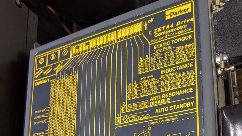
A decades-old piece of industrial equipment has failed and been retired, but its motion control table was still good and salvaged for a potential future project. It is a far cry from the kind of motion control equipment I see on a hobbyist 3D printer. Much more rigid chassis, more precise linear guides, finer pitch thread, far beefier motor, under the command of a much more capable control box. One example: the A4988 stepper motor popular in 3D printers features the capability to generate up to 16 microsteps in between whole steps of a stepper motor. In contrast this Parker ZETA4 unit features up to 255 microsteps.

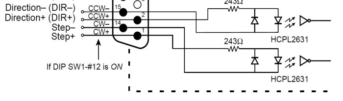
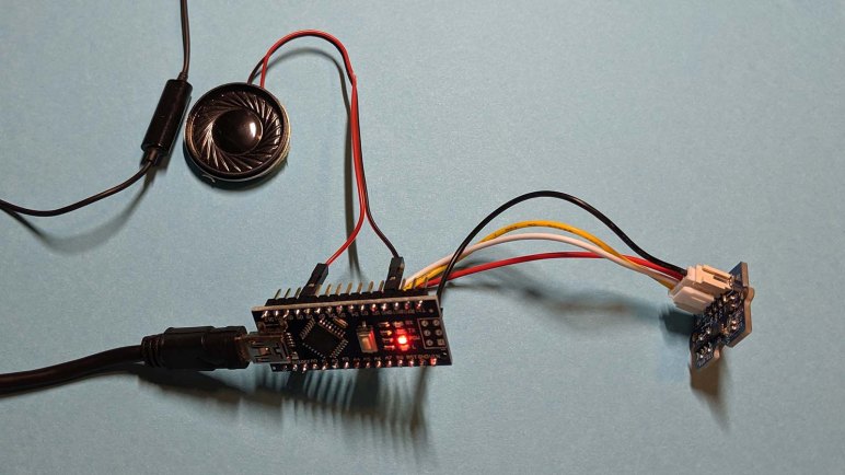
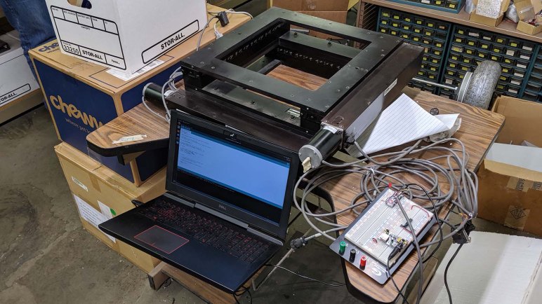
Pulling from the electronic hobbyist world, I set up my Arduino to run the AccelStepper library generating stepper motor direction and pulse signals. It was connected to one axis of the XY stage for the first test. It was exciting when the motor started turning, but it was very very loud! I doubted it was supposed to sound like that. A bit of examination found two problems: the ZETA4 was configured to take whole steps — no microsteps — which is always noisy. And I amplified this mistake by accidentally choosing a speed that caused a resonance.

Once the ZETA4 was configured to its default of 125 microsteps, things were much quieter and smoother. It also slowed down significantly, because each pulse on the step pin moved 1/125 as far as it did before. (And a full revolution of the motor was only 200 steps.) The obvious answer was to increase frequency of those pulses, but I seemed to top out at around 5,000 pulses per second. This surprised me: The ATmega328 chip on board an Arduino is running at 8MHz. I would have expected it to easily generate pulses faster than 5 kHz. Time to put this guy under the oscilloscope and see what we see.

New Project: XY Stage

The next project seizes upon the opportunity to work with a piece of industrial equipment whose price tag is far too high for me to justify spending on a hobbyist project. It is a combination of two linear stages bolted together at right angles to each other, allowing precise motion control along two axis. A configuration like this usually ends up handling the X and Y axis, so I’m going to call this the XY Stage project.

It formerly controlled the movement in some sort of inspection machine. The machine is decades old and, when the ancient DOS PC running everything died, the machine was retired rather than repaired. The old computer, associated software, and camera system were not interesting: the world has long since moved beyond their capabilities. The XY stage, however, is still perfectly functional and was salvaged for potential use in a project. Its capabilities has not been entirely outdistanced by its modern counterparts.

The control logic entry point for the system are these Parker ZETA4 Drive Compumotor modules. The design has long since been retired. However, machines built on them are still running and there’s still a market for those modules. Available new for around two thousand US dollars, they are also available used for several hundred dollars. On the side of this module is an imposing looking chart detailing all the ways it can be configured. But if we can temporarily set them aside, we see the method of control are two pins: one for direction, and another for step.

ZETA4 step dir

That makes it a lot less intimidating! Control protocol for this big box is basically the same as the A4988 stepper motor driver boards popular in hobbyist 3D printers. From a system architecture perspective, this is “merely” a larger, more expensive, more durable, more precise, and more powerful cousin to the little fingernail-sized circuit boards in my 3D printer control box. It is completely within our capabilities to command such a device.

I don’t know what we might be able to do with a XY stage, but I know it is too good to be gathering dust. I want to see if I can get it to do my bidding, and once I have a better understanding of its strengths and weaknesses, I’m confident a suitable project will arise.

A Day At CRASH Space LA

Visiting CRASH Space LA has been on my to-do list ever since I was introduced to Barb and Jay at Maker Faire 2018. We’ve seen each other at numerous events since then and it was pretty ridiculous that I see them more often in San Mateo than our home town. The problem is that they are on the far side of the basin. Going to Culver City in the context of infamous LA traffic meant a visit is not “I’ll just stop by.” It is a day trip kind of expedition! Finally Emily and I visited during their “Mega Take Apart & Swap Meet” day this month.

I brought some things but Emily brought more, and they were more interesting. She tore into some sort of retired dental surgery tool with components indicating high voltage operation. We’re not sure why a dentist would need high voltage in our mouths, and we didn’t much care. (Or chose not to think about it.) What’s inside is far more interesting.

I dug into another box Emily had brought. Some sort of power supply that had all appearance of being an one-off homebuilt project.

After the take-apart event Emily went off to visit friends living in that part of town. I stuck around CRASH Space for their Video Dim Sum event where I learned there are a lot of very odd things available on YouTube. I expected this, so it was a 100% success on that front. However my taste rarely aligned with the people who submitted videos so my overall entertainment-to-time ratio was pretty poor. I did learn some interesting things that I would not have otherwise, so it was still a fun thing to try at least once.

Out of all the videos that were shown, just one of them were memorable and compelling enough for me to go find and rewatch. Here it is, my personal winner of Video Dim Sum:

Raspberry Pi Web Kiosk Boots Faster On Raspbian Than Ubuntu Core

My adventures into the lightweight Ubuntu Core operating system was motivated by a 14-year old laptop with Intel CPU. By multiple measures on the specification sheet, it is roughly equivalent to a modern Raspberry Pi. (~1 GHz processor, ~1GB RAM, ~30GB storage, etc.) As a test drive, I had tried setting it up as a web kiosk and failed due to incomplete graphics driver support. (Though I did get it working on a modern laptop.)

Which leads to the next question: how well does Ubuntu Core perform on a Raspberry Pi performing the exact same web kiosk task? And how does that compare to doing the same thing on Raspbian OS? They’re both variants of Linux trimmed down for less powerful hardware. Raspbian is packed with features to help computing beginners get started, and Ubuntu Core has almost no features at all to offer a clean baseline.

My workbench is not a comparison test lab so I didn’t have many copies of identical hardware for a rigorous comparison. Two monitors were close but not quite identical in resolution. (1920×1080 for the LG, 1920×1200 for the Dell.) The two Raspberry Pi should be identical, as should the microSD cards, but they’re not powered by identical power supplies. To establish a baseline, I set them both up for Raspberry Pi web kiosk using my top search hit for “Raspberry Pi Web Kiosk”. Then launched them side-by-side a few times to see how close their performance were from power-up to rendering a web page. (For this test, the Hackaday.com site.) This took approximately 40-45 seconds, sometimes one is faster and sometimes the other is faster. For some runs, the two systems were within one second of each other, sometimes they were almost 5 seconds apart. Establishing the fact this comparison method has a measuring error of several seconds.

With an error margin established, I removed one of their microSD cards and installed Ubuntu Core for Raspberry Pi 3 on it. Once initial configuration were complete, I installed snaps for the web kiosk tutorial I followed earlier for the Dell laptops. I was very curious how fast a stripped-down version of Ubuntu would perform here.

The answer: not very, at least not in the boot-up process. From power-up to displaying the web page, Ubuntu Core web kiosk took almost 80 seconds. Double the time necessary for Raspbian, and that was even with a full install of Raspbian Buster with zero optimizations. There are many tutorials online for building a Raspbian-based web kiosk with stripped-down list of components, or even starting with the slimmer Raspbian Buster Lite operating system which would only get faster.

There may be many good reasons to use Ubuntu Core on a Raspberry Pi (smaller attack surface, designed with security in mind, etc.) but this little comparison indicates boot-up speed is not one of them.

Ubuntu Core 18 Web Kiosk Experiment on Dell Inspiron 11 3180

While experimenting with Ubuntu Core 18 on a 14-year old Dell Latitude X1, I ran into problems and wanted to verify it was a hardware support issue and not a mistake on my part. So I brought my much younger Inspiron 11 (3180) up on Ubuntu Core 18 as well. It verified the issue was indeed hardware support and not my mistake, hampering functionality on the Latitude X1.

After I got my answer, I thought since I’ve already got this Inspiron 11 up and running, I might as well continue experimenting on it. I proceeded to follow through the rest of the steps in the tutorial for setting up a web kiosk on Ubuntu Core. Since this machine had recent hardware, I encountered no hardware issues and got a dedicated web kiosk machine up and running.

Browsing a few web sites, basic browser functionality seem to be present. The first missing functionality I noticed was a lack of sound. A little poking confirmed that Linux audio system ALSA is not installed as part of Ubuntu Core. If someone wants sound on their Ubuntu Core machine, they’ll have to install it. This is fits with my expectation for a bare minimum “Core” OS.

Another feature I noticed is the lack of persistent state. As far as I can tell, everything is ephemeral and lost upon reset. No cookies are preserved across sessions, and it appears the cache is flushed as well. Whether this is a bug or a feature depends on application. It would be desirable for public use web terminal where we really want to wipe everything and start over for every new user.

And it isn’t intended to be a general use web browser, anyway. The cursor can be hidden and so can the navigation bar. I enabled the navigation bar expecting a normal browser tool bar, but it is actually a very minimalist bar with a few buttons like back and refresh. There is no URL input field, as appropriate for a kiosk dedicated to serving specific pages.

Sometimes this is exactly what I would need making Ubuntu Core an ideal bare-minimum OS for an Intel-based machine. But in this day and age, those aren’t our only options. Projects along these lines are also commonly built with a Raspberry Pi. How well does Ubuntu Core work on a Raspberry Pi, compared to Raspberry Pi’s standard Raspbian OS?

Dell Latitude X1 Running Ubuntu Core 18: No Graphics But CH341 USB Serial Works

It was a pleasant surprise to see the Ubuntu Core 18 up and running on a 14-year old Dell Latitude X1, even more pleasant to see it is lightweight enough to be speedy and responsive on such old and slow hardware. But given its age, I knew not to expect everything to work on the stock i386 image. There’s no way they can package a comprehensive set of device drivers on such a compact package. I speculate it was not the intent, either. Ubuntu Core is targeted to embedded projects where it is typical to generate an OS image custom tailored to the specific hardware. So the fact it mostly works out of the box is a tremendous bonus, and the missing hardware support is not a bug.

That said, I’m not terribly interested in generating the custom device tree (or whatever mechanism Ubuntu Core uses) to utilize all peripherals on this Latitude X1. I’m more interested in working with what I already have on hand. During initial configuration I already learned that the wireless module did not work properly. What works, and what doesn’t?

Again I’m not interested in an exhaustive list, I just wanted to find enough to enable interesting projects. Getting this far meant text output and keyboard input functions in addition to wired networking. The next thing to try is to activate the graphics subsystem and mouse input. Looking on Ubuntu’s tutorial web site, I found the web kiosk example which would test hardware necessary to offer a useful set of web-related functionality.

Following the tutorial steps, I could get the machine to switch display modes, but it never got as far as showing a web browser, just a few lines I didn’t understand. At this point I wasn’t sure if I followed the procedures correctly or if the hardware failed, so I duplicated the steps with Ubuntu Core 18 running on my modern Dell Inspiron 11 (3180) laptop. I saw a web browser, so the procedures were correct and the hardware is at fault. Oh well.

Comparing what’s on screen after starting mir-kiosk on both machines, I see the gibberish lines on the X1 actually resemble the mouse arrow but distorted and scattered across interleaved lines. Lending to the hypothesis that video support on stock Ubuntu Core 18 i386 image needs some tweaks before it can support the video hardware on board a Latitude X1. The fact some lines showed up tells me it’s close, but I’m choosing not to invest the time to make it work.

The next idea is to test USB serial communications. I plugged in an Arduino Nano knockoff with the CH341 USB-serial chip and ran dmesg to learn the device was picked up, understood, and assigned a ttyUSB device path. This particular Arduino was already flashed with a sketch that sent data through the serial port, and as a crude test I used cat /dev/ttyUSB0 to see if anything comes up: it did! This is wonderful news. The Latitude X1 can act as high-level processor counterpart to a lower level controller communicating over USB serial opening up project possibilities. I’ll have to think on that for a while.

Baby Fix-It Robot Stand for Amazon Echo Dot (3rd Generation)

I loved the 1987 film * batteries not included. Upon the 30th anniversary of its opening, I posted to Facebook introducing the film to friends who might not have heard of it. A friend who shared my love for the film commented that the little smart home speakers look just like the baby robots in the film. Thus was planted the seed of an idea.

This past weekend there was a sale on Amazon Echo Dot (*). It brought the price tag down to $22, well into my impulse buy territory, and I decided to turn that idea into reality almost two years after the original conversation.

The project goal was to create a 3D-printed stand holding the speaker along with a pair of googly eyes. The shape will not copy any of the three baby robots, but must be immediately recognizable as a design inspired by them. I also decided to keep it simple, resist temptation of scope creep. This robot will not be motorized. It will not articulate. I wanted it to be printable on any printer without supports, so I will break up the design into a few pieces that should be easily assembled. I’m not going to put any surface details (greeble) on the robot, instead opting for simple cartoony lines.

These decisions to keep things simple made it possible to hammer out the CAD design in a single evening. The basic pieces are simple geometry on Onshape. Generous use of chamfer and fillet gave it the illusion of a more organic shape, especially in the body and around the eyes. I started printing with a small test piece to verify I measured dimensions for the speaker correctly. The first leg did not snap into place correctly and neither did the first pair of arms so they had to be revised. This is actually an unusually low number of iterations required relative to most of my 3D printed projects.

Baby Fixit Base Echo parts

My friend Sophi Ancel who made the original comment loved the result enough to ask for a variant designed for Google Home Mini speakers that she actually owns. Giving this little Amazon Echo robot a sibling seems like a worthwhile follow-up project. For now, I’ve created project pages on both Hackaday.io and Thingiverse.


(*) Disclosure: As an Amazon Associate I earn from qualifying purchases.

Dell Latitude X1 Now Running Ubuntu Core 18

About two years ago, an old friend was returned to me: a 2005 vintage Dell Latitude X1. It struggled to run desktop software of 2017 but speed wasn’t the point – the impressive part was that it could run software of 2017 at all. It was never a speed demon even when new, as it sacrificed raw performance for its thin and light (for its day) construction. Over the past two years, I would occasionally dust it off just to see it still running, but as software got more complex it has struggled more and more to act as a modern personal computer.

When an up-to-date Ubuntu 16 LTS desktop edition takes over 10 minutes to boot to the login screen, I had to concede it’s well past time to stop trying to run it as a desktop computer. I hate to give up on this oddball hobby to keep an old machine running modern up to date operating systems, but an interesting idea came up to keep things going: How about running a lighter-weight text-based operating system?

The overburdened desktop Ubuntu was erased to make room for Ubuntu 16.04.6 server. This is a much lighter-weight operating system. As one point of measure, it now takes only about 55 seconds from pressing the power button to a text login prompt. This is much more tolerable than >10 minutes to boot to a graphical login screen.

After I logged in, it gave me a notification that Ubuntu 18 server is available for upgrade. I’ve noticed that my desktop Ubuntu took longer to boot after upgrading from 16 to 18, and I was curious if the text-mode server edition would reflect the same. Since I had no data on this machine anyway, I upgraded to obtain that data point.

The verdict is yes, Ubuntu 18 server takes longer to boot as well. Power button to login prompt now takes 96 seconds, almost double the time for ubuntu 16 server. Actually more than double, considering some portion of that time was hardware initialization and GRUB boot selection timeout before the operating system even started loading.

That was disappointing, but there is an even more interesting experiment: What if, instead of treating this old computer as a server, I treat it as an embedded device? After all, its ~1 GHz CPU and ~1 GB RAM is roughly on par with a Raspberry Pi, and its ~30GB HDD is in the ballpark of microSD cards used in a Pi.

This is the new Ubuntu Core option for bare-bones installations, targeting IoT and other embedded projects. There is an i386 image already available to be installed on the hard drive of this 14-year old Dell laptop. Since Ubuntu Core targets connected devices, I needed a network adapter for initial setup. It looks like the Latitude X1’s WiFi adapter is not supported, but fortunately its wired Ethernet port worked.

Once up and running, I timed its boot time from power switch to login prompt: 35 seconds. Subtracting non-OS overhead, booting Ubuntu 18 Core takes almost half the time of Ubuntu 16 Server, or approaching one quarter of Ubuntu 18 Server. Very nice.

Ubuntu 18 Core makes this old laptop interesting again. Here is a device offering computing power in the ballpark of a Raspberry Pi, plus a display, keyboard, and mouse. (There’s a battery, too, but its degraded capacity barely counts.) It is far too slow to be a general desktop machine, but now it is potentially a viable platform for an embedded device project.

The story of this old workhorse is not yet over…

Very High Capacity Emergency Escape Stairs at IKEA Burbank

A luxury of living in the Los Angeles area is having my choice of IKEA furniture stores. Loved worldwide, many fans have to make a long drive to their nearest IKEA (some of them crossing national borders to do so) but I have several within easy driving distance to choose from.

I typically get my IKEA fix at their Covina location, but recently I had some time to kill near their Burbank location and decided to stop by and check it out. “IKEA Burbank” moved from another building within the past few years to this new building. I’m sure this meant updates conforming to the latest building codes, but nothing stood out in the interior. It felt much like any other IKEA from the inside.

There are a few interesting notes outside, though. The parking lot featured ample wheelchair access and other modern amenities like electric car charging stations. Sadly the latter were occupied by selfish people who parked their non-electric cars in those spots. A roundabout managed traffic at the entrance, hopefully not too confusing to American drivers.

But what really caught my eye were the emergency escape stairways. Most emergency escape stairs are narrow and steep affairs that, in the best of times with no pressure, would be challenging to traverse. I hate to imagine who would get trampled on those stairs when flooded with panicked people in a rush.

These stairs, in contrast, are gigantic. Easily at least triple the width of any other escape stairways I’ve ever noticed outside of buildings. I associate stairs of this size more with prime locations within Disneyland, who are masters at crowd flow management. These stairs are wider than associated doorways, which makes sense as people can go through doorway faster than they can walk down stairs, requiring wider stairways to accommodate the same volume of bodies. Everything looks well set up for a speedy and orderly evacuation from this showroom warehouse.

It looks like a great contingency that most visitors will never notice, and as much as I’m fascinated by this design, I hope we never need to test the emergency evacuation capacity of this IKEA.

Documenting Glow Flow Online

My Pixelblaze (and its sensor board) demonstration project Glow Flow is now complete. Well, maybe not “complete” but I’ve decided to stop here instead of exploring other ideas to continue evolving project. For now I’ll keep Glow Flow as-is, but before I shift attention to other projects, I should finish documenting this one before I forget everything.

First thing to do is to create a Hackaday.io project page, with links to all the other resources. Then I gathered all the video I’ve shot through the project and edited them all together into a YouTube video. (Embedded below.) I personally prefer to read about projects, but I acknowledge that some prefer video and I want them to enjoy Glow Flow as well.

The Github repository where I had been tracking my Pixelblaze pattern code revisions also got an updated README.md. So anyone who encounters the project on Github will have links to all the other resources I’ve put online. And like every other file I’ve created on the free tier of Onshape, Glow Flow CAD data is publicly available too.

As an experiment I put Glow Flow on Hackster.io as well. It’s not terribly different from a Hackaday.io project page, with one notable exception: I’m expected to upload a schematic for a project before publishing it. This meant I had to fire up KiCad and re-learn its schematic editor to create a rudimentary schematic detailing how Glow Flow electronics components are connected. I didn’t think it was a very sophisticated circuit, but my judgement is not to be trusted as everything is still fresh in my mind. Chances are good I’ll forget details in the future and appreciate the schematic is available. I’ve also uploaded the schematic to the Github repo so it is saved in at least two different places.

This should be enough information for someone (including future me) to understand and build another Glow Flow if they so desire.

Glow Flow Project Complete

With an upgraded power system, Glow Flow can now run continuously at full brightness. This completes Glow Flow as a self-contained portable demonstration of Pixelblaze LED controller. I plan to leave it in this configuration for the foreseeable future, but the flexibility of Pixelblaze and the 3D-printed snap-together construction means it’d be easy to reuse the core components for another project in the future. The Pixelblaze is in no shortage of storage space for other patterns, and the LED strip wound around a cylindrical core can easily accept a different external “sleeve” tailored to a different design.

People have suggested some other visual patterns, some would work better with different LED diffuser exterior:

  • Illusion of a lantern, complete with a flickering flame inside.
  • Illusion of a fish tank, with colorful fishes swimming inside.
  • Glowing lava, matching my original plan.
  • Animated Jack-o-Lantern for Halloween.
  • Glowing green like a bucket of radioactive slime.
  • Glowing purple/pink like the Energon Cubes in Transformers cartoons. Of course, they’re supposed to be cubes and not cylinders.

Any of those are within the means of a Pixelblaze, but depending on specifics of a pattern, power requirements may different. Dramatically increased power draw would demand an upgraded power system as well, something to keep in mind.

There were two fascinating ideas to improve interactivity:

  1. Make colors flow past each other as in a lava lamp. This is similar to earlier suggestions of making different color pixels swirl and mix. This requires a substantial investigation into how to run a computational fluid dynamics simulation in a Pixelblaze pattern. I’m currently ignorant on CFD math so that will be a significant undertaking.
  2. Make the diffuser touch-sensitive so the illuminated pattern on LED cylinder can react to user touch. This is a significant upgrade to interactivity than merely reading an accelerometer. Experimentation with simple touch sensors imply smaller touch area is better. It would be challenging to make the entire exterior surface of the cylinder touch-sensitive, but the results would be worth the effort.

These are all great ideas for a future interactive LED project. When I’m bored with Glow Flow, I’ll remove the diffuser panel and their support ribs. Extract the core cylinder and do something else. It would still be a Pixelblaze project, but it would no longer be Glow Flow.

For now, I’ll keep the illusion of glowing liquid flowing inside a cylinder.

Glow Flow At Full Power

Once Glow Flow was armed with dual independent power supplies, each capable of delivering 25W of power, I was confident we can unleash the full power of this fully operational interactive LED sculpture. The Pixelblaze strip settings menu setting for maximum brightness was pushed all the way up to 100%, which the pattern code will happily use if the light sensor reads full brightness.

Modern LEDs are pretty bright, and these SK9822 are clones of the APA102C is know for an extreme range of control from dim to eye-blindingly bright. What’s the brightest thing I would hope for an LED creation? I would want it to be visible in broad daylight, so out into a bright sunny Southern California summer we go.

The verdict: a very admirable effort, but these LEDs are still overpowered by the sun.

Glow Flow outdoors - sun side

Looking on the brightly lit sun side, we can barely detect some of the LED colors. The fact that it is detectable at all is a tremendous accomplishment. Most of my other LED projects are simply invisible under a full early afternoon sun! In contrast these LEDs are still visibly illuminated under these circumstances behind the diffusers. Perhaps a diffuser held closer to the LEDs, possibly with a single layer, would be visible under direct sunlight. But it would not blend light as well as the current diffusers do, and I definitely prefer the blend.

Glow Flow outdoors - shade side

On the shady side, we could see more LED power shining through. Some bare LEDs are visible from this picture angle, and they are visible under these light circumstances.

It would have been impressive if Glow Flow worked under full sunlight, but our ball of burning gas at the middle of our solar system is still the more powerful light source. Still, this is more than enough power for Glow Flow to shine in any other scenario, and I’ll call it done here.

Glow Flow Power Regulator

Early on in this project I took a brief look at power requirements for a LED strip with 300 modules. I knew my project would not require maximum power but I didn’t know exactly how much until I got further in the project. Now that I’ve measured actual power consumption with it up and running, it’s time to put a new solution together.

The first and most important thing is safety, so I will have a fuse which is commonly neglected in one-off hobbyist projects. I’ll be using batteries which are rated to supply up to 150A. Nothing in Glow Flow can withstand that power in the event of a problem or a mistake. If that should happen, something will blow, might as well be a fuse whose job it is to do so.

The second thing is the regulator module. I have MP1584 modules (*) that can deliver 2A and peak of 3A, and I have XL4015E1 modules (*) that could deliver peaks of 5A. I know Glow Flow at full brightness will demand at least 5A, with peaks of power draw beyond that when responding to sound stimulus. So the plan is to use two XL4015E1 modules, one for each half of the LED strip.

Glow Flow power module installed

And finally, the convenience of a power switch so I would not have to disconnect and reconnect the battery all the time. All components were placed on a single tray that clips to the inside of Glow Flow cylinder. Leaving plenty of room for a second identical set of battery + power regulator board.

If I had a dual-pole switch I would use one to control my two parallel power supplies. But in my parts collection of compact power switches, I only had single-pole single-throw switches. So Glow Flow will have a switch for each of its two electrically independent power systems. Flipping two switches every time is not ideal, but not the end of the world. It’s only a slight annoyance for the capacity to finally run Glow Flow at full power.


(*) Disclosure: As an Amazon Associate I earn from qualifying purchases.

Glow Flow Battery Tray

I now have some target numbers for designing a new power system for Glow Flow, and whatever system I design will need a big battery to enable long run times. The most capable batteries on hand (*) are those I purchased for Sawppy rover. These batteries are designed to deliver high amperage (~150A) by trading off raw capacity. They are not ideal batteries for Glow Flow, which would draw low amperage over a longer duration, but they’ll work and they’re already here.

I started designing the battery tray first because it is a simpler problem to solve as I start figuring out how to apply tool-less construction techniques for components inside the cylinder core. They will be clipped to the grooves in top and bottom end pieces. Batteries are also expected to be the largest and bulkiest component, so installing one will help me gauge how much volume remains to work with. Glow Flow battery clip assembled

A velcro strap holds the two pieces of this battery tray together. This strap was a free gift the battery manufacturer conveniently packaged alongside the battery.

Glow Flow battery clip installed

Previously the USB power bank was held in the center of the cylinder. This time around the battery is held against the inner side surface of Glow Flow core cylinder, leaving a few millimeters of space behind for wire routing. There appears to be plenty of space left for additional components. Next up: the power regulator board.


(*) Disclosure: As an Amazon Associate I earn from qualifying purchases.

Arduino Accelerometer Success On Second Try: Mozzi + MMA7660

When we left off earlier, Emily and I determined that getting her MMA7660 I2C accelerometer breakout board to work with Mozzi on an Arduino will require more work than it looked at first glance, and probably not worth the trouble. Emily has since moved on to a different accelerometer module, one which communicates via analog voltage values. But I had a harder time letting go. Some helpful comments on Twitter plus Randy Glenn’s comment on the previous blog post motivated me to take another run with different objectives.

The first change was a reduction in problem scope: I originally thought I’d update the MMA7660 library using fragments from Mozzi’s non-blocking I2C example. This time I’m going the other way: I’m modifying Mozzi’s non-blocking I2C example by pulling fragments from the MMA7660 library. This is a tiny subset of capability and coding. Notably absent are any sort of error-handling… not even that wacky use of goto that make seasoned programmer eyes twitch.

The second change was a change in attitude: I see a lot of violations of good coding conventions, and I wanted to fix them all. Especially problems horrible for code robustness such as poor error-handling. But talking with others who have played with Arduino longer than I have, I learned code quality has not exactly been a barrier for people putting Arduino code online. As I’m starting with a piece of Mozzi example code, all I had to do is make sure I don’t make that code worse, and I should be good to go.

Easing those two constraints (a.k.a. lowering expectations) made for a much easier task, one which was ultimately successful! The Mozzi example chirped at one of three different pitches depending on if the ADXL345 reported X, Y, Z value over half of its range. (And stays silent if none of them were.) Now it chirps in response to MMA7660 data instead. Here’s the short demonstration video I tweeted. (Be sure to turn on sound.)

There was one technical challenge in capturing that video clip: I didn’t have an audio amplifier on hand, so the tiny speaker was powered directly by the Arduino Nano and thus extremely quiet. To capture the chirps, I plugged in a wired earbud headphone with mic to my cell phone for filming. Its microphone module was placed next to the quietly chirping speaker and visible in the picture/video. I prefer not to have such items in the field of view, but it’s what I had to do.

It turns out the MMA7660 is not appropriate for what Emily had in mind anyway. This module was designed for detecting portrait/landscape orientation and had very poor resolution: 5 bits, or values from zero to 63 to cover a range +/- 1.5G. Moving through an 180 degree arc under normal gravity, we see about 40 out of those 64 values. This translates to one tick every ~4.5 degrees. A gently swinging pendulum like what Emily had in mind would only ever see four or five different values through its entire range of motion and not nearly enough to make interesting sounds.

But that’s OK, I’m sure it’ll be useful for something else in the future. I’ve made my modified Mozzi example available on Github in case Emily or I or anyone else decide to put the MMA7660 accelerometer in a Mozzi sketch. And if someone is less interested in that specific module but more curious about how to adapt from one I2C peripheral to another, they can look at this commit to see every line I changed.

Quantifying Glow Flow Power Consumption

Glow Flow’s LED diffuser panels completed work on its external appearance, now it is time to upgrade innards. For testing Glow Flow concept and developing associated Pixelblaze pattern code, it ran from a USB power bank.  Which had always intended to be a placeholder because it was not powerful enough to run LEDs at full brightness. The 3D-printed pieces holding that USB power bank were discarded when I moved to tool-less construction, and now I need to build a replacement portable power system for Glow Flow.

It won’t need worst case scenario amount of 90 Watts of power, as that only occurs when every LED (red, green, and blue) in every one of 300 SK9822 LED module is running at full brightness drawing 20mA each. Glow Flow would only ever demand a subset of that, because a colorful display uses less power than full white and the “upper half” of pixels are always partially illuminated to show a fade to black. But how big is the subset? With the code now running I could get some real world numbers.

The USB power bank is advertised to deliver 2A on one port and 1A on the second. This combined to 5 volts * 3 amps = 15 watts. I used Pixelblaze’s LED strip settings menu to limit maximum power to 40%. This was experimentally determined by pushing it gradually higher until the USB power bank shut itself down at around 45%.

To get a better idea of where the maximum is, Glow Flow was connected to a bench power supply set to 5V and up to the power supply unit’s maximum of 4A. When the amperage limit is reached is reached, it will reduce voltage instead of cutting out entirely like the USB power bank did.

Once connected, I returned to the Pixelblaze UI. I first edited my program to act as if the ambient light sensor is at its brightest. Then I went to the “Strip Setttings” menu and gradually increased the cap from 40% while observing power supply display. Glow Flow reached that 4A maximum (and voltage started dropping) at roughly 80% of full brightness.

I don’t have a precision instrument capable of more power, but this is enough to imply a minimum power requirement of 5A @ 5V = 25W to drive Glow Flow. And to be safe, some margin on top of that to handle brief bursts of additional power draw. I already batteries which can easily deliver the required amount of power, they just need a bracket to be mounted on board Glow Flow.

Glow Flow Diffuser Assembly Complete

Even with the help of a few test pieces, it was not a surprise that the first full sized prints of a Glow Flow flexible diffuser panel and associated rigid support rib still required a few final adjustments. But once done, I printed out a set of three ribs, three panels, and assembled them together. Each of the ribs also function as one leg of a tripod for supporting Glow Flow. Not as subtle as the previous iteration, but the same general idea.

The completed assembly was more rigid than I had anticipated. The ribs worked well and, when supported by ribs on either side, the panels could actually take some stress. Enough to allow someone to handle Glow Flow by grabbing the sides without risk of everything falling apart. This is a pleasant surprise. I started with the minimum of 3 ribs 120 degrees apart, just to see how well it worked before I increase the number of ribs. Apparently 3 ribs are sufficient so we can stop here.

But the most important part is to see how well it does its primary job of diffusing LED lights and it’s very satisfying to see that job done well.

This design has a few issues: Because of its flexible snap-together nature, the ribs are free to slide out of position no longer exactly 120 degrees from each other. When this happens some panels will bulge out more than others. A related but different problem is the panel vertically shifting within their slot. I cut the slot taller than a panel needs to be as a provision for some sort of top & bottom border pieces. But right now those slots mean a panel has room to shift, which could also result in an unsightly bulge.

Those are problems I could tackle later. For now, attention turns to restoring Glow Flow to battery-powered portable operation.

Glow Flow Diffuser Assembly Test Pieces

Limited by my 3D printer’s usable print volume, the 3D-printed thin translucent diffuser panels for Glow Flow must be printed in multiple pieces and joined together with rigid support ribs. When I experimented with snap-together construction for thin panels, I tested a simple design for joining two of these panels together. However, I’ve since found that design could not be used to join a thin diffuser panel to a rigid rib. I will need a different design better suited for the task.

The characteristics for this problem were:

  • It needs to join two parts, one rigid (support rib) and one flexible (diffuser panel)
  • Flexible portion will be printed vertically in vase mode as part of the diffuser.
  • Rigid portion will be printed printing horizontally as part of the rib.
  • No supports as I don’t want to cleaning up supports inside the slot!
  • Rigid portion must be printable both right side up or upside down so a rib can accommodate a panel on both sides.
  • The joint does not need to be equally strong in both directions. These panels are more likely to experience inward force as when someone is grabbing and handling Glow Flow by the panels. In contrast, outward force is far less likely.

To test these constraints, I printed small samples to see how small tweaks to geometry impacted performance. Each of these small samples consisted of two symmetric pieces. A rigid one representing the rib, printed the way a rib would. Plus a flexible one representing the diffuser, printed in vase mode.

Getting the pieces to fit correctly were a challenge. If the pieces are too loose, a diffuser panel might pop out at inconvenient times. If the pieces are too tight, I would not be able to insert them. The rib section is designed to be symmetric, but the center of the rib depends on 3D printer’s bridging capabilities to work without supports. A bridged surface isn’t as smooth, so there’s some asymmetry between the two slots. There’s also some asymmetry introduced by the interface with the heated print bed also sometimes called “Elephant’s Foot“. And finally, there are imperfections introduced by the 3D printer that cause parts to collide because the two pieces are printed in different orientations. Test sample #1 in the picture above shows print bed orientation of each piece.

These test pieces were useful to explore both CAD dimensions and 3D printer settings before returning to the challenge of building actual pieces for Glow Flow.

Glow Flow Diffuser Rib

3D printed in vase mode, Glow Flow diffuser panels can be held together without tools using flexible tabs. However, keeping them thin to be translucent also means they are very soft and could not hold their own weight. They will need support structures to hold them at correct distance from LEDs. At the very minimum we’ll need 3 support ribs, spaced 120 degrees apart, to support panels small enough to be printed. This first pass will install three ribs and associated panels. Once they’re up and running, we’ll evaluate the results for future iteration.

The diffuser panels re-awakened an interest in designing for tool-less construction, individual pieces that snap together. So the diffuser support rib is designed to be printed in one single piece and, through flexibility of plastic, clips onto grooves in the new top and bottom end pieces. The cross-section of this rib is an I-beam, with slots on either side for installing diffuser panels. However, the first iteration did not fit.

Glow flow diffuser rib v1 does not fit

Even though all dimensions matched the earlier diffuser panel tests, it didn’t work here because the new rib is rigid and its slots did not flex. This design only worked if both ends are flexible to accommodate each other on insertion, as was the case earlier when I had two flexible diffuser pieces fitting in each other. Now, the rib is rigid and the diffuser panel tab could not compress enough to fit within the slot. In order to proceed, I will need to put time into designing a better mechanism.

Glow Flow Core Grooved End Pieces

Once I started thinking about building my diffuser panels to snap together without fasteners, I started thinking about designing other parts of Glow Flow for tool-less construction. It is appealing to be able to perform field repairs without requiring access to a tool box. I’ve done a few other projects with this kind of thinking in mind, like the panning camera base for my Supercon 2017 badge hack. But as I started incorporating aluminum extrusions for my projects (Luggable PC both Mark I and II, and Sawppy rover) I had to use fasteners for those larger and heavier projects.

In terms of size and weight, Glow Flow sat in between those extremes, so would be a fun new frontier to explore tool-less snap together construction. The project did not start with that in mind, so my central LED cylinder core was printed with holes for M3 screws. But that is no barrier, as the cylinder was always intended to allow exploring different end pieces top and bottom without having to reprint the large core cylinder, a flexibility that I shall now take advantage of because there’s little to lose.

My current top and bottom end pieces were designed to support a USB power bank, which could not deliver enough power to run the 300 LEDs at full power. So it was never intended to be the permanent solution and those pieces were slated to be replaced eventually. I would have to find another home for the Pixelblaze circuit board, but that is a minor thing.

Replacement top and bottom end pieces were drawn up and printed, each with a central groove for modules to grip on to. They are fastened to the core cylinder using its existing provision of M3 screws but, if all goes well, there would be very few other fasteners on Glow Flow.

With removal of the USB battery bank, Glow Flow is no longer portable and is tied to my bench power supply until a new power solution is online. That is a problem to be solved later. In the near term, attention returns to the LED diffusers which had awakened my interest in designing for snap-together construction.