Describe Phoebe For ROS Using URDF

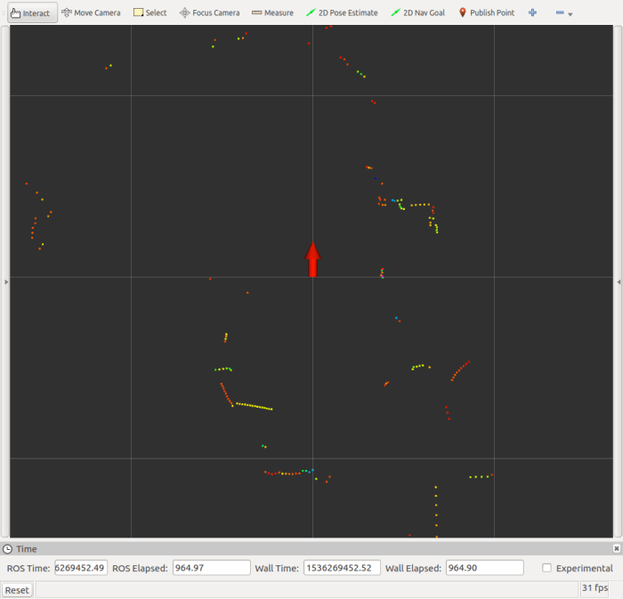
Now that I’ve decided to bring up the ROS navigation stack for Phoebe, where do I start? Well, the ROS Wiki page for the subject is always a good place to start, as they tend to have a tutorial for the subject. ROS navigation is no exception.

The first recommended page is actually a familiar sight – the brief overview on tf was required reading back when I first assembled the chassis. At the time, I could get away with a very simple static publisher, because I just had to tell ROS how and where my Neato LIDAR is mounted on my robot chassis. But now I guess I need to advanced to the next step and publish robot state. And this means describing Phoebe in more detail for ROS using a XML syntax called URDF (Unified Robot Descriptor Format).

So in order to bring up ROS navigation on Phoebe, the navigation wiki page has pointed me to robot state publisher and also the ROS URDF Tutorial. To learn one thing I had to learn another, the typical bootstrap process when learning something new.

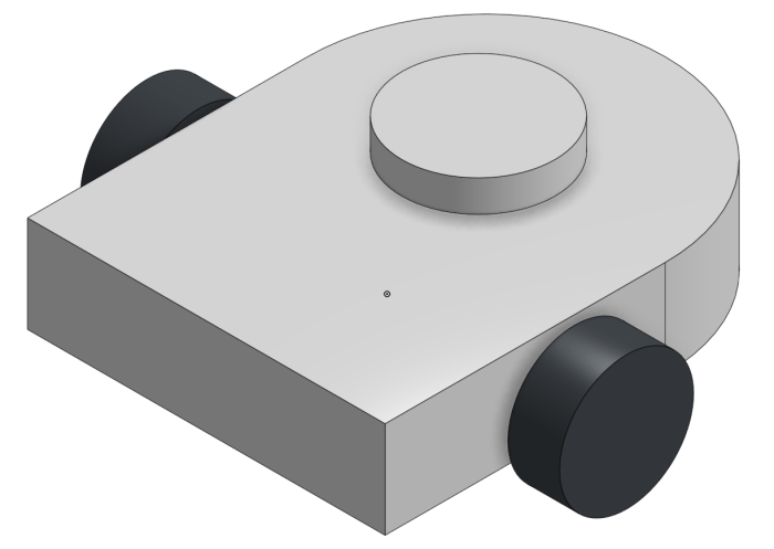
For the purposes of robot physics simulation, the robot should be described using very basic geometry: a combination of rectangular solids, cylinders, and spheres. This keeps the computation workload for collision detection simple. While the visual representation can be more complex than the collision detection representation, it doesn’t have to be. So for this first draft, I’ll just do a super simple Phoebe for visual representation, suitable for use in collision calculations if I get into that later.

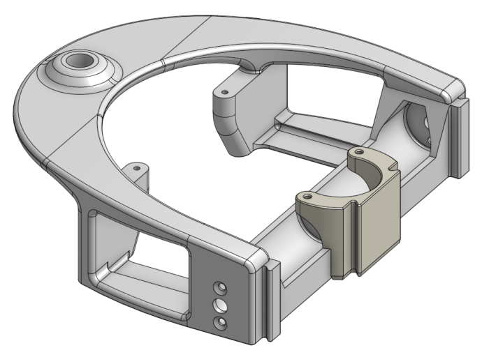
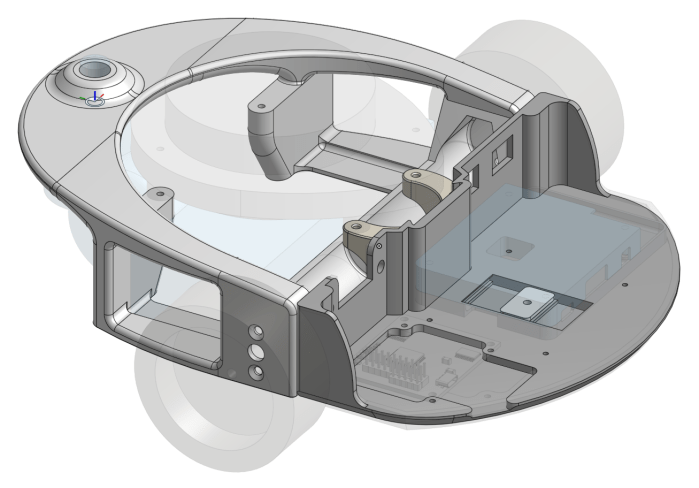
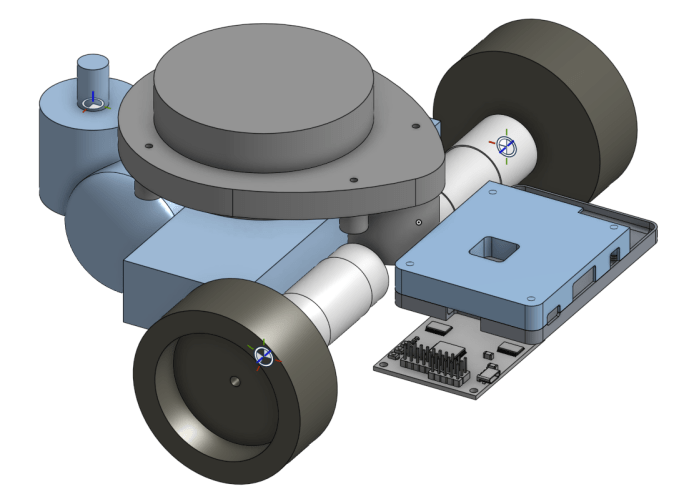
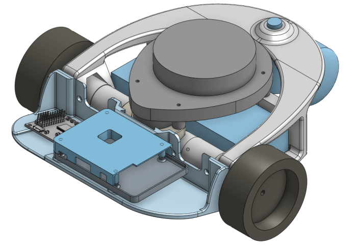
I started with Phoebe’s Onshape CAD file.

Phoebe CAD Full

Taking the critical dimensions, I created a simplified version in Onshape CAD using just rectangular boxes and cylinders. This exercise makes it a fairly straightforward exercise to translate into URDF.

Phoebe CAD Simplified

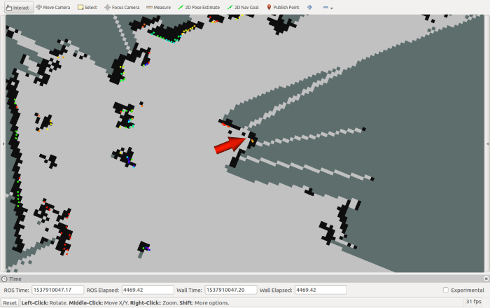
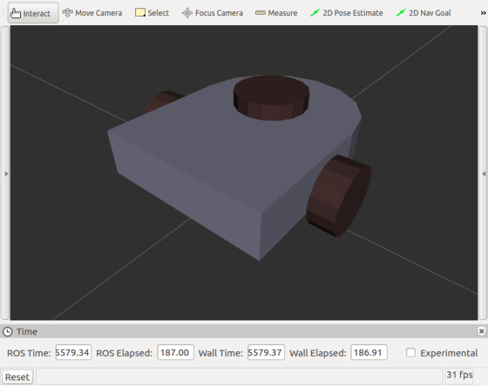
By measuring the dimensions in CAD, I could declare a few primitives with URDF and see what it looks like in RViz for comparison against CAD. Once the visual appearance is roughly correct, it’s time to tune the details and make sure they work for ROS functional purposes.

Phoebe RViz Simplified

(Cross-posted to Hackaday.io)

Next Phoebe Project Goal: ROS Navigation

rosorg-logo1When I started working on my own TurtleBot variant (before I even decided to call it Phoebe) my intention was to build a hardware platform to get first hand experience with ROS fundamentals. Phoebe’s Hackaday.io project page subtitle declared itself as a ROS robot for <$250 capable of SLAM. Now that Phoebe can map surroundings using standard ROS SLAM library ‘gmapping‘, that goal has been satisfied. What’s next?

One disappointment I found with existing ROS SLAM libraries is that the tutorials I’ve seen (such as this and this) expect a human to drive the robot during mapping. I had incorrectly assumed the robot would autonomously exploring its space, but “simultaneous location and mapping” only promises location and mapping – nothing about deciding which areas to map, and how to go about it. That is left to the human operator.

When I played with SLAM code earlier, I decided against driving the robot manually and instead invoked an existing module that takes a random walk through available space. A search on ROS Answers web site for something more sophisticated than a random walk resulted in multiple pointers to the explore module, but that code hasn’t been maintained since ROS “groovy” four versions ago. So one path forward is to take up the challenge of either update explore or write my own explorer.

That might be interesting, but once a map is built, what do we do with it? The standard ROS answer is the robot navigation stack. This collection of modules is what gives a ROS robot the ability to plan a path through a map, watch its progress through that plan, and update the plan in reaction to unexpected elements in the environment.

At the moment I believe it would be best to learn about the standard navigation stack and getting that up and running on Phoebe. I might return to the map exploration problem later, and if so, seeing how map data is used for navigation will give me better insights into what would make a better map explorer.

(Cross-posted to Hackaday.io)

Phoebe Accessory: HDMI Plug

In most ROS demonstrations, the robots are running through a pristine laboratory environment. Phoebe is built to roam my home, which is neither a laboratory or pristine. This became a problem when Phoebe ran across some dust bunnies and picked them up with its leading edge.

When choosing an orientation for Raspberry Pi 3 on Phoebe’s electronics tray, I chose to make the HDMI port accessible so I could connect a monitor as necessary. This resulted in that port facing forward along with the micro-USB power port and the headphone jack. All three of these ports were plugged up with debris when Phoebe explored some paths less well-traveled.

After I cleaned up the mess, all three ports appeared to work, but I was worried about Phoebe encountering some less fluffy obstacles. The audio jack was not a high priority as Raspberry Pi default audio is notoriously noisy and I haven’t needed it. The power jack could be easily bypassed by sending power via the GIPO pins (as I’m doing right now). That leaves the HDMI port, which can be quite inconvenient if damaged.  If I need a screen on a Pi with damaged HDMI port, I’d need to buy or borrow a screen that goes into the alternate DSI port like the official Raspberry Pi touchscreen.

Fortunately, there are little plastic plugs that come with certain HDMI peripherals for protection during shipping. In my case, I had a small red HDMI plug that came with my MSI video card. I installed it on Phoebe’s Raspberry Pi to protect the HDMI port against future debris encounters. Now Phoebe has a red nose. If it should glow I might have to rename my robot to Rudolph the Red Nosed Robot.

But it doesn’t glow, so Phoebe won’t get a name change.

Phoebe HDMI Plug

(Cross-posted to Hackaday.io)

Phoebe Accessory: Battery Voltage Monitor

And now, a few notes on some optional accessories. These aren’t required for anyone building their own Phoebe, but are nice to have.

The first item is a battery voltage meter and alarm. While Phoebe can monitor battery voltage in software via Roboclaw API, I also wanted an always-available physical readout of battery voltage. On Sawppy I thought I just needed to show the battery’s output voltage, but the number is only good if I could read it. During Sawppy’s all-day outing at JPL, California sunlight was too bright to read the number and I couldn’t tell when my battery dropped below recommended level for lithium chemistry batteries.

Searching for a better solution, I found these battery voltage alarms (*). Not only do they display voltage, when the level gets too low they also sound a buzzer. Judging by its product description, these were designed for remote-control aircraft where it’s not convenient to read a small number up in the air.

The downside is that the alarm is designed to be audible while up in the air and buried inside a fuselage. When it is on the ground and right in front of my face, it is a piercing shriek. Which isn’t so bad if it only occurs during low battery… but it also sounds a test beep when I first plug it in. It is loud. Very loud. To save my eardrums, the alarm buzzer has been muffled with some cotton pulled from a cotton swab. It’s still loud, but no longer gives me a headache afterwards.

I’ve also soldered a JST-XH connector onto the unpolarized input pins to fit my battery’s balance charging plug. Having a polarized connector helps make sure I don’t plug the battery in backwards. Those exposed pins are also a short-circuit risk, which I crudely mitigated by wrapping a layer of servo tape around them. Finally servo tape is used to secure the alarm to Phoebe’s backbone.

Now I can drive Phoebe around the house, even out of sight, confident that if I ever run the battery too low I’ll be notified with an alarm.

(Cross-posted to Hackaday.io)


(*) Disclosure: As an Amazon Associate I earn from qualifying purchases.

Robot Disorientation Traced To Timing Mismatch

Once the Roboclaw ROS Node‘s wheel parameters were updated to match the new faster motors, Phoebe went on a mapping run. And the results were terrible! This is not a complete surprise. Based on previous experimentation with this LIDAR module, I’ve seen its output data distorted by motion. It doesn’t take a lot of motion – even a normal human walking pace is enough to cause visible distortion. So now that Phoebe’s motors are ten times faster than before, that extra speed also adds extra distortion.

While this is a problem, it might not be the only problem behind the poor map. I decided to dig into an anomaly I noticed while using RViz to calibrate wheel data against LIDAR data: there’s some movement that can’t be entirely explained by a LIDAR spinning at 240 RPM.

The idea behind this odometry vs. LIDAR plot on RViz is to see if wheel odometry data agrees with LIDAR data. My favorite calibration surface is a door – it is a nice flat surface for LIDAR signal return, and I could swing the door at various angles for testing. In theory, when everything lines up, movement in the calculated odometry would match LIDAR observed behavior, and everything that is static in the real world (like the door) would be static in the plot as well.

In order to tune the base_width parameter, I looked at the position of the door before turning, and position after turning. Adjusting base_width until they line up, indicating odometry matches LIDAR. But during the turn, the door moved relative to the robot before finishing at the expected position.

When Phoebe started turning (represented by red arrow) the door jumped out of position. After Phoebe stopped turning, the door snapped back to position. This means non-moving objects appear to the robot as moving objects, which would confuse any mapping algorithm.

Odom LIDAR Mismatch No Hack

I chased down a few dead ends before realizing the problem is a timing issue: the timestamp on the LIDAR data messages don’t line up with the timestamp on odometry messages. At the moment I don’t have enough data to tell who is at fault, the LIDAR node or the Roboclaw node, just that there is a time difference. Experimentation indicated the timing error is roughly on the order of 100 milliseconds.

Continuing the experiment, I hard-coded a 100ms timestamp delta. This is only a hack which does not address the underlying problem. With this modification, the door still moves around but at least it doesn’t jump out of place as much.

Odom LIDAR Mismatch 100ms hack

This timing error went unnoticed when Phoebe was crawling extremely slowly. But at Phoebe’s higher speed this timing error could not longer be ignored. Ideally all of the objects on the RViz plot would stay still, but we clearly see nonuniform distortion during motion. There may be room for further improvement, but I don’t expect I’ll ever get to ideal performance with such an inexpensive LIDAR unit. Phoebe may end up just having to go slowly while mapping.

(Cross-posted to Hackaday.io)

Using RViz to Validate Motor Movement Against LIDAR Data

The Roboclaw ROS node is responsible for calculating odometry information based on encoder values read from each wheel. In order to translate them into standard ROS units, it needs two parameters:

  • ticks_per_meter : To calculate physical distance traversed by each wheel, the code needs to know how many encoder counts it takes for the wheels to travel one meter.
  • base_width : To calculate how much the robot has turned, the code needs to know how far apart the two drive wheels are placed.

Both of these values needed updating after upgrading Phoebe to the second chassis. I got impatient with the slow speed of the first draft, so the motor gearboxes were changed out with ones that deliver less torque and precision but much faster top speed. This change of gearing would need a new ticks_per_meter value. And the second chassis is slightly wider than the first, which obviously changes the base_width value. Both of these could be calculated on paper, but that is only a starting point. Real world is always a little different from the theoretical and needs a little adjustment.

The easiest place to start is ticks_per_meter. Phoebe is placed on a flat surface, next to a ruler, and commanded to drive straight forward for a short distance. During this activity, the odometry data is monitored with rostopic echo /odom to see how far Phoebe thinks it has actually gone. If the ruler said Phoebe didn’t go as far as it thought it did, increase ticks_per_meter. If Phoebe overshot, reduce that value.

Once wheel travel was verified with a ruler, LIDAR is added to the picture. RViz is commanded to plot odometry data and LIDAR data together, and Phoebe is placed facing a door serving as a large flat surface for reference. The red arrow represents where Phoebe thinks it is, facing the horizontal line representing its LIDAR’s view of the door.

Phoebe Door Test 1 Start

Then Phoebe was commanded to move backwards 0.5m. If odometry data agrees with LIDAR data, the movement away from door and the door’s distance from robot would match, canceling each other out so the line representing the door would not move on the RViz plot. It looks like the ruler calibration worked out well, as we’re only a tiny bit off.

Phoebe Door Test 2 Back 0.5m.png

Once distance was verified, we move on to rotation. Command Phoebe to make a 90 degree turn clockwise and see if LIDAR plot agrees. Again, ideally the turn calculated from odometry would agree with the LIDAR plot, leaving the door in roughly the same place on the RViz plot. Ideally.

Phoebe Door Test 3 90 Deg Right Bad

In this case, however, the door shows a minor clockwise rotation. This change of position in LIDAR data indicates Phoebe didn’t turn as far as it thought it did. To adjust parameters so Phoebe’s calculations better align with actual motion, we can increase the base_width parameter. And if the door had rotated the other way (Phoebe turned further than it thought it did) the parameter should be decreased.

(Cross-posted to Hackaday.io)

Phoebe vs. Office Chair Round 2

Phoebe was built to roam my house, but the first draft chassis was unable to do so effectively due to a few problems that the second chassis aimed to solve. The first one was ground clearance, which was solved by raising the main chassis and sloping the bottom of the electronics tray. Sloping that leading edge gives Phoebe a better approach angle for smoothly transitioning between floor surfaces.

The second major problem was the LIDAR scanner’s height: it was too high to see the legs of an office chair. Hence the other major goal of the second chassis was to lower the LIDAR mounting point and hopefully bring an office chair’s legs into plane of view.

Placing the newly rebuilt Phoebe next to the chair looks promising at first glance. Unlike the taller first chassis, the LIDAR’s horizontal plane of sight is now low enough it should be able to see the legs.

Phoebe vs Chair Round 2

The proof is in the occupancy grid, and the RViz plot shows that Phoebe can now see the legs of the chair blocking its way.

Phoebe Sees Chair Legs

It’s not a very solid detection, though. Something about the surface texture and/or angle of the plastic results in a weak laser return.  And there’s the risk of a leg going undetected when if approached from the end, as the dark sloped rounded end of the chair leg is nearly invisible to LIDAR.

But it’s a huge improvement from before, where the LIDAR was too high to see any part of the starfish pattern. It’s good enough for us to proceed with the next task: integrate Phoebe’s new faster wheel drive motors into the system.

(Cross-posted to Hackaday.io)

Phoebe Chassis 2 Electronics Tray

Phoebe’s first chassis stacked vertically: motors and wheels on the bottom, electronics in the middle, and LIDAR up top. That had to change for chassis 2 due to the desire to lower height of LIDAR for better obstacle visibility. The electronics were squeezed to the front where they now occupy a tray dedicated to all electronics components. This tray was originally separated because the chassis would otherwise be too big to print on my printer. But as it turns out the separation also made it more convenient to iterate through ways to install electronics without having to reprint everything.

The unpredictability came from wiring: I didn’t want to cut wires attached to components (the LIDAR, the motor+encoder, and battery) to length, so there needs to be room to coil extra wire. I also needed to run power wires to voltage regulators. One producing 3 Volts for LIDAR spin motor, a second one adjusted to 5 volts for Raspberry Pi. The Roboclaw handles battery power directly to the motors, and has its own voltage regulator to drive its internal logic circuits plus motor encoders.

Phoebe Chassis 2 Electronics Tray Iterations

It took two iterations to get everything to fit nicely, but once I started driving Phoebe chassis 2 around I found a new problem: approach angle. Chassis 2 has a higher ground clearance relative to its predecessor, and I held the same ground clearance for the electronics tray. However, because the tray is hanging out in front, having the same clearance is not enough when transitioning between different floor heights. When going from linoleum to carpet, thick carpet can get caught on the tray’s front lip preventing further forward progress. And when transition from carpet to linoleum, the front lip contacts the linoleum as the rear caster is still sitting on carpet. They lift the two drive wheels off the ground and Phoebe is stuck, helplessly spinning drive wheels.

The solution is to angle the tray upwards so the bottom of the tray becomes a skid plate. This helps transitioning from linoleum to carpet, and does not pull the drive wheels off the ground when going from carpet to linoleum.

phoebe-v2-side-view-isometric with arrow

And thus we inadvertently find the third benefit of printing the electronics tray as a separate piece: we can print it at a different angle, with its flat bottom on the print bed, avoiding the need for print supports to generate the sloped surface.

With these changes, Phoebe can now roam through my entire house, freely traversing across the various terrains of a normal household.

Phoebe Chassis 2 Carpet to Linoleum

(Cross-posted to Hackaday.io)

Phoebe Chassis 2 Backbone

Once I aborted plans to split Phoebe’s second chassis design into top and bottom decks, most of the workload was concentrated into a main backbone structure that will support all three wheels – two motorized driven wheels and one caster wheel. It will also support the battery, which is the heaviest single component, and the scanning LIDAR unit salvaged from a Neato robot vacuum.

Aside from their size and weight, the common thread with these components is that I don’t expect them to change very much in Phoebe’s future. They are all of the core components of a TurtleBot: differential-drive for mobility and a LIDAR to sense its surroundings. If either of those primary items change, it’s really an entirely different robot and no longer an iteration of Phoebe.

What I do expect to evolve at a much higher rate are the electronics that will control the motors and read the sensors (both motor encoder and LIDAR.) They will be mounted on a separate electronics equipment tray which will be mounted to the front end of chassis 2 backbone. More detail on that later.

For rigidity I had planned to make everything a single piece, but I wasn’t able to figure out a good way to make a 3D-printable structure that can support the LIDAR module above the motors and still leave enough space for those motors to be installed. So the LIDAR front support became a separate C-shaped piece that is clipped onto the backbone after motors are installed.

Phoebe 2 Mechanical Backbone

Other than that concession to practicality, Phoebe’s new backbone is a single rigid structure that links all wheels together and supports everything except the electronics. Once I had all the major connection points sketched out, I put effort into aesthetics design and making the backbone look more like one smoothly blended and integrated unit. The arch connecting all three wheels reminded me of a similar arch aboard Star Trek: The Next Generation‘s Enterprise-D bridge. (It held computer displays for the officers on duty standing behind Captain Picard.)

Printing this design requires support structures for that arch, and took over 8 hours to print. (Plus another half hour for the separate C-shaped clip.) I’m pleased with the results and, as expected, it has held up well through multiple iterations of the electronics tray.

(Cross-posted to Hackaday.io)

Phoebe Chassis 2: Dividing Top/Bottom vs. Front/Back

With help of Onshape in-context modeling, I started creating a chassis for Phoebe to support an arrangement that fit every component compactly like a 3D puzzle.

It was immediately obvious that I would not be able to print the entire chassis in one piece, as the footprint is greater than my 3D printer’s 200mm x 200mm print area. As I typically design parts to be printed without supports, I started with an approach that would split the chassis into top/bottom pieces. The top deck would support Phoebe’s caster wheel and Neato LIDAR. The bottom deck would support all the electronics. Then the battery compartment and motors would be bolted in between the top and bottom decks.

Phoebe Bottom Deck Draft

Here’s one of the drafts of the low deck, with a representative sample motor, battery, and Pi. I was not terribly confident about placement of the electronics. I could model the individual parts in CAD but there will be a lot of wires going between them. Wires take up space, and they are flexible with spring that push against each other, making them difficult to model accurately in CAD.

I looked at the electronics tray here and foresaw printing several iterations as I worked through wiring challenges. The bottom deck also includes part of the battery tray and motor mounts. Since these two things aren’t expected to change, printing each iteration would waste a lot of time going over the same thing. This was the first strike against a top/bottom split.

The second strike is physical strength: since top deck would house the caster wheel sticking out the back, it has leverage to put a lot of stress on however the top and bottom decks will be joined together. No matter if I used glue, or bolts, or something else. Foreseeing the structural loads, I decided it made more sense to have a single strong backbone connecting both motorized wheels and caster wheel.

This will require printing with supports, but the resulting strength should be worth the effort, and it isn’t likely to change as I evolve through the electronics. So I abandoned the top/bottom split and changed to a front-back split, with the strong single piece supporting all mechanical parts in the back.

(Cross-posted to Hackaday.io)

Onshape In-Context Modeling For Phoebe’s Second Chassis

Digitally laying out major components of a project in 3D space is something I’ve done for many projects, from my FreeNAS Box, to Luggable PC, to Sawppy the Rover. Doing it again for to figure out a more compact layout for Phoebe’s second chassis wasn’t a big deal in itself. However, this time the exercise will have a much more direct impact, thanks to a relatively new feature in Onshape.

For my past exercises, once I had decided upon a layout I would take measurements of relative position and dimensions of spaces between them. I would then copy those numbers to new drawings and build parts from those drawings. This workflow is functional but feels silly. The layout information is in the computer, why can’t I use them back in the drawings for components?

I’m not sure what the answer is, but whatever they may be, they are no longer relevant: modern CAD software now offer the ability to take assemblies of parts and use information from the assembly in drawings. They go by various names. SolidWorks documentation refers to this as top-down design. Onshape calls their version in-context modeling. Whatever the name, it’s a system that allowed me to reverse my design process. In the first chassis, I built a simple plate and bolt parts on it as I went. Now with the help of in-context modeling, I’ve arranged all the components in a game of 3D puzzle before creating a chassis to deliver that arrangement.

Using in-context modeling, I don’t have to copy & paste dimensions and risk introducing errors in the process. I also have the option to move parts around my layout and have all design dimensions update automatically. That last part doesn’t work quite as well as advertised, though I’m not sure what’s fundamental problem and what are just minor bugs they’ll fix later. But it works well enough today for me to believe in-context modeling will have a role in all my future projects.

In Context Editing 2

(Cross-posted to Hackaday.io)

Phoebe’s Component Layout Is A 3D Jigsaw Puzzle

Phoebe’s first chassis was just a rough draft to get first hand exposure trying to get all the parts my TurtleBot variant needed to talk and work with each other. What that exposure taught me is I need to improve packaging space efficiency and create a much more compact robot. Only then could I satisfy the competing requirements of increasing ground clearance and lowering LIDAR sensor height.

To work on this puzzle in three dimensions, I started by holding parts up against each other. But I quickly ran out of hands to track all their related positions so I moved on to do it digitally. First I created 3D representations of the major parts. They didn’t have to be very detailed, just enough for me to block out the space they’ll need. Then they were all imported into a single Onshape assembly so I could explore how to fit them together.

In Context Editing

I turned the caster forward, as if the robot was travelling backwards, because that position represents the maximum amount of space it needs. My battery is the heaviest single component, so for best balance it needs to be mounted somewhere between the drive wheels and the caster. Relative to the first draft chassis, the battery was rotated to allow more ground clearance, but that also pushed the caster a little further back than before.

In the first chassis, electronic components like the Roboclaw motor controller and Raspberry Pi 3 were sandwiched above the motors and below the LIDAR. They’ve been moved to the front in order to lower LIDAR height. The lowest point of the LIDAR module – its spinning motor – was dropped in between wheel drive motors. This required turning the LIDAR 180 degrees – what used to be “front” is now “back” – but we should be able to describe that frame of reference by updating its corresponding ROS component transform.

(Cross-posted to Hackaday.io)

Speedy Phoebe: Swapping Gearbox For 370 Motors

The first rough draft chassis for Phoebe worked well enough for me to understand some pretty serious problems with that design. Now that I have a better idea what I’m doing, it’s time to start working on a new chassis incorporating lessons learned. And since all the components will be taken apart anyway, it would be a good time to address another problem: Phoebe’s speed. More precisely, the lack thereof.

Phoebe’s motor + encoder + gearbox unit was borrowed from the retired parts bin for SGVHAK Rover. Since they were originally purchased to handle steering, priority was on precision and torque rather than speed. It worked well enough for Phoebe to move around, but their slow speed meant it took quite some time to map a room.

The motor mounts used for Phoebe’s first draft chassis were repurposed from a self-balancing robot toy, which had a similar motor coupled with a different ratio gearbox. That motor was not suitable for ROS work because there was no encoder on the motor, but perhaps we could swap its gearbox with the motor that does have an encoder.

Identical output shaft and mount

Here’s the “Before” picture: Self-balancing robot motor + gearbox on the left, former SGVHAK rover steering encoder + motor + gearbox on the right. The reason I was able to use the self balancing robot’s motor mount and wheel is because they both had the same output shaft diameter and mount points. While they have identical diameter, the steering gearbox is noticeably longer than the balancing robot gearbox.

Both Are 370 Motors

Both of these motors conform to a generic commodity form factor called “370”. A search for “370 motor” on Alibaba will find many companies making different motors with different options of voltage, speed, etc. All are physically similar in size. Maybe even identical? As for what “370” means… best guess is that it originally referred to overall length of the motor at 370 millimeters. It doesn’t specifically mean anything for remaining motor dimensions, but “370 motor” has probably become a de-facto standard. (Like 608 bearings.)

After a few screws were removed, both gearboxes were easily disassembled. We can see a few neat things: the plate mounting the gearbox to the motor had multiple holes to accommodate three different patterns. Either these gearboxes were designed to fit on multiple different motors, or some 370 motors are made with different bolt patterns than others.

Gearboxes Removed

Fortunately, both motors (one with encoder, one without) seem to have the same bolt pattern. And more importantly – the gear mounted on the motor output shaft seems to be identical as well! I don’t have to pull the gear off one shaft and mount it on another, which is great because that process tends to leave the gear weaker. With identical gears already mounted on the motor output shaft, I can literally bolt on the other gearbox and complete the swap.

After - Gearboxes swapped

Voila! The motor with encoder now has a different gear ratio that should allow Phoebe to run a lot faster. The slow one was advertised to be 227:1 ratio. I don’t have specification sheet for the fast gearbox, but turning one shaft and counting revolutions of the other indicates a roughly 20:1 ratio. So theoretically Phoebe’s top speed has been increased ten-fold. Would that be too fast and cause Phoebe to run out of control? Would it be unable to slow to a sufficiently low crawl speed for Phoebe to cautiously explore new worlds? We won’t know until we try!

(Cross-posted to Hackaday.io)

Phoebe’s Nemesis: Office Chair

A little real-world experience with Phoebe has revealed several problems with my first rough draft chassis design. The second problem on the list is Phoebe’s LIDAR height: It sits too high to detect certain obstacles like an office chair. In the picture below, Phoebe has entered a perilous situation without realizing it. The LIDAR’s height meant Phoebe only sees the chair’s center post, thinking it is a safe distance away, blissfully ignorant of chair legs that have completely blocked its path.

Phoebe Faces Office Chair

Here is the RViz plot of the situation, representing Phoebe’s perspective. A red arrow indicates Phoebe’s position and direction. Light gray represents cells in the map occupancy grid thought to be open space, and black are cells that are occupied by an obstacle. Office chair’s center post is represented by two black squares at the tip of the red arrow, and the chair’s legs are absent because Phoebe never saw them with LIDAR.

Phoebe and Office Chair Post

This presents obvious problems in collision avoidance as Phoebe can’t avoid chair legs that it can’t see. Mounting height for Phoebe’s LIDAR has to be lowered in order to detect office chair legs.

Now that I’ve seen this problem firsthand, I realize it would also be an issue for TurtleBot 3 Burger. It has a compact footprint, and its parts are built upwards. This meant it couldn’t see office chair legs, either. But that’s OK as long as the robot is constrained to environments where walls are vertical and tall, like the maze seen in TurtleBot 3 Navigation demo. Phoebe would work well in such constrained environments too, but I’m not interested in constrained environments. I want Phoebe to roam my house.

Which leads us to Waffle Pi, the other TurtleBot 3 model. it has a larger footprint than the Burger, but it is a squat shape allowing LIDAR to be mounted lower and still have a clear view all around the top of the robot.

So I need to raise the bottom of Phoebe for ground clearance, and also lower the top for LIDAR mount. If the LIDAR can be low enough to look just over the top of the wheels, that should be good enough to see an office chair’s legs. Will I find a way to fit all of Phoebe’s components into this reduced height range? That’s the challenge at hand.

(Cross-posted to Hackaday.io)

Phoebe’s Nemesis: Floor Transitions

Right now my TurtleBot-based robot Phoebe is running around on a very rough first draft of chassis design. It was put together literally in an afternoon in the interest of time. Just throw the parts together so we can see if the idea will even work. Well, it did! And I’m starting to find faults with the first draft chassis that I want to address on the next version for a much better thought-out design.

The first fault is the lack of ground clearance. When I switched my mentality from the rough terrain capable Sawppy rover to a flat ground TurtleBot like Phoebe, I didn’t think the latter would need very much ground clearance at all. As a result, Phoebe’ battery pack hung between the driving wheels and caster, with only a few millimeters of clearance between the bottom of the battery tray and the ground.

Phoebe Ground Clearance Flat

If I’m not climbing rocks, I asked myself, why would I need ground clearance?

Well, I’ve found my answer: my home has rooms with carpet, rooms with linoleum, and rooms with tile. The transition between these surfaces are not completely flat. They’re pretty trivial for a walking human being, but for poor little Phoebe they are huge obstacles. Driving across the doorway from carpet to linoleum would cause Phoebe to get stuck on its battery belly.

Phoebe Ground Clearance Threshold

“More ground clearance” is a goal for Phoebe’s next chassis.

(Cross-posted to Hackaday.io)

ROS Notes: Map Resolution

Now that I’m driving my TurtleBot-derived robot Phoebe around and mapping my house, I’m starting to get some first-hand experience with robotic mapping. One of the most fascinating bits of revelation concerns map resolution.

When a robot launches the Gmapping module, one of the parameters (delta) dictates the granularity of the occupancy grid in meters. For example, setting it to 0.05 (the value used in TurtleBot 3 mapping demo) means each square in the grid is 0.05 meters or 5 cm on each side.

This feels reasonable for a robot that roams around a household. Large objects like walls would be fine, and the smallest common obstacle in a house like table legs can reasonably fill a 5cm x 5cm cell on the occupancy grid. If the grid cells were any larger, it would have trouble properly accounting for chair and table legs.

Low Resolution Sharp Map 5cm

So if we make the grid cells smaller, we would get better maps, right?

It’s actually not that simple.

The first issue stems from computation load. Increasing resolution drastically increases the amount of memory consumed to track the occupancy grid, and increases computation requirements to keep grid cells updated. The increase in memory consumption is easy to calculate. If we halve the grid granularity from 5cm to 2.5cm, that turns each 5cm square into four 2.5cm squares. Quadrupling the memory requirement for our occupancy grid. Tracking and maintaining this map is a lot more work. In my experience the mapping module has a lot harder time matching LIDAR scan data to the map, causing occasional skips in data processing that ends up reducing map quality.

The second issue stems from sensor precision. An inexpensive LIDAR like my unit salvaged from a Neato robot vacuum isn’t terribly precise, returning noisy distance readings that varies over time even if the robot and the obstacle are both standing still. When the noise exceeds map granularity, the occupancy grid starts getting “fuzzy”. For example, a solid wall might no longer be a single surface, but several nearby surfaces.

High Resolution Fuzzy Map 1cm

As a result of those two factors, arbitrarily increasing the occupancy map resolution can drastically increase the cost without returning a worthwhile improvement. This is a downside to going “too small”, and it was less obvious than the downside of going “too large.” There’s a “just right” point in between that makes the best trade-offs. Finding the right map granularity to match robots and their tasks is going to be an interesting challenge.

(Cross-posted to Hackaday.io)

Phoebe The Cartographer

Once odometry calculation math in the Roboclaw ROS driver was fixed, I could drive Phoebe (my TurtleBot variant) around the house and watch laser and odometry data plotted in RViz. It is exciting to see the data stream starting to resemble that of a real functioning autonomous robot! And just like all real robots… the real world does not match the ideal world. Our specific problem of the day is odometry drift: Phoebe’s wheel encoders are not perfectly accurate. Whether from wheel slippage, small debris on the ground, or whatever else, they cause the reported distance to be slightly different from actual distance traveled. These small errors accumulate over time, so the position calculated from odometry becomes less and less accurate as Phoebe drives.

The solution to odometry drift is to supplement encoder data with other sensors, using additional information can help correct for position drift. In the case of Phoebe and her  TurtleBot 3 inspiration, that comes in courtesy of the scanning LIDAR. If Phoebe can track LIDAR readings over time and build up a map, that information can also be used to locate Phoebe on the map. This class of algorithms is called SLAM for Simultaneous Location and Mapping. And because they’re fundamentally similar robots, it would be straightforward to translate TurtleBot 3’s SLAM demo to my Phoebe.

There are several different SLAM implementations available as ROS modules. I’ll start with Gmapping because that’s what TurtleBot 3 demo used. As input this module needs LIDAR data in the form of ROS topic /scan and also the transform tree published via /tf, where it finds the geometry relationship between odometry (which I just fixed), base, and laser. As output, it will generate an “occupancy grid”, a big table representing a robot’s environment in terms of open space, obstacle, or unknown. And most importantly for our purposes: it will generate a transform mapping map coordinate frame to the odom coordinate frame. This coordinate transform is the correction factor to be applied on top of odometry-calculated position, generated by comparing LIDAR data to the map.

Once all the pieces are in place, Phoebe can start mapping out its environment and also correct for small errors in odometry position as it drifts.

SLAM achievement: Unlocked!

Phoebe GMapping

(Cross-posted to Hackaday.io)

Roboclaw ROS Driver: Odometry Calculation Reversal

rosorg-logo1I’m making good progress on integrating ROS into my TurtleBot variant called Phoebe. I’ve just configured RViz to plot Phoebe’s location as reported by Roboclaw ROS driver‘s odometry information topic /odom. On the same plot, I’ve also placed data reported by Phoebe’s scanning LIDAR. Everything looked good when I commanded Phoebe to drive forward, but the geometry went askew as soon as Phoebe started turning. The LIDAR dots rotated one way, and the odometry reporting arrow rotated another. Something is wrong in the geometry calculation code.

For this particular problem I knew exactly where to start looking. When I assembled Phoebe, I knew I needed to configure motors in the way expected by the Roboclaw ROS driver. The README didn’t explicitly say which motor went on which side, so I went into the source code and got conflicting answers. In the motor driving routine (cmd_vel_callback) it performed calculation for right wheel motion and sent it to motor 1, and left wheel motion went to motor 2.

However, this doesn’t match encoder calculation code. The method EncodeOdom::update_publish expects its parameters to be (enc_left, enc_right). In method Node::run, it retrieves encoder values from motor 1 and saves it in variable enc1, and enc2 for motor 2, then calls update_publish(enc1, enc2). Which would treat encoder value of motor 1 as enc_left instead of enc_right, the opposite of what we’d want.

So the fact data on /odom is going the wrong way was not a surprise, but why didn’t the LIDAR transform also suffer the same problem? This was traced down to an earlier change submitted as a fix for the reverse transform problem – that commit added a negative sign in front of the calculated angle when broadcasting odom -> base_link transform. But that only masked and didn’t fix the underlying problem. The transform might look right, but /odom data is still all wrong, and variables like self.last_enc_right is actually holding the left side value.

The correct fix would be to reverse the parameter order when calling EncodeOdom::update_publish which correctly assigns encoder 1 count the right motor, and encoder 2 the left motor. And with the underlying problem fixed, we no longer need the negative sign so that can be deleted.

With this fix, Phoebe’s laser plot and odometry plot in RViz appear to agree with each other and both correspond correctly to the direction Phoebe is turning. I’ve submitted this fix as a pull request on the Roboclaw ROS driver.

Driving Miss Phoebe (Not Self-Driving… Yet)

Now that the Roboclaw ROS node is configured for Phoebe TurtleBot’s physical layout, and the code is running reliably instead of crashing, I can drive it around as a remote control car. This isn’t the end goal, of course. If all I wanted was a remote control car there were far cheaper and easier ways to get here. Right now the goal is just to verify functionality of the drive system and that it is properly integrated into the ROS infrastructure.

In order to send driving commands to Phoebe, I need something that publishes to the command & velocity topic /cmd_vel. On an autonomous robot, the navigation code would be in charge of sending these commands. But since it’s a pretty common task to move a robot around manually, there are standard ROS packages to drive a robot via human commands. The most basic is teleop_twist_keyboard which allows driving by pressing keys on a keyboard. Alternatively there is teleop_twist_joy for driving via a joystick.

Those remote control (or ‘tele operation’ in ROS parlance) nodes worked right off the bat, which is great. But I quickly got bored with driving Phoebe around on the carpet in front of me. First I launched RViz to visualize scanning LIDAR data as I did before. This was enough for me to drive Phoebe beyond my line of sight, watching surroundings in the form of the laser scan dots. After I verified that still worked, I stepped up the difficulty: I wanted RViz to plot laser data on top of odometry data in order to verify that Roboclaw ROS node is generating odometry data correctly.

To do this, I needed to participate in the ROS coordinate transform stack, the infrastructure to track all the frames of reference for relating robot components to each other in physical space. The Roboclaw ROS node publishes a transform to relate a robot’s position reference frame base_link to the odometry origin reference frame odom. The LIDAR ROS node publishes its data relative to its own neato_laser reference frame. As the robot builder, it was my job to write a transform to relate neato_laser frame to Phoebe’s base_link frame. Fortunately, ROS transform tutorials covered this exact task and I quickly got my desired RViz plot.

RViz with LaserScan and Odometry

It looks like the LIDAR scan plot from earlier, but now there’s an arrow indicating Phoebe’s position and direction. The bigger change not visible in this screen shot is that RViz is now plotting in the odometry frame. This means we no longer watch strictly from Phoebe’s viewpoint  where robot stays in the center of screen. The plot is now in odometry frame, and Phoebe should be moving relative to the map.

I drove Phoebe forward, and was happy to see the laser scan stayed still relative to the map and the red arrow representing Phoebe moved forward. But when I started turning Phoebe, the red arrow turned one way and the LIDAR plot moved the opposite way.

Something is wrong in the coordinate transform data, time for some debugging…

Roboclaw ROS Driver: Add Thread Synchronization

rosorg-logo1I now turn my attention to finding the root cause of random sporadic failures when the Roboclaw ROS driver makes calls into Roboclaw API. The most common symptom of these failures is the TypeError I addressed earlier, but avoiding crash by TypeError is only a band-aid. There were still other issues. Sometimes Phoebe’s movement stutters. And even more mysteriously, sometimes when Phoebe was supposed to be standing still, it would twitch for a fraction of a second.

Looking into ROS logs, the node never intended to send a movement. But it does send a continuous stream of “run at speed X” commands at a rate of ten per second, whether it is trying to move the robot or not. When staying still, that stream continues at the same rate constantly sending “run at speed zero”. The fact that my robot twitches when it’s supposed to be standing still tells me that “run at speed zero” command is occasionally corrupted into a “run at speed X” command. Which starts the motor moving for 1/10th of a second until it is stopped by the next non-corrupted “run at speed zero” command.

Any time there is a random sporadic failure, my instinct is to look for places where threading collisions may be taking place. Programming for multi-threaded environments can get tricky. When I wrote code for SGVHAK Rover, the intent was to make that code easy to understand and pick up. In that spirit, I explicitly kept everything on a single thread to avoid multi-threading issues.

But now we’re playing in the major leagues and there’s no avoiding multiple threads. ROS itself runs across multiple processes and threads, so it could scale to robots that have multiple on board computers, each of which has multiple processing cores. Fortunately, ROS implementation takes care of almost everything, each ROS node just has to make sure they’re doing the right thing with their own private data.

There are at least three different ROS topics involved in this Roboclaw ROS node:

  1. Driving commands received via /cmd_vel
  2. Odometry computation broadcast to /odom
  3. Diagnostics information

Each ROS topic is processed in own thread, so given three topics, we should expect at least three different threads who might all call into Roboclaw API at the same time to perform their tasks. Armed with this knowledge, I looked for code managing cross-thread access. My plan was to review that code to see if I can find any obvious problems with it.

That plan was changed when I found no code managing cross-thread access. I guess its absence qualifies as an obvious problem and it would certainly explain the kind of behavior I saw.

Not being a Python expert, I cruised StackOverflow for a pattern I could use to implement Python thread synchronization. I decided it was most straightforward to use the with keyword described on one of the later replies on this “Semaphores on Python” thread. Using this pattern makes the code change delta very straightforward to read.

There were a few initial calls into Roboclaw API to set things up, I left those alone. But as soon as the code started kicking off events that would have other threads (specifically, when it started the diagnostics thread) every following call into Roboclaw API is synchronized by a threading.Lock() object. With this modification, we can guarantee that only one thread will be performing serial communication to Roboclaw motor controller at any given time, and avoid data corruption by multiple threads trying to talk to the serial port at the same time.

Phoebe ran smoothly and reliably after this work. No more stutter in motion, and no more twitching when standing still. I’ve submitted the fix as a pull request.