LIDAR Completes First Draft of Phoebe TurtleBot

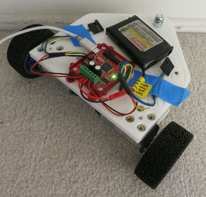
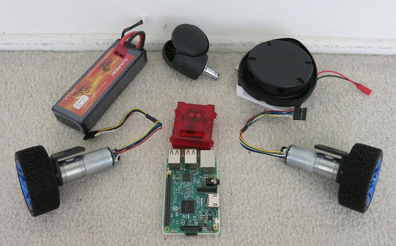
With the motors connected to Roboclaw, their direction and encoder in sync, and PID values tuned, Phoebe can be driven around via ROS /cmd_vel topic and report its movement via /odom. However, Phoebe has no awareness of its surroundings, which is where the LIDAR module comes in.

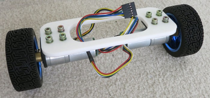
Salvaged from a Neato robot vacuum (and bought off eBay), it is the final major component to be installed on Phoebe. Since this is a rough first draft, the most expedient way to install the device is to drill a few holes for M3 standoffs, and mount the module on top of them. This allows the module clear lines of sight all around the robot, while sitting level with the ground. It is also installed as close to the center of the robot as practical. I don’t know if a center location is critical, but intuitively it seems to be a good thing to have. We’ll know more once we start driving it around and see what it does.

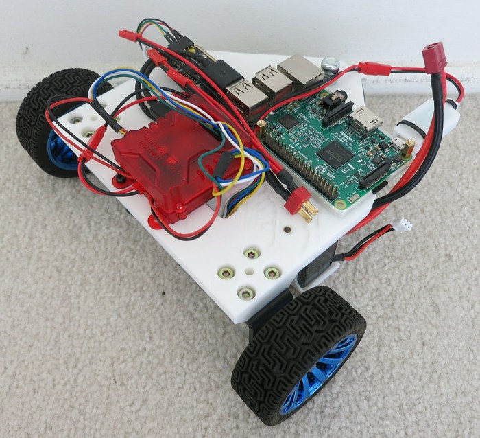
By this point the rough draft nature of the project is very visible. The LIDAR spin motor sticks out below the module the furthest, and the motor inadvertently sits right on top of the Raspberry Pi’s Ethernet port, which is the tallest point on a Pi. Raising the LIDAR high enough so they don’t collide left a lot of empty space between the two modules. Which is not wasted at the moment, because the wiring mess is getting out of control and could use all the space it can occupy.

The next version should lay things out differently to make everything neater. In the meantime, it’s time to see if we can drive this robot around and watch its LIDAR plot. And once that basic process has been debugged, that should be everything necessary to enable ROS projects to give Phoebe some level of autonomy.

Phoebe TurtleBot Stage 3 LIDAR

(Cross-posted to Hackaday.io)

Phoebe Receives Raspberry Pi Brain After PID Tuning

Once the motor’s spin direction was sorted out, I connected both encoders to verify A/B signals are in sync with motor direction. Again this is checked by commanding motor movement via Ion Studio software and watching the reported encoder value.

When wired correctly, encoder counter will increase when motor is commanded to spin in the positive direction, and decrease when motor spins negative. If hooked up wrong, the encoder value will decrease when the motor spins positive, and vice versa. The fix is simple: power down the system, and swap the A/B quadrature encoder signal wires.

Once the motor direction is verified correct, and encoder wires verified to match motor direction, we can proceed to the final phase of Roboclaw setup: determine PID coefficients for motor control.

PID tuning is something of a black art. Fortunately, while a perfect tune is very difficult to obtain, it’s not that hard to get to “good enough.” Furthermore, Ion Studio features an “Auto Tune” option to automatically find functional PID coefficients. During SGVHAK Rover construction we had no luck getting it to work and resorted to tuning PID coefficients manually. Fortunately, this time around Ion Studio’s automatic PID tuning works. I’m not sure what changed, but I’m not going to complain.

Once PID coefficients have been written to Roboclaw NVRAM, we no longer need to use the Windows-based Ion Studio software. From here on out, we can use a Raspberry Pi to control our motors. The Pi 3 was mounted so its microSD card remains accessible, as well as its HDMI port and USB ports. This meant trading off access to GPIO pins but we’re not planning to use them just yet so that’s OK.

Software-wise, the Raspberry Pi 3’s microSD card has a full desktop installation of ROS Kinetic on top of Ubuntu Mate 16.04 compiled for Raspberry Pi. In addition to all the Robotis software for TurtleBot 3, it also has a clone of the ROS control node, as well as a clone of the Neato LIDAR control node.

The wiring is not very neat or pretty but, again, this is just a rough first draft.

Phoebe TurtleBot Stage 2 Encoder Pi

(Cross-posted to Hackaday.io)

Establish Motor Directions For Phoebe TurtleBot

The first revision of Phoebe’s body frame has mounting points for the two drive wheels and the caster wheel. There are two larger holes to accommodate drive motor wiring bundle, and four smaller holes to mount a battery tray beneath the frame. Since this is the first rough draft, I didn’t bother spending too much time over thinking further details. We’ll wing it and take notes along the way for the next revision.

Phoebe Frame First Draft.PNG

After the wheels were installed, there was much happiness because the top surface of the frame sat level with the ground, indicating the height compensation (for height difference between motorized wheels and caster in the back) was correct or at least close enough.

Next, two holes were drilled to mechanically mount the Roboclaw motor control module. Once secured, a small battery was connected plus both motor drive power wires. Encoder data wires were not connected, just taped out of the way, as they were not yet needed for the first test: direction of motor rotation.

Phoebe TurtleBot Stage 1 PWM

The Roboclaw ROS node expects the robot’s right side motor to be connected as Motor #1, and the left as Motor #2. It also expects positive direction on both motors to correspond to forward motion.

I verified robot wiring using Ion Studio, the Windows-based utility published by the makers of Roboclaw. I used Ion Studio to command the motors via USB cable to verify the right motor rotates clockwise for positive motion, and the left motor counter-clockwise for positive motion. I got it right on the first try purely by accident, but it wouldn’t have been a big deal if one or both motors spun the wrong way. All I would have had to do is to swap the motor drive power wires to reverse their polarity.

(Cross-posted to Hackaday.io)

Test Frame To Help Arrange Phoebe’s Wheels

Since Phoebe will be a TurtleBot variant built out of stuff already in my parts bin, these parts won’t necessarily fit together well. The first thing to do is to figure out how to make the wheels work together. A simple test frame will mount Phoebe’s two drive wheels and see how they cooperate. And besides, building a two-wheel test chassis is how I’ve started many robot projects and that’s worked out well so far. So now let’s make another one to follow in the grand tradition of two wheel test chassis built to test parts going into SGVHAK Rover and Sawppy Rover.

Phoebe TurtleBot Two Wheel Test Frame

For Phoebe, this simple test chassis established the following:

  • I used a caliper to measure wheel mounting bracket dimensions, and they are accurate enough to proceed. They are spaced the correct distance apart, and their diameter is large enough for M4 bolts to slide through without being so large that the resulting wheel wobbles.
  • The 5mm thick slender connecting members are too weak. The next frame will have greater thickness and generally beefier structure.
  • I wanted a 20cm track. (Left-right distance between wheel centers.) I measured the dimensions for my wheel assembly but the measurements were a little off. Now I know how much to adjust for the next frame.
  • And most importantly: this frame allowed direct comparison of drive wheel resting height against caster wheel height. They were both awkward shapes to measure with a ruler so having the flat surface of a frame makes the measurement easier. Their relative height difference needs to be accounted for in the next frame in order to have a robot body that is level with the ground.

(Cross-posted to Hackaday.io)

Cost to Build Phoebe From Scratch

I chose components for Phoebe (“PB” or Parts Bin) TurtleBot because they were already available to me in one context or another. But not everyone has the same stuff in their own hoard. As an exercise for completeness, below is an estimate of what it would cost to build Phoebe if parts had to be purchased. Naturally, any parts already on hand can be subtracted from the cost. (The expected audience here is likely to have at least a Raspberry Pi 3 and battery to spare.)

  • Onboard computer: A Raspberry Pi 3 with microSD card, case, and DC power supply will add up to roughly $50.
  • Laser scanner: LIDAR salvaged off Neato robot vacuum cleaners are on eBay with “Buy It Now” prices of $50-$75 at time of this writing. People living in a major metropolis like Los Angeles can find entire Neato vacuums on Craigslist in a similar price range.
  • Motor controller: A Roboclaw with 7A capacity can be purchased directly from the manufacturer for $70. It is overkill for this project, but it was their entry-level product and it was already on hand. Lower-cost alternatives probably exist.
  • Gearmotor + Encoder + Wheel: Buying the motors I’m using from Pololu would be $35 each without bracket or wheel. However, similar units including mounting bracket and wheel are available on Amazon for $20 each.
  • Caster wheel: A caster wheel can be salvaged off a piece of broken furniture for free. If you have to buy a caster, don’t pay more than $3.
  • Battery: The battery pack I’m using are available for $25 each, but it’s far more battery than necessary for this project. A far smaller pack for $10-15 would be sufficient.

Sum total: $238, which still does not include the following:

  • 3D printer filament.
  • Electrical connectors and wiring.
  • Bolts, nuts, and other assembly hardware.

But given room for improvement (cheaper motor controller and battery) a whole package to build Phoebe from scratch should be possible for under $250, less than half of a TurtleBot 3 Burger.

(Cross-posted to Hackaday.io)


Disclosure: As an Amazon Associate I earn from qualifying purchases.

New Project: Phoebe TurtleBot

While my understanding of the open source Robot Operating System is still far from complete, I feel like I’m far enough along to build a robot to run ROS. Doing so would help cement the concepts covered so far and serve as an anchor to help explore new areas in the future.

Sawppy Rover is standing by, and my long-term plan has always been to make Sawppy smarter with ROS. Sawppy’s six-wheeled rocker-bogie suspension system is great for driving over rough terrain but fully exploiting that capability autonomously requires ROS software complexity far beyond what I could handle right now. Sawppy is still the goal for my ROS journey, but I need something simpler as an intermediate step.

A TurtleBot is the official ROS entry-level robot. It is far simpler than Sawppy with just two driven wheels and restricted to traveling over flat floors. I’ve been playing with a simulated TurtleBot 3 and it has been extremely helpful for learning ROS. Robotis will happily sell a complete TurtleBot 3 Burger for $550. This represents a discounted bundle price less than the sum of MSRP for all of its individual components, but $550 is still a nontrivial chunk of change. Looking over its capabilities, though, I’m optimistic I could implement critical TurtleBot functionality using parts already on hand.

  • Onboard computer: This one is easy. I have several Raspberry Pi 3 sitting around I could draft into the task, with all necessary accessories like a microSD card, a case, and power supply.
  • Laser scanner: Instead of the Robotis LDS-01, I’ll use a scanning LIDAR salvaged from a Neato robot vacuum that I bought off eBay for experimentation. Somebody has already written a driver package to report its data as a ROS /scan topic and I’ve already verified it sends data that the ROS visualization tool RViz can understand.
  • Motor controller: Robotis OpenCR is a very capable board with lots of expansion capabilities, but I have a RoboClaw left from SGVHAK Rover (JPL Open Source Rover) project so I’ll use that instead. Somebody has already written a driver package to accept commands via ROS topic /cmd_vel and report motion via /odom, though I haven’t tried it yet.
  • Gearmotor + Encoder: TurtleBot 3 Burger’s wheels are driven by Robotis Dynamixel XL430-W250-T serial bus servos via their OpenCR board. Encoders are critical for executing motor commands sent to /cmd_vel correctly and for reporting odometry information via /odom. Fortunately some gearmotor+encoder from Pololu are available. These were formerly SGVHAK Rover’s steering motors, but after one of them broke they were all replaced with beefier motors. I’m going to borrow two of the remaining functioning units for this project.
  • Wheel: Robotis has a wheel designed to bolt onto their servos, and they have mounting hardware for their servos. I’m going to borrow the wheel and mounting hardware from a self-balancing robot toy gathering dust on a shelf. (Similar but not identical to this one.(*)) That toy didn’t have encoders on its motors, but they have the same mounting points and output shaft as the Pololu gearmotor so it was an easy swap. The third wheel, a free wheeling caster, was salvaged from a retired office chair.
  • Chassis hardware: Robotis has designed a modular system (like an Erector Set) for building robot chassis like their TurtleBot variants. As for me… I have a 3D printer and I’m not afraid to use it.
  • Battery: I’ll be borrowing Sawppy’s 5200 mAh battery pack.

This forms the roster for my TurtleBot variant, with an incremental component cost of $0 thanks to the parts bin. “Parts Bin TurtleBot” is a mouthful to say and not a very friendly name. I looked at its acronym “PB-TB” and remembered R2-D2’s nickname “Artoo”. So I’m going to turn “PB” into Phoebe.

I hereby announce the birth of my TurtleBot variant, Phoebe!

(Cross-posted to Hackaday.io)


(*) Disclosure: As an Amazon Associate I earn from qualifying purchases.

Dell Inspiron 11 3000 (3180) As Robot Brain Candidate

Well, I should have seen this coming. Right after I wrote I wanted to be disciplined about buying hardware, that I wanted to wait until I know what I actually needed, a temptation rises to call for a change in plans. Now I have a Dell Inspiron 11 3000 (3180) on its way even though I don’t yet know if it’ll be a good ROS brain for Sawppy the Rover.

Dell Notebook Inspiron 11 3000 3180

The temptation was Dell’s Labor Day sale. This machine in its bare-bones configuration has a MSRP of $200 and can frequently be found on sale for $170-$180. To kick off their sale event, Dell made a number of them available for $130 and that was too much to resist.

This particular hardware chassis is also sold as a Dell Chromebook, so the hardware specs are roughly in line with the Chromebook comments in my previous post. We’ll start with the least exciting item: the heart is a low-end dual-core x86 CPU, an AMD E2-9000e that’s basically the bottom of the totem pole for Intel-compatible processors. But it is a relatively modern 64-bit chip enabling options (like WSL) not available on the 32-bit-only CPUs inside my Acer Aspire or Latitude X1.

The CPU is connected to 4GB of RAM, far more than the 1GB of a Raspberry Pi and hopefully a comfortable amount for sensor data processing. Main storage is listed as 32GB of eMMC flash memory which is better than a microSD card of a Pi, if only by a little. The more promising aspect of this chassis is the fact that it is also sometimes sold with a cheap spinning platter hard drive so the chassis can accommodate either type of storage as confirmed by the service manual. If I’m lucky (again), I might be able to swap it out with a standard solid state hard drive and put Ubuntu on it.

It has most of the peripherals expected of a modern laptop. Screen, keyboard, trackpad, and a webcam that might be repurposed for machine vision. The accessory that’s the most interesting for Sawppy is a USB 3 port necessary for a potential depth camera. As a 11″ laptop, it should easily fit within Sawppy’s equipment bay with its lid closed. The most annoying hardware tradeoff for its small size? This machine does not have a hard-wired Ethernet port, something even a Raspberry Pi has. I hope its on-board wireless networking is solid!

And lastly – while this computer has Chromebook-level hardware, this particular unit is sold with Windows 10 Home. Having the 64-bit edition installed from the factory should in theory allow Windows Subsystem for Linux. This way I have a backup option to run ROS even if I can’t replace the eMMC storage module with a SSD. (And not bold enough to outright destroy the Windows 10 installation on eMMC.)

Looking at the components in this package, this is a great deal: 4GB of DDR4 laptop memory is around $40 all on its own. A standalone license of Windows 10 Home has MSRP of $100. That puts us past the $130 price tag even before considering the rest of the laptop. If worse comes to worst, I could transfer the RAM module out to my Inspiron 15 for a memory boost.

But it shouldn’t come to that, I’m confident even if this machine proves to be insufficient as Sawppy’s ROS brain, the journey to that enlightenment will be instructive enough to be worth the cost.

Anticipating Limitations of a Raspberry Pi 3 Robot Brain

rosorg-logo1As investigation into ROS continues, it’s raising concern that a self-contained autonomous robot will likely need a brain more powerful than a Raspberry Pi. It’s a very capable little computing platform and worked well serving as Sawppy’s brain when operated as a remote-control vehicle. But when the rover needs to start thinking on its own, would a little single-board computer prove to be limiting?

CPU

raspberry-pi-logoThe most obvious point of concern is the low power ARM CPU. The raw processing capability of the chip is actually fairly respectable, and probably won’t be the biggest problem. But there are two downsides with the chip:

  1. It has a very small memory cache, so the chip will have problems working with large data sets. (Say, a detailed map of the robot’s surroundings.) Without a large cache or high bandwidth memory, the CPU will sit idle as it starves for data.
  2. It has limited heat dissipation. Under sustained load, the CPU will heat up and reach the point where it will have to slow itself down to avoid overheating.

Both of these are consistent with design objective of the chip. It is very good at quickly completing a task using its high-speed CPU, then wait for its next task. This type of workload is common to devices like cell phones. In contrast, a robot has to process sensor inputs, evaluate its current condition, and decide what to do about it in a constantly running loop. There’s no “wait for next task” downtime where the computer can cool down and clean up its memory cache.

Memory

The main memory is also a point of concern. There’s only 1GB of RAM on board a Raspberry Pi 3 with no option for expansion. This is already pretty cramped to run a modern operating system, never mind the robotic software we’d like to run on top. To mitigate limitations of small RAM, modern operating systems can page memory out to storage. But that just makes the next problem worse…

Storage

A Raspberry Pi uses commodity microSD flash memory as main storage. These devices are designed for usage scenarios like holding photos in a digital camera. Each bit of capacity is only expected to be written to a handful of times in its lifetime. But when serving as main storage of a Raspberry Pi actively running complex applications (or serving as paged memory) high traffic sections of the microSD may receive new write data several times a second, leading to premature failure.

Raspberry Pi in the TurtleBot 3

A Raspberry Pi 3 serves as the on-board brains of a TurtleBot 3 ‘Burger’ and ‘Waffle Pi’ variants. I had been curious how they got around the problems above and the answer is they’ve divided up workload of a robot brain across multiple computers. The Raspberry Pi 3 reads sensor data and outputs motor data, but performs little computation itself. Sensor data is sent over the network to a desktop computer who does the computation, evaluation, and decision making. Once an action is decided, the desktop computer sends motor commands over the network back to the Raspberry Pi.

This is a cost-effective approach because anyone doing robotics research will already have a powerful desktop computer where development is taking place. By offloading computation to said computer and keeping the robot’s on-board processing simple, it makes the robot a lot cheaper.

This is fine for development, but the fact TurtleBot 3 makers chose this approach reinforces the suspicion that an actual self-contained autonomous robot will need something more than a Raspberry Pi.

DIY Evaporative (“Swamp”) Cooler Build – Results

When my orange Home Depot bucket DIY swamp cooler started running, the stream of cool air blasting on my face was a very refreshing change from the oppressive heat of this southern California summer. However, this crude home-built unit does have some room for improvement, and I brought it into a local maker meet to seek ideas. Here it is at the meet sitting next to its inspiration, an earlier unit built out of a TrueValue white bucket.

Dual bucket swamp coolers

First problem: the cooling pad imparts a scent on the air stream. It’s not a bad smell – I describe it as bales of hay – but it gets pretty strong as the cooler runs. There’s a chance this will fade with use, but right now it definitely gets strong enough to be a turnoff. Especially when I am smelling it all the time.

Not helping with the above problem: water cycling through the unit sometimes drips out of holes. On solid surfaces, this collects as a puddle and has to be wiped up. But on carpeted surfaces if unchecked this water will soak into the carpet and underlying padding, making the room smell like bales of hay even in the absence of the cooler.

Also not helping: when transporting the cooler (like, say, to the maker meet) water may slosh out of the side. If this water soaks into the car’s upholstery, the car will start to smell like hay, too.

An idea to address dripping is to put a fine mesh between the bucket and the pad, such as the one installed on the white unit. This reduces but does not completely eliminate the water issue. A second potential line of defense is to build some sort of small catch gutter around bucket perimeter to catch and drain water back into the bucket. A small catch rim would be enough to handle small drips.

Lastly, the rate of evaporation isn’t high enough to require a constantly running pump. For better energy efficiency, the pump only needs to run intermittently, but that requires smarts and control equipment absent from this bargain-basement build.

This was an instructive (and cheap) first attempt at a home-built swamp cooler. There may be an improved iteration in the future, but for now it works well enough.


DIY Evaporative (“Swamp”) Cooler Build

And once again, I’m reminded that summers in southern California can get really, really hot. Sitting in the heat trying to comprehend details of ROS gets very tiresome very quickly. Normal house fans can’t cut it anymore. Air conditioning is an obvious solution, but it racks up my electric bill. But in the relatively dry climate of California, there is another option: the evaporative cooler (“swamp cooler”).

I could buy one, but a local maker tried the DIY option and that looked like it might be interesting. The key find enabling such an experiment is a cooler pad designed for the purpose and available for just $5.

My first attempt was to put that pad inside an old 10-gallon pail already in the house and just collecting dust. Unfortunately, the plastic for the pail proved too brittle to withstand drilling. Whether it is from old age or if the compound is fundamentally brittle I can’t tell, and the actual reason doesn’t matter anyway.

Brittle pail

Plan B: Use a cheap Home Depot 5-gallon bucket. Using rulers to measure out spacing, ventilation holes were drilled in the bucket. It was tedious but surprisingly took less time than I had feared.

Holey Bucket

Once holes were drilled, the pad was placed inside the bucket along with some water. A cheap pump designed for decorative water fountains were placed inside along with some hoses to circulate water, keeping the cooling pad damp.

For air circulation: I first tried to adapt my house fan but it proved too unwieldy. Moving on to plan B, I used a computer cooling fan salvaged from a dead ATX power supply. It bolted directly to the bucket lid and, with aid of a simple 3D-printed adapter to a flexible dryer duct, its output air can be directed to where it does the most good. Here’s my cooler, next to its inspiration.

The output air stream feels a lot cooler than ambient air, so the project is an overall success. But there is room for improvement…

HTML with Bootstrap Control Interface for ROSBot

While learning ROS, I was confident that it would be possible to replicate the kind of functionality I had built for SGVHAK rover. That is to say: putting up a HTML-based user interface for the user and talking to robot mechanical based on user input. Except that, in theory, the modular nature of ROS and its software support should mean it’ll take less time to build one. Or at least, it should be for someone who had already invested in the learning curve of ROS infrastructure.

At the time I didn’t know how long it would take to ramp up on ROS. I’m also a believer that it is educational to do something the hard way once to learn the ropes. So SGVHAK Rover received a pretty simple robot control built from minimal use of frameworks. Now that I’m ramping up on ROS, I’m debating whether it’s worthwhile to duplicate the functionality for self-education’s sake or if I want to go straight to something more functional than a remote control car.

This week I have confirmation a ROS web interface pretty simple to do: this recent post on Medium described one way of creating a web-based interface for a ROS robot. The web UI framework used in this tutorial is Bootstrap, and the sample robot is ROSBot. The choice of robot is no surprise since the Medium post was written by CEO of Husarion, maker of the robot. At MSRP of $1,299 it is quite a bit out of my budget for my own ROS experimentation at least for now. Still, the information on Medium may be useful if I tackle this project myself for a different robot, possibly SGVHAK rover or Sawppy.

Processed by: Helicon Filter;


JPL Open Source Rover is Officially Official

OSR Rocks
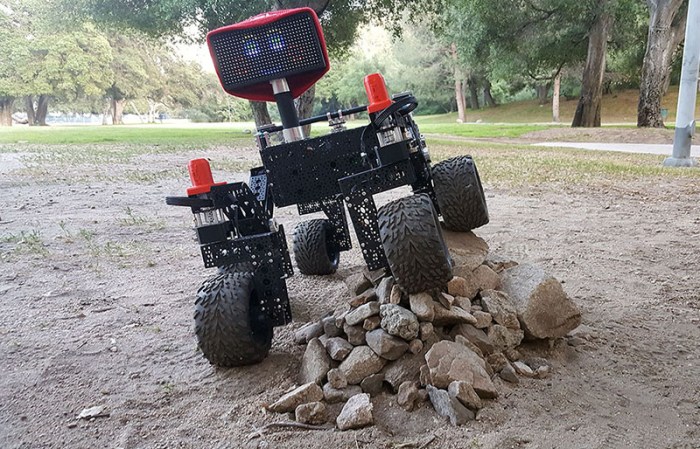
Back in January of this year I joined a team of pre-release beta testers for a project out of nearby Jet Propulsion Laboratory (JPL). While not exactly a state secret, we were asked not to overtly broadcast or advertise the project until after JPL’s own publicity office started doing so. This publicity release happened two days ago so the JPL Open Source Rover is now officially public.

Our team members drew from SGVHAK, so we’ve been calling our rover SGVHAK rover instead of JPL open source rover. Past blog entries talking about SGVHAK’s customization were described as done in contrast to a vague undefined “baseline rover.” I’ve gone back and edited those references (well, at least the ones I could find) to point to JPL’s rover web site. Which had gone live a few weeks ago but that was a “soft opening” until JPL’s publicity office made everything officially public.

After SGVHAK team completed the rover beta build in March, I went off on my own to build Sawppy the Rover as a much more affordable alternative to a rover model. To hit that $500 price point, I had described the changes and trade-offs against SGVHAK rover but it was really against JPL’s open source rover. I’ve fixed up these old blog posts minimally – the references are now correct though some of the sentence structures got a little awkward.

As part of JPL’s open source rover project, they had established a public web forum where people can post information about their builds. To share our story I’ve gone ahead and created a forum thread for SGVHAK rover, and a separate one for Sawppy.

I look forward to seeing what other people will build.

Bart the Robot Spins His Wheels

The initial test session with Bart the robot was a bust. But after reviewing the manual, we realized that a few jumpers needed to be set. These jumpers mark a control board as the end of the daisy-chain, and the end unit is where the NMC protocol’s roll-call procedure started. Bart probably had a few other NMC modules in his prime, and one of them would have been the end because neither of the current-day modules were configured as such. Since neither knew to act as the end unit, there was no module to respond to the start of the roll-call procedure, and NMC communication fails.

Once we marked our current-day motor control module as the end of the chain, the NMC roll-call was successful and our NMC test program was able to communicate with the boards. We were able to obtain readings from the encoder, and see it respond as we rotated the wheels by hand. That got us excited, and the first few motor commands we sent resulted in motor movement which got us even more excited.

Sadly, that initial enthusiasm was dampened by further experimentation. We tried to understand how the motor commands translated to actual motor movement but our experimentation returned very confusing results. The motors would work well on one move, and when we tweaked what we thought was a single small variable, it does something completely and unpredictably different.

Eventually we fell back to sending the same command over and over, and confirmed that the controller does not do the same thing in response. Same command sent repeatedly would result in wildly different speeds each time. Sometimes it even tries to spin the motor in the opposite direction resulting in an error condition and reset.

And every time we experienced a reset, the board would not consistently reconnect to the computer software. We would frequently have to disconnect and power cycle everything before we could resume experimentation.

Our hypothesis is that these control boards were left on Bart – and not salvaged for his successor – because they were malfunctioning. It’s just as likely something on the board degraded in the past 17 years. Either way, an unpredictable motor control board won’t do Bart any good. These closed-loop motor controllers would have been fantastic if we could get them running, so it was worth a bit of time and money to try them out. But now that we have our answer, it’s time to leave them behind.

Trying to Talk To Bart the Robot

The motivation to learn about stepper motors came from Bart the robot. The previous owners had pretty much cleaned out Bart components, but the locomotion subsystem is mostly intact. This consists of two wheel assemblies, each of which is driven by a beefy-looking stepper motor with a quadrature encoder attached to the other end of the shaft. This assembly is attached to a control board of some sort, implying closed-loop control. The board looks superficially intact so the obvious first step is to see if we can make them run.

The control board is made by J.R.Kerr LLC, a company that has since been acquired, but apparently there’s some sort of tech support obligation still in effect. Contacting the new owners confirmed the product is long out of production and no longer on the actively supported product list, but they suggested we look at documentation one of its still-supported relatives “PIC-SERVO 3PH” to get a rough idea. From such documentation we learned the product line communicate to each other via a protocol called “NMC” over RS-485 hardware. The official adapter “SSA-485” costs more than what we’d want to spend just for exploration, but there are vendors on Amazon selling RS-485 adapter (*) for impulse-buy money.

The adapter takes care of the hardware. For the software, a NMC Test Utility was available from the software downloads page. As the only person with a Windows machine, my laptop was roped into test duty.

The first exploration session was a failure – there was no response from the control boards at all. But there were no smoke and no fire, which is good. Probing the board confirmed components were receiving power, but there was no communication and certainly no motor motion. Thankfully, the second session was more successful.


(*) Disclosure: As an Amazon Associate I earn from qualifying purchases.

Embedding an Instagram Post with BBCode Without Plugin

UPDATE: The media retrieval endpoint described below is no longer supported after October 24, 2020. See developer documentation here for details on how to migrate to a replacement endpoint. Thanks [Andrew].


Embedding an Instagram post is trivial on a WordPress blog like this one: copy the full Instagram URL (like https://www.instagram.com/p/BfryG0VnUmF/) and paste it into the visual editor window. Behind the scenes, that URL is parsed to create an embed as shown here.

There are similar plugins to add an tag to a BBCode-based web forum. But what if a forum does not have such direct support installed? This was the case for the web forum set up as community driven support for JPL’s Open Source Rover.

On every Instagram post, there’s an “Embed” option that will bring up a chunk of HTML (which links to some JavaScript) to create an embed. However, a BBCode based web forum does not allow embedding arbitrary HTML like that.

Time to read the manual which in this case is Instagram’s developer resources page about embedding. They prefer that people use the fancy methods like that chunk of HTML we can’t use. But way down towards the bottom, they do describe how to use the /media/ endpoint to pull down just an image file with no active components.

Instagram Rover L

This is simple enough to use within the BBCode [IMG] tag. Then we can surround that image tag with a [URL] tag to turn it into a link to the Instagram post.

[URL=https://www.instagram.com/p/BfryG0VnUmF/][IMG]https://instagram.com/p/BfryG0VnUmF/media/?size=m[/IMG][/URL]

It’s not as fancy as the full embed code, but it does get the basic point across and provides an easy way to access the original Instagram post. Good enough for a SGVHAK Rover post on the JPL OSR web forum.

Github Seems To Have Stopped Showing STL Changes

A few years ago Github courted the 3D printing crowd by offering a 3D model viewer to see STL files, and then added a feature to visualize differences between revisions of STL files.

039e6170-1c8b-11e3-8020-b3157840fcf6

One of the reasons I put Sawppy STLs on Github is for people to see parts in their browser without having to install any software. I thought it would also be cool for people to see parts as they evolved. When I first started playing with putting STL files on Github, I thought this was a great way to track changes across major revisions.

Unfortunately, the revision visualization module seems to be gone. The 3D model viewer is still there so the primary motivation for putting STLs on Github is still good. But when I try to view file changes, the changes are no longer shown. The official help documentation still talks about the feature, it just doesn’t seem to work.

I liked seeing STL diffs visually and it makes me sad the feature is now inaccessible.

Road to Sawppy is Paved with Plastic

Today our Sawppy storyline on this blog has caught up to Sawppy version 1.0. The mechanical design for the six-wheel chassis has matured enough that it is a sufficiently functional platform for future projects. We still have mechanical tasks to do ahead of us: the camera mast still needs work, and Sawppy needs a robot arm like the real rovers. But the mechanical work will take a pause, so refinements in electrical design and software can catch up.

As part of declaring version 1.0, the assembly process has been documented on Github in the hopes that other people will build their own Sawppy. I know there’s interest but I don’t know how that interest will translate into action. It would be very rewarding for me to see other rovers running around.

The version 1.0 milestone also marks a time for housecleaning. I had been keeping all iterations of parts I’ve designed and printed on this project in a big bucket of fail. This is occasionally useful when I need to refer back to what I did for comparison to see if I’m actually improving the design. It was also useful to dig up for illustrating various posts on this blog as I tell Sawppy’s story. Now that I’ve completed documentation on Github and told the story of Sawppy evolution on this blog, it’s time to discard them.

But before we do that, a big group picture of all the retired parts with Sawppy the Rover version 1.0.


Sawppy the Rover Receives WiFi Upgrade, Increases Range

Sawppy is now back up and running with all its 3D printed parts recreated in MatterHackers PETG plastic. While the pieces could be replaced piecemeal, I decided to take everything apart and reassemble the whole thing so I could take pictures along the way and document the assembly process. Since I was basically rebuilding the rover from scratch anyway, I performed another upgrade: the compact Netgear WiFi router previously installed has been replaced with larger dual-band unit, the Asus RT-AC1200. Test drives have proven the new router gives Sawppy significantly more range!

Sawppy can now rove a decent distance from its handler. Far enough that it’s no longer easy to see exactly which way the rover is pointed, and we need to occasionally refer to Sawppy’s on-board camera video feed to see what’s going on. In the picture below, John is holding his phone showing the video feed while Emily is on the driving controls. This picture was taken as Emily drove Sawppy back towards us. In the relatively quiet RF environment of this industrial park, Sawppy can drive about three times further away than the distance shown in the picture before wireless communication suffers occasional data dropouts.

This range test proved that Sawppy can get far enough away that driving it around becomes a team activity: one to monitor the situation and another on the controls. This is more than enough range for most of our purposes.

What’s still unknown is Sawppy’s tolerance of noisy RF environments. That test will come, eventually…

Sawppy Pilots

Reclaiming Bearings From 3D Printed Parts: Round 2

Now that PETG is up and running smoothly on my printer, it was put to work reprinting all Sawppy parts so I could replace the existing PLA parts with PETG parts. Retiring parts means throwing away things like heat-set inserts, but the bearings could be recovered. I originally designed a few holes into the parts to make bearing removal easier, but I’ve since realized those holes are unnecessary. Plastic — both PLA and PETG — are soft enough for the bearings to flex and move inside their assigned positions. This flex allows us to work bearings loose by twisting a shaft inside the bearing.

Bearing Extraction

I tried describing this with words but my vocabulary really isn’t up to the task. Here’s a video to illustrate the technique.

This works well enough I think those bearing removal assist holes I added before are now unnecessary. I’ll probably remove the holes on my next revision of rover parts so it looks less like a piece of Swiss cheese.

Problems Printing PETG With Monoprice Maker Select (Wanhao Duplicator i3)

The first experiment in PETG was printing a servo coupler. It was small, printed at 0.1mm layer height. After the success of that initial experiment, I set the printer to work on a Sawppy rover wheel overnight at 0.3mm layer height. It did not turn out well.

First Complex PETG

Little bits of extraneous PETG strings all over the place! Stringing is usually credited to poor retraction settings, but that’s not the whole story here. Once this print gets above the first 20mm and no longer printing the center hub, it no longer performs any retracts – the wheel is printed in a continuous motion without retracts.

What these strings actually demonstrate is not poor retraction, but very poor layer adhesion. As the print head circles the perimeter laying down filament, it’s not all sticking and instead dragging along little bits of PETG causing these strings. It’s not very visible from this camera angle, but there are visible gaps between layers. And the layers came apart with only minor physical handling.

The layers came apart more easily in the middle sections. This was puzzling – what problem would be worse in the middle of the night but magically recover by morning? The answer: ambient air temperature. Apparently PETG needs more time than PLA to properly bond with the previous layer, and when cooled too quickly it won’t bond. I can’t change the weather on command, but I could turn off the print cooling fan.

Turning off print cooling helped somewhat, but it was not the whole solution. PETG melts less easily than PLA, which is a desired feature when it comes to rover parts that don’t deform under heat. But that attribute also creates printing headaches. The 0.1mm layer height print bonded well but the 0.3mm print did not, leading to the hypothesis that the print nozzle couldn’t melt PETG fast enough to deliver triple the volume of plastic.

To test this hypothesis, the print speed was cut to 1/3 of previous speed. The test object worked well, but this print speed is not acceptable. It would turn a rover wheel from an 8-hour print project to an all-day 24 hour print!

Another test is to turn up the heat on the nozzle, hopefully a hotter nozzle will melt PETG more quickly. This worked… briefly. It got too hot for the liner and it deformed, jamming the print path.

Damaged PTFE liner

The liner was original so perhaps it was just time for a replacement anyway. But when the replacement liner also jammed up within a few prints, I knew this was not going to work.

Given these data points, the hypothesis of “hot end couldn’t melt PETG fast enough” has merit. We know slowing down works, but is unacceptably slow. We know heating up works, until the liner quits.

I was not willing to accept the slowdown, so the alternative is to upgrade the hardware.