Notes on “ROS Robot Programming” Book by Creators of TurtleBot 3

ROS Robot Programming cover 800The people at Robotis who created TurtleBot 3 created a pretty good online manual for their robot that also served as a decent guide for a beginner like myself to start experimenting with ROS. But that’s not the only resource they’re released to the public – they’ve also applied themselves to writing a book. It has a straightforward title “ROS Robot Programming” and is described to be a compilation of what they’ve learned on their journey to create the TurtleBot 3. Pointers to the book are sprinkled throughout the TurtleBot 3 manual, most explicitly under the “Learn” section with additional resources.

The book is available in four languages: English, Chinese, Japanese, and Korean. The English and Chinese editions are also available freely as PDF. I thought I’d invest some time into reading the book, here are my comments:

Chapters 1-7: ROS Fundmentals

The reader is assumed to be a computer user who is familiar with general programming concepts, but no robotics knowledge is assumed. The book starts with the basic ideas behind ROS, then working from there. These chapters have a great deal of overlap with existing “Beginner Level” tutorials on ROS Wiki. Given this, I believe the bigger value of this book is in its non-English editions. Chinese/Japanese/Korean readers would probably benefit more from these sections written in their respective languages, making this information accessible for readers who can’t just go to the English ROS Wiki tutorials like I did.

Content-wise, the biggest deviation I found in this book was that it treated the action library as peers of ROS topics and services. As a user I agree it made sense to cover them together and I’m glad this book did it. And as someone who has worked on programming platforms, I understand why the official documentation treated them differently.

Chapter 8: Sensors and Motors

Given that chapters 1-7 overlapped a lot with the tutorials I’ve already covered, it was not terribly informative. That changed when I got into chapter 8, where we started talking about a few different classes of sensors people have used in ROS. When it came to motors, though, the only one covered was Robotis’ own Dynamixel product. This was a little disappointing – they could have at least put some minor lip service to motors other than their own product. But they chose not to.

This chapter ended with a useful tutorial and some words of wisdom about how to navigate the big library of ROS modules openly available for us to play with. This is a good place for the topic, because sensor and motor driver libraries are going to be the first things beginners have to deal with beyond core ROS modules. And skills dealing with these libraries will be useful for other things beyond sensors and motors.

Chapter 9-13: All Robotis All The Time

The rest of the book is effectively an extension of the TurtleBot 3 manual with side trips to other Robotis projects. They go over many of the same ideas, using their robots as example. But while the manual focused on a specific robot, the book did try to go a little deeper. They said their goal is to cover enough so the reader can adapt the same general ideas to other robots, but I don’t feel I’ve received quite enough information. This is only a gut feeling – I won’t know for sure until I start rolling up my sleeves and get to work on a real robot.

The final few chapters felt rushed. Especially the abrupt ending of the final manipulator chapter. Perhaps they will work to fill in some of the gaps in a future edition.

Final Verdict: B+

I felt like my time spent reading the PDF was well spent. If nothing else, I have a much better understanding of how TurtleBot 3 (and friends) work. The most valuable aspect was seeing ROS described from a different perspective. I plan to check out a few other ROS books from the library in the future, and after I get a few books under my belt I’ll have a better idea how “ROS Robot Programming” ranks among them. It’s clear the first edition has  room for improvement, but it is still useful.

Observations From A Neato LIDAR On The Move

Now that the laser distance scanner has been built into a little standalone unit, it’s easy to take it to different situations and learn how it reacts by watching RViz plot its output data. First I just picked it up and walked around the house with it, which led to the following observations:

  • The sensor dome sweeps in a full circle roughly four times per second. (240 RPM) This sounded pretty good at first, but once I started moving the sensor it doesn’t look nearly as good. Laser distance plot is distorted because it’s moving while it’s sweeping, visibly so even at normal human walking speeds. Clearly a robot using this unit will have to post-process distance data generated by this sensor to compensate for speed. Either that, or just move really slowly like the Neato XV-11 robot vacuum this LIDAR was salvaged from.
  • The distance data is generated from a single narrowly focused beam. This generates detailed sweep data at roughly one reading per vertical degree of separation. However, it also means we’re reading just a very narrow one degree horizontal slice of the environment. It’s no surprise this is limiting, but just how limited wasn’t apparent until we started trying to correlate various distance readings with things we can see with our eyes.

Autonomous vehicles use laser scanners that spin far faster than this one, and they use arrays of lasers to scan multiple angles instead of just a single horizontal beam. First hand experimentation with this inexpensive unit really hammered home why those expensive sensors are necessary.

Neato LIDAR on SGVHAK Rover

After the few handheld tests, the portable test unit was placed on top of SGVHAK Rover and driven around a SGVHAK workshop. There’s no integration at all…. not power, not structure, and certainly not data. This was just a quick smoke test that was very productive because it lead to more observations:

  • Normal household wall paint, especially matte or eggshell, works best. This is not a surprise given that it was designed to work on a home vacuum robot.
  • Thin structural pieces of shelving units are difficult to pick up.
  • Shiny surfaces like glass become invisible – presumably the emitted beam is reflected elsewhere and not back into the detector. Surprisingly, a laptop screen with anti-reflective matte finish behaved identically to shiny glass.
  • There’s a minimum distance of roughly 15-20cm. Any closer and laser beam emitted is reflected too early for detector to pick up.
  • Maximum range is over 4-5 meters (with caveat below). More than far enough for a vacuum robot’s needs.

The final observation was unexpected but obvious in hindsight: The detection capability is affected by the strongest returns. When we put a shiny antistatic bag in view of the sensor, there was a huge distortion in data output. The bag reflected laser back to the scanner so brightly that the control electronics reduced receiver sensitivity, similar to how our pupils contract in bright daylight. When this happens, the sensor could no longer see less reflective surfaces even if they were relatively close.

That was fun and very interesting set of experiments! But now it’s time to stick my head back into my ROS education so I can make use of this laser distance sensor.

Making My Neato LIDAR Mobile Again

The laser distance sensor I bought off eBay successfully managed to send data to my desktop computer, and the data looks vaguely reasonable. However, I’m not interested in a static scanner – I’m interested in using this on a robot that moves. Since I don’t have the rest of the robot vacuum, what’s the quickest way I can hack up something to see how this LIDAR unit from a Neato XV-11 works in motion?

Obviously something on the move needs to run off battery, and there’s already a motor voltage regulator working to keep motor speed correct. So that part’s easy, and attention turns to the data connection. I needed something that can talk to a serial device and send that data wirelessly to my computer. There are many ways to do this in the ROS ecosystem, but in the interest of time I thought I’d just do it in the way I already know how. A Raspberry Pi is a ROS-capable battery-powered computer and everything I just did on my computer would work on a Pi. (The one in the picture here has the Adafruit servo control PWM HAT on board, though the HAT is unused in this test.)

Mobile Scanning Module

The Raspberry Pi is powered by its own battery voltage regulator I created for Sawppy, supplying 5 volts and running in parallel with an identical unit tuned for 3 volts supplying power to spin the motor. As always, the tedious part is getting a Pi on the wireless network. But once I could SSH into the Pi wirelessly, I could run all the ROS commands I used on my desktop to turn this into a mobile distance data station. Reading in data via FTDI serial port adapter, sends data out as ROS topic /scan over WiFi.

Using a Raspberry Pi 3 in this capacity is complete overkill – the Pi 3 can easily shuttle 115200 bps serial data over the network. But it was quick to get up and running. Also – the FTDI is technically unnecessary because a Pi has 3.3V serial capability on board that we could use. It’s not worth the time to fuss with right now but something to keep in mind for later.

Now that the laser is mobile, it’s time to explore its behavior on the move…

Telling USB Serial Ports Apart with udev Rules

Old school serial bus is great for robot hacking. It’s easy and widespread in the world of simple microcontrollers, and it’s easy for a computer to join in the fun with a USB to serial adapter. In my robot adventures so far, it’s been used to talk to Roboclaw motor controllers, to serial bus servos, and now to laser distance scanners. But so far I’ve only dealt with one of them at any given time. If I want to build a sophisticated robot with more than one of these devices attached, how do I tell them apart?

When dealing with one device at a time, there is no ambiguity. We just point our code to  /dev/ttyUSB0 and get on with our experiments. But when we have multiple devices, we’ll start picking up /dev/ttyUSB1, /dev/ttyUSB2, etc. And even worse, there is no guarantee on their relative order. We might have the laser scanner on /dev/ttyUSB2, and upon computer reboot, the serial port associated with laser scanner may become /dev/ttyUSB0.

I had vague idea that a Linux mechanism called ‘udev rules‘ can help with this problem, but most of the documentation I found were written for USB device manufacturers. They can create their own rules corresponding to their particular vendor and product identification, and create nice-sounding device names. But I’m not a device manufacturer – I’m just a user of USB to serial adapters, most of which use chips from a company called FTDI and will all have the same vendor and product ID.

The key insight came in as a footnote of the XV-11 ROS node instructions page: it is possible to create udev rules that create a new name incorporating a FTDI chip’s unique serial number.

echo 'SUBSYSTEMS=="usb", KERNEL=="ttyUSB[0-9]*", ATTRS{idVendor}=="0403", ATTRS{idProduct}=="6001", SYMLINK+="sensors/ftdi_%s{serial}"' > /etc/udev/rules.d/52-ftdi.rules

Such a rule results in a symbolic link that differentiates individual serial devices not by an arbitrary and changing order, but a distinct and unchanging serial number.

In the screenshot, my serial port is visible as /dev/ttyUSB0… but it is also accessible as /dev/sensors/ftdi_AO002W1A. By targeting my code to the latter, I can be sure they’ll be talking on the correct port. No matter which USB port it was plugged into, or what order the operating system enumerated those devices. I just need to put in the one-time upfront work to write down which serial number corresponds to which devices, code that into my robot configuration, and all should be well from there.

This mechanism solves the problem if I use exclusively USB-to-serial adapters built from FTDI chips with unique serial numbers. Unfortunately, sometimes I have to use something else… like the LewanSoul serial bus servo interface board (*). It uses the CH341 chip for communication, and this chip does not have a unique serial number.

This isn’t a problem in the immediate future. One LewanSoul serial servo control board on can talk to all LewanSoul serial servos on the network. So as long as we don’t need anything else using the same CH341 chip (basically use FTDI adapters for everything else) we should be fine… or at least not worry about it until we have to cross that bridge.


(*) Disclosure: As an Amazon Associate I earn from qualifying purchases.

Shouldn’t Simple LIDAR Be Cheaper By Now?

While waiting on my 3D printer to print a simple base for my laser distance scanner salvaged from a Neato robot vacuum, I went online to read more about this contraption. The more I read about it, the more I’m puzzled by its price. Shouldn’t these simple geometry-based distance scanners be a lot cheaper by now?

The journey started with this Engadget review from 2010 when Neato’s XV-11 was first introduced to fanfare that I apparently missed at the time. The laser scanner was a critical product differentiation for Neato, separating them from market leader iRobot’s Roomba vacuums. It was an advantage that was easy to explain and easy for users to see in action on their product, both of which help to justify their price premium.

Of course the rest of its market responded and now high-end robot vacuums all have mapping capability of some sort or another, pushing Neato to introduce other features like internet connectivity and remote control via a phone app. In 2016 Ars Technica reviewed these new features and found them immature. But more interesting to my technical brain is that Ars linked to a paper on Neato’s laser scanner design. Presented at May 19-23 2008 IEEE International Conference on Robotics and Automation titled A Low-Cost Laser Distance Sensor and listing multiple people from Neato Robotics as authors, it gave an insight into these spinning domes. Including this picture of internals.

Revo LDS

But even more interesting than the fascinating technology outlined in the paper, is the suggested economics advantage. The big claim is right in the abstract:

The build cost of this device, using COTS electronics and custom mechanical tooling, is under $30.

Considering that Neato robot vacuums have been in mass production for almost ten years, and that there’s been ample time for clones and imitators to come on market, it’s quite odd how these devices still cost significantly more than $30. If the claim in the paper is true, we should have these types of sensor for a few bucks by now, not $180 for an entry-level unit. If they were actually $20-$30, it would make ROS far more accessible. So what happened on the path to cheap laser scanner for everyone?

It’s also interesting that some other robot vacuum makers – like iRobot themselves – have implemented mapping via other means. Or at least, there’s no obvious dome of a laser scanner on top of some mapping-capable Neato competitors. What are they using, and are similar techniques available as ROS components? I hope to come across some answers in the near future.

Simple Base for Neato Vacuum LIDAR

Since it was bought off eBay, there was an obvious question mark associated with the laser scanner salvaged from a Neato robot vacuum. But, following instructions on ROS Wiki for a Neato XV-11 scanner, results of preliminary tests look very promising. Before proceeding to further tests, though, I need to do something about how awkward the whole thing is.

The most obvious problem are the two dangling wires – one to supply motor power and one to power and communicate with the laser assembly. I’ve done the usual diligence to reduce risk of electrical shorts, but leaving these wires waving in the open will inevitably catch on something and break wires. The less obvious problem is the fact this assembly does not have a flat bottom, the rotation motor juts out beyond the remainder of the assembly preventing the assembly from sitting nicely on a flat surface.

So before proceeding further, a simple base is designed and 3D-printed, using the same four mounting holes on the laser platform designed to bolt it into its robot vacuum chassis. The first draft is nothing fancy – a caliper was used to measure relative distance between holes. Each mounting hole will match up to a post, whose height is dictated by thickness of rotation motor. A 5mm tall base connects all four posts. This simple file is a public document on Onshape if anyone else needs it.

Each dangling wire has an associated circuit board – the motor power wire has a voltage regulator module, and the laser wire has a 3.3V capable USB to serial bridge (*). Keeping this first draft simple, circuit boards were just held on by double-sided tape. And it’s a good thing there wasn’t much expectation for the rough draft as even the 3D printer had a few extrusion problems during the print. But it’s OK to be rough for now. Once we verify the laser scanner actually works for robot project purposes, we’ll put time into a nicer mount.

Simple Neato LDS base
Bottom view of everything installed on simple 3D printed base.

(*) Disclosure: As an Amazon Associate I earn from qualifying purchases.

Neato Vacuum Laser Scanner Works in RViz

Scanner Motor Spins
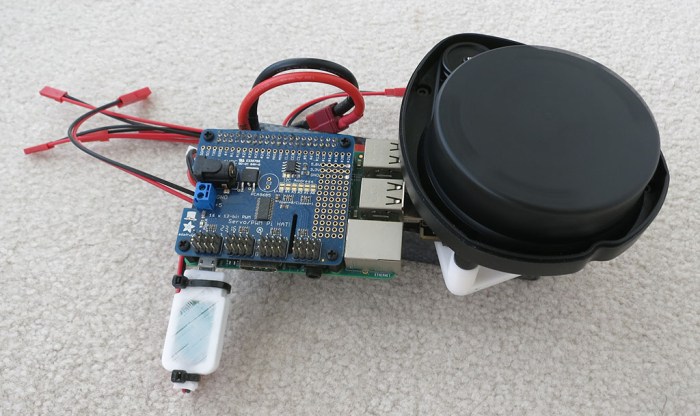
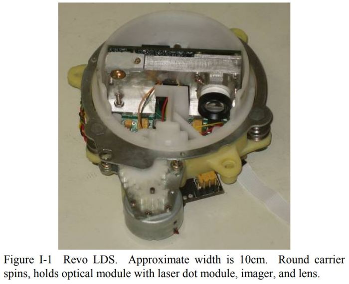
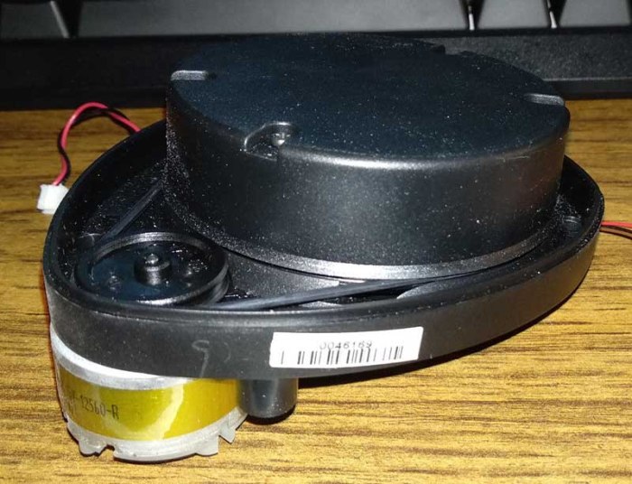
I bought a laser scanner salvaged from a Neato robot vacuum off eBay. The promised delivery date is mid next week but the device showed up far earlier than anticipated. Which motivated me to drop other projects and check out the new toy immediately.

The first test is to verify the rotation motor works. According to instructions, it demands 3.0 volts which I dialed up via my bench power supply. Happily, the scanner turns. After this basic verification, I took one of the adjustable voltage regulators I bought to power a Raspberry Pi and dialed it down to an output of 3.0 volts. Since the connectors have a 2mm pitch, my bag of 4-pin JST-XH connectors could be persuaded to fit. It even looks like the proper connector type, though the motor connector only uses two pins out of four.

The instructions also had data pinout, making it straightforward to solder up an adapter to go between it and a 3.3V capable USB serial adapter. This particular adapter (*) claims to supply 3.3V between 100-200mA. Since the instruction said the peak power draw is around 120mA, it should be OK to power the laser directly off this particular USB serial adapter.

Scanner Power and Data

With physical connection complete, it’s time to move on to the software side. This particular XV-11 ROS node is available in both binary and source code form. I chose to clone the Github source code because I have ambition to go in and read the source code later. The source code compiled cleanly and RViz, the data visualizer for ROS data, was able to parse laser data successfully.

That was an amazingly smooth and trouble-free project. I’m encouraged by the progress so far. I hope we could incorporate this into a robot and, if it proves successful, I anticipate buying more of these laser sensors off eBay in the future.


(*) Disclosure: As an Amazon Associate I earn from qualifying purchases.

Incoming: Neato Robot Vacuum Laser Scanner

The biggest argument against buying a Monoprice robot vacuum for ROS hacking is that I already know how to build a two-wheeled robot chassis. In fact two-wheeled differential drive is a great simple test configuration that I’ve done once or twice. Granted, I have yet to build either of them into having full odometry capability, but I do not expect that to be a fundamentally difficult thing.

No, the bigger challenge is integrating sensing into a robot. Everything I’ve built so far has no smarts – they’re basically just big remote-control cars. The ambition is to ramp up on intelligent robots and that means giving a robot some sense of the world. The TurtleBot 3 Burger reads its surroundings with a laser distance sensor that costs $180. It’s been a debate whether I should buy one or not.

But at this past Monday’s SGVHAK meetup, I was alerted to the fact that some home robot vacuums use a laser scanner to map their surroundings for use planning more efficient vacuum patterns. I knew home robot vacuums have evolved beyond the random walk vacuum pattern of the original Roomba, but I didn’t know their sophistication has evolved to incorporate laser scanners. Certainly neither of the robot vacuums on clearance at Monoprice have a laser scanner.

But there are robot vacuums with laser scanners and, more importantly, some of these scanner-equipped robot vacuums are getting old enough to break down and stop working, resulting in scavenged components being listed on eBay… including their laser scanner! Items come and go, but I found this scavenged scanner for $54 and clicked “Buy It Now”. The listing claims it works, but it’s eBay… we’ll find out for sure when it arrives. But even if it doesn’t, Neato vacuums are available nearby for roughly the same price, so I have the opportunity for multiple attempts.

The unit off eBay was purportedly from a Neato XV-11 vacuum and someone in the ROS community has already written a package to interface with the sensor. The tutorials section of this package describes how to wire it up electrically. It looks fairly straightforward and I hope it’ll all come together as simply as I hope it will when the eBay item arrives in about a week and a half.

Neato Scanner 800


Monoprice Vacuums Are Tempting For Robot Hacking

The original research hardware for ROS is the Willows Garage PR2, a very expensive robot. To make ROS accessible to people with thinner wallets, the TurtleBot line was created. The original TurtleBot was based on the iRobot Create, a hacking-friendly variant of their Roomba home robot vacuum. Even then, the “low-cost” robot was still several thousand dollars.

The market has advanced in that time. TurtleBot 3 has evolved beyond a robot vacuum base, and the iRobot Create 2 itself is available for $200. Not exactly pocket change but far more accessible. The market pioneered by Roomba is also no longer dominated by iRobot, with lots of competitors, which brings us to cheap Chinese clones. Some of which are sold by Monoprice, and right now, it seems like Monoprice is either abandoning the market or preparing for new products – their robot vacuums are on clearance sale presenting tempting targets for robotic hacking.

Monoprice Cadet 512
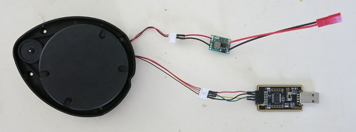
The low-end option is the “Cadet“, and looking at the manual we see its basic two-wheel differential drive mechanism is augmented by three cliff sensors in addition to the bump sensors. The hardware within only has to support the basic random walk pattern, so the expectation is not high. But that might be fine at its clearance sale price of $55.

Monoprice Intelligent Vacuum 512The higher-end option is the “Intelligent Vacuum“. It has a lot more features, some of which are relevant for the purposes of robot hacking. It still has all the cliff sensors, but it also has a few of those proximity sensors pointing outwards to augment the bump sensors. But most interesting to robot hacking – it is advertised to vacuum in one of several patterns and not just random walk. This implies wheel encoders or something to track robot movement. There’s also a charging base docking station that the robot can return to charge, backing up the speculation there exists mechanisms on board the robot for odometry. Its clearance sale price of $115 is not significantly higher than the cost of building a two-wheeled robot with encoder, plus its own battery, charger, and all the sensors.

As tempting as they are, though, I think I’ll go down a different path…

HTML with Bootstrap Control Interface for ROSBot

While learning ROS, I was confident that it would be possible to replicate the kind of functionality I had built for SGVHAK rover. That is to say: putting up a HTML-based user interface for the user and talking to robot mechanical based on user input. Except that, in theory, the modular nature of ROS and its software support should mean it’ll take less time to build one. Or at least, it should be for someone who had already invested in the learning curve of ROS infrastructure.

At the time I didn’t know how long it would take to ramp up on ROS. I’m also a believer that it is educational to do something the hard way once to learn the ropes. So SGVHAK Rover received a pretty simple robot control built from minimal use of frameworks. Now that I’m ramping up on ROS, I’m debating whether it’s worthwhile to duplicate the functionality for self-education’s sake or if I want to go straight to something more functional than a remote control car.

This week I have confirmation a ROS web interface pretty simple to do: this recent post on Medium described one way of creating a web-based interface for a ROS robot. The web UI framework used in this tutorial is Bootstrap, and the sample robot is ROSBot. The choice of robot is no surprise since the Medium post was written by CEO of Husarion, maker of the robot. At MSRP of $1,299 it is quite a bit out of my budget for my own ROS experimentation at least for now. Still, the information on Medium may be useful if I tackle this project myself for a different robot, possibly SGVHAK rover or Sawppy.

Processed by: Helicon Filter;


New Addition To ROS: Bridge To OpenAI

OpenAI LogoWhile we’re on the topic of things I wanted to investigate in the future… there was a recent announcement declaring availability of the openai_ros package, a ROS toolkit to connect OpenAI to robots running ROS. Like the Robotis demo on how to use TensorFlow in ROS, it reinforces that ROS is a great platform for putting these new waves of artificial intelligence tools into action on real robots. Of course, that assumes I’ve put in the time to become proficient with these AI platforms and that has yet to happen. Like TensorFlow, learning about OpenAI is still on my to-do list and most of the announcement information didn’t mean anything to me. I understood the parts talking about Gazebo and about actual robot, but the concept of an OpenAI “task” is still fuzzy, as are details on how it relates to OpenAI training.

What’s clear is that my to-do list is growing faster than I can get through them. This is not a terrible problem to have, as long as it’s all interesting and rewarding to learn. But I can only take so much book learning before I lose my anchor and start drifting. Sometime soon I’ll have to decide to stop with the endless reading and put in some hands-on time to make abstract ideas concrete.

It’ll be fun when I get there, though. OpenAI recently got some press with their work evolving a robotic hand to perform dexterous manipulations of a cube. It looks really slick and I look forward to putting OpenAI to work on my own projects in the future.

New Addition To TurtleBot 3 Manual: TensorFlow

TensorFlow LogoBeing on the leading edge carries its own kind of thrill. When I started looking over the TurtleBot 3 manual I noticed the index listed a “Machine Learning” chapter. As I read through all the sections in order, I was looking forward to that chapter. Sadly I was greatly disappointed when I reached that chapter and saw it was a placeholder with “Coming Soon!”

I didn’t know how soon that “soon” was going to be, but I did not expect it to be a matter of days. But when I went back to flip through the material today I was surprised to see it’s no longer a placeholder. The chapter got some minimal content within the past few days, as confirmed by Github history of that page. Nice! This is definitely a strength of an online electronic manual versus a printed one.

So it’s no longer “Coming Soon!” but it is also by no means complete. Or at least, the user is already assumed to understand machine learning via DQN algorithms. Since I put off my own TensorFlow explorations to look at ROS, I have no idea what that means or how I might tweak the parameters to improve results. This page looks especially barren when compared to the mapping section, where the manual had far more information on how the algorithm’s parameters can be modified.

Maybe they have plans to return a flesh it out some more in the future, which would be helpful. Alternatively, it’s possible that once I put some time into learning TensorFlow I will know exactly what’s going on with this page. But right now that’s not the case.

Still, it’s encouraging to know that there are documented ways to use TensorFlow machine learning algorithms in the context of driving a robot via ROS. I look forward to the day when I know enough to compose all these pieces together to build intelligent robots.

TurtleBot3 Demo Navigating Gazebo Simulation World

Continuing on this beginner’s exploration of ROS, I got a taste of how a robot can be more intelligent about its movement than the random walk of turtlebot3_drive. It also gave me a taste of how much I still have to learn about how to effectively use all these open source algorithms available through the ROS ecosystem, but seeing these things work is great motivation to put in the time to learn.

There’s an entire chapter in the manual dedicated to navigation. It is focused on real robots but it only needs minimal modification to run in simulation. The first and most obvious step is to launch the “turtle world” simulation environment.

roslaunch turtlebot3_gazebo turtlebot3_world.launch

Then we can launch the navigation module, referencing the map we created earlier.

roslaunch turtlebot3_navigation turtlebot3_navigation.launch map_file:=$HOME/map.yaml

When RVis launches, we see one and a half turtle world. The complete turtle world is the map data, the incomplete turtle world is the laser distance data. We see the two separately because the robot doesn’t yet know where it is, resulting in a gross mismatch between map data and sensor data.

Navigation Startup

ROS navigation can determine the robot’s position, but it needs a little help with initial position. We provide this help by clicking on “2D Pose Estimate” and drawing an arrow. First we click on the robot’s position on the map, then we drag upwards to point the arrow up representing the direction our robot is facing.

navigation-pose_estimate.png

In theory, once the robot knows roughly where it is and which direction it is facing, it can match laser data up to the map data and align itself the rest of the way. In practice it seems like we need to be fairly precise about the initial pose information for things to line up.

Navigation Aligned

Once aligned, we can click on “2D Nav Goal” to tell our robot navigation routine where to go. The robot will then plan a route and traverse that route, avoiding obstacles along the way. During its travel, the robot will continuously evaluate its current position against the original plan, and adjust as needed.

Navigation Progress

That was a pretty cool demo!

Of course there’s a lot of information shown on RViz, representing many things I still need to sit down and learn in the future. Such as:

  • What are those little green arrows? They’re drawn in RVis under the category named “Amcl Particles” but I don’t know what they mean yet.
  • There’s a small square surrounding the robot showing a red-to-blue gradient. The red appears near obstacles and blue indicates no obstacles nearby. The RViz check box corresponding to this data is labelled “Costmap”. I’ll need to learn what “cost” means in this context and how it can be adjusted to suit different navigation goals.
  • What causes the robot to deviate off the plan? In the real world I would expect things like wheel slippage to cause a robot to veer off its planned path. I’m not sure if Gazebo helpfully throws in some random wheel slippage to simulate the real world, or if there are other factors at play causing path deviations.
  • Sometimes the robot happily traverses the route in reverse, sometimes it performs a three-point-turn or in-place turn before beginning its traversal. I’m curious what dictates the different behaviors.
  • And lastly: Why do we have to do mapping and navigation as two separate steps? It was a little disappointing this robot demo separates them, as I had thought state of the art is well past the point where we could do both simultaneously. There’s probably a good reason why this is a hard problem, I just don’t know it yet in my ignorance.

Lots to learn!

Running TurtleBot3 Mapping Demonstration (With a Twist)

We’ve found our way to the source code for the simple turtlebot3_drive node. It’s a simple starting point to explore writing code in ROS that’ll be worth returning to in the future. In the meantime I keep looking at the other fun stuff available in ROS… like making the robot a little bit smarter. Enter the TurtleBot SLAM (simultaneous location and mapping) demonstration outlined in the manual.

Like all of the TurtleBot3 demo code from the e-Manual, we start by launching the Gazebo simulation environment.

roslaunch turtlebot3_gazebo turtlebot3_world.launch

Then we can launch the node to run one of several different algorithms. Each have strengths and weaknesses, this one has the strength of “it’s what’s in the manual” for a starting point.

roslaunch turtlebot3_slam turtlebot3_slam.launch slam_methods:=gmapping

Note: If this node failed to launch with the error ERROR: cannot launch node of type [gmapping/slam_gmapping]: gmapping it means the required module has not been installed. Install (on Ubuntu) with sudo apt install ros-kinetic-slam-gmapping.

If successful, this will launch RViz and we can see the robot’s map drawn using what it can detect from its initial position.

Initial SLAM map

To fill out the rest of the map, our virtual TurtleBot needs to explore its space. The manual suggests running the ‘turtlebot3_teleop‘ module so we can use our keyboard to drive TurtleBot around turtle world. But I think it’s more fun to watch the robot map its own world, so let’s launch turtlebot3_drive instead.

roslaunch turtlebot3_gazebo turtlebot3_simulation.launch

Using this simple self-exploration mode the turtle world will be mapped out eventually. How long this will take depends on luck. One interesting observation is that there’s no explicit randomness in the turtlebot3_drive source code, but because the Gazebo simulation environment inserts randomness in the data to simulate unpredictability of real sensors, turtlebot3_drive ends up being a random walk.

Once our robot has completed mapping its world, we can save it for the navigation demo.

rosrun map_server map_saver -f ~/map

Final SLAM map

More details on how to tune SLAM algorithm parameters are in the SLAM chapter of the manual, which is mainly focused on running the real robot rather than simulation but most of the points still apply.

Understanding a Simple ROS Robot Control Program

In the previous post, a simple “Hello World” Gazebo robot simulation was parsed into its components. I was interested in the node named “turtlebot3_drive” and I’ve figured out how to go from the rqt_graph diagram shown yesterday to its source code.

  1. Decide the node /turtlebot3_drive was interesting.
  2. Look back at the command lines executed and determine it’s most likely launched from roslaunch turtlebot3_gazebo turtlebot3_simulation.launch
  3. Look at the launch file by running rosed turtlebot3_gazebo turtlebot3_simulation.launch
  4. Look through the XML file to find the node launch element <node name="$(arg name)_drive" pkg="turtlebot3_gazebo" type="turtlebot3_drive" required="true" output="screen"/>
  5. Go into the turtlebot3_gazebo package with roscd turtlebot3_gazebo
  6. Look at its makefile CMakeLists.txt
  7. See the executable turtlebot3_drive declared in the line add_executable(turtlebot3_drive src/turtlebot3_drive.cpp)
  8. Look at the source file rosed turtlebot3_gazebo turtlebot3_drive.cpp

Now we can look at the actual nuts and bolts of a simple ROS control program. I had hoped it would be pretty bare-bones and was happy to find that I was correct!

I had feared the laser rangefinder data parsing code would be super complicated, because the laser scanner looks all around the robot. As it turns out, this simple random walk only looks at distance in three directions: straight ahead (zero degrees), 30 degrees one way (30 degrees) and 30 degrees the other (330 degrees) inside the laser scanner data callback Turtlebot3Drive::laserScanMsgCallBack() This particular piece of logic would have worked just as well with three cheap individual distance sensors rather than the sophisticated laser scanner.

The main decision-making is in the GET_TB3_DIRECTION case of the switch statement inside Turtlebot3Drive::controlLoop(). It goes through three cases – if straight ahead is clear, proceed straight ahead. If there’s an obstacle near the right, turn left. And vice versa for right.

GET_TB3_DIRECTION

This is a great simple starting point for experimentation. We could edit this logic, go back to catkin root and run catkin_make, then see the new code in action inside Gazebo. This feels like the kind of thing I would write for competitions like RoboRodentia, where there’s a fixed scripted task for the robot to perform.

I could stay and play with this for a while, but honestly the motivation is not strong. The attraction of learning ROS is to buid on top of the work of others, and to play with recent advances in AI algorithms. Hand-coding robot logic would be an excellent exercise in using ROS framework but the result would not be novel or innovative.

Maybe I’ll have the patience to sit down and do my homework later, but for now, it’s off to chasing shiny objects elsewhere in the ROS ecosystem.

A Beginner’s Look Into The Mind of a Simulated ROS Robot

The previous post outlined a relatively minimal path to getting a virtual robot up and running in the Gazebo simulation environment. The robot is a virtual copy of the physical TurtleBot 3 Burger, and they both run code built on ROS. This setup should be pretty close to a ROS “Hello World” for a beginner like myself to get started poking at and learning what’s going on.

The first thing to do is to run rostopic list. As per tutorial on ROS topics, this is a tool to see all the information topics being published by all components running under a ROS core.

/clicked_point
/clock
/cmd_vel
/gazebo/link_states
/gazebo/model_states
/gazebo/parameter_descriptions
/gazebo/parameter_updates
/gazebo/set_link_state
/gazebo/set_model_state
/gazebo_gui/parameter_descriptions
/gazebo_gui/parameter_updates
/imu
/initialpose
/joint_states
/move_base_simple/goal
/odom
/rosout
/rosout_agg
/scan
/statistics
/tf
/tf_static

That’s a pretty long list of topics, which might seem intimidating at first glance until we realize just because it’s available doesn’t mean it’s being used.

How do we look at what’s actually in use? Again from the ROS topics tutorial, we can use a ROS utility that graphs out all active nodes and the topics they are using to talk to each other. rosrun rqt_graph rqt_graph

random walk rqt_graph.png

Ah, good. Only a few things are active. And this was only when we have everything running as listed at the end of the previous post, which were:

  1. TurtleBot in Gazebo
  2. TurtleBot performing a random walk with collision avoidance
  3. Rviz to plot laser range-finder data.

If we stop Rvis, the /robot_state_publisher node disappears, so that was used exclusively for visualization. The two nodes prefixed with gazebo are pretty obviously interface points to the simulator, leaving /turtlebot3_drive as the node corresponding to the random walk algorithm.

The velocity command topic /cmd_vel looks just like the one in the basic turtlesim used in the ROS tutorial, and I infer it is a standardized way to command robot movement in ROS components. The /scan topic must then be the laser rangefinder data used for collision avoidance.

To find the source code behind item #2, the obvious starting point is the command line used to start it: roslaunch turtlebot3_gazebo turtlebot3_simulation.launch. This tells us the code lives in the turtlebot3_gazebo module and we can look at the launch instructions by giving the same parameters to the ROS edit command. rosed turtlebot3_gazebo turtlebot3_simulation.launch. This brings up a XML file that described components for the random walk. From here I can see the node comes from something called “turtlebot3_drive“.

I found a turtlebot3_drive.cpp in the source code tree by brute force. I’m sure there was a better way to trace it from the .launch file to the .cpp, I just don’t know it yet. Maybe I’ll figure that out later, but for now I have a chunk of ROS C++ that I can tinker with.


ROS Notes: Gazebo Simulation of TurtleBot 3 Burger

TurtleBot 3 is the least expensive standard ROS introductory robot, and its creator Robotis has put online a fairly extensive electronic manual to help owners. The information is organized for its target audience, owners of the physical robot, so someone whose primary interest is simulation will have to dig through the manual to find the relevant bits. Here are the pieces I pulled out of the manual.

Operating System and ROS

Right now the target ROS distribution is Kinetic Kame, the easiest way is to have a computer running Ubuntu 16.04 (‘Xenial’) and follow ROS Kinetic instructions for a full desktop installation.

Additional Packages

After ROS is installed, additional packages are required to run a TurtleBot 3. Some of these, though probably not all, are required to run TB3 in simulation.

sudo apt-get install ros-kinetic-joy ros-kinetic-teleop-twist-joy ros-kinetic-teleop-twist-keyboard ros-kinetic-laser-proc ros-kinetic-rgbd-launch ros-kinetic-depthimage-to-laserscan ros-kinetic-rosserial-arduino ros-kinetic-rosserial-python ros-kinetic-rosserial-server ros-kinetic-rosserial-client ros-kinetic-rosserial-msgs ros-kinetic-amcl ros-kinetic-map-server ros-kinetic-move-base ros-kinetic-urdf ros-kinetic-xacro ros-kinetic-compressed-image-transport ros-kinetic-rqt-image-view ros-kinetic-gmapping ros-kinetic-navigation ros-kinetic-interactive-markers

TurtleBot 3 Code

The Catkin work environment will need to pull down a few Github repositories for code behind TurtleBot 3, plus one repo specific to simulation, then run catkin_make to build those pieces of source code.

$ cd ~/catkin_ws/src/
$ git clone https://github.com/ROBOTIS-GIT/turtlebot3_msgs.git
$ git clone https://github.com/ROBOTIS-GIT/turtlebot3.git
$ git clone https://github.com/ROBOTIS-GIT/turtlebot3_simulations.git
cd ~/catkin_ws && catkin_make

Simple Simulation

There are several simulations available in the manual’s “Simulation” chapter, here is my favorite. First: launch a Gazebo simulation with a TurtleBot 3 Burger inside the turtle-shaped test environment. At a ROS-enabled terminal, run

$ export TURTLEBOT3_MODEL=burger
$ roslaunch turtlebot3_gazebo turtlebot3_world.launch

(Note: If this is the first run of Gazebo, it will take several minutes to start. )

Once started, there will be a little virtual TurtleBot 3 Burger inside a turtle-shaped virtual room, sitting still and not doing anything. Which isn’t terribly interesting! But we can open a new ROS-enabled terminal to launch a very simple control program. This performs a random walk of the robot’s space, using the distance sensor to avoid walls.

$ export TURTLEBOT3_MODEL=burger
$ roslaunch turtlebot3_gazebo turtlebot3_simulation.launch

Turtle Room

Which is great, but I also want to see what the robot sees with its laser distance sensor. This information can be explored using Rvis, the data visualization tool built into ROS. Open up yet another ROS-enabled terminal to launch it.

$ export TURTLEBOT3_MODEL=burger
$ roslaunch turtlebot3_gazebo turtlebot3_gazebo_rviz.launch

This opens up an instance of Rvis, which will plot out the relative location of the robot and where it sees return pulses from its laser distance sensor.

Laser Rangefinder

ROS Notes: TurtleBot 3 Burger

Now that I have a very basic understanding of robotic simulation environment Gazebo, I circled back to ROS tutorial’s Where Next page. They suggested running virtual versions of one of two robots to learn about ROS: either a PR2 or a TurtleBot. I knew the PR2 is an expensive research-oriented robot that costs about as much as a Lamborghini, so whatever I build will be more along the lines of a TurtleBot. Sadly, the official TurtleBot’s idea of “low cost” is only relative to the six-figure PR2: when I last looked at ROS over a year ago, a TurtleBot 2 would still cost several thousand dollars.

Today I’m happy to learn that my information is out of date. When I last looked at ROS a year ago, the third generation of TurtleBot would have just launched and either it wasn’t yet publicly available or I just missed that information. Now there are two siblings in the far more affordable TurtleBot 3 family: the TurtleBot 3 Waffle is a larger robot suitable as platform for more elaborate projects, and the TurtleBot 3 Burger is a smaller robot with less room for expansion. While the Waffle is still over a thousand dollars, hobbyists without a kilobuck toy budget can consider the entry level TurtleBot 3 Burger.

Offered at $550, that price tag is within the ballpark of robot projects like my own Sawppy rover. If we look at the MSRP of its major components (OpenCR board + Raspberry Pi + IMU + laser scanner + 2 Dynamixel XL430 servos + battery) they add up to roughly $550. So it doesn’t feel like a horribly overpriced package.

My primary goal is still to get ROS running on Sawppy. But if I have a TurtleBot 3 Burger to play with established ROS libraries, that might make it easier down the road to adapt Sawppy to run ROS. While I stew over that decision, I can start my Gazebo simulation exploration using the virtual TurtleBot 3 Burger.

turtlebot-3

Notes on Gazebo Simulator Beginner Tutorial

My computer science undergraduate degree program required only a single class from the Chemistry department. It was an introductory course that covers basic chemistry concepts and their applications. Towards the end of the quarter, during a review session held by my Teaching Assistant, there was a mixup between what the TA was saying and lecture material that might be on the final exam. After some astute classmates brought up the difference, the TA was apologetic and his explanation made a strong impression:

Sorry about that. The simplification we use for this intro class isn’t what we actually use in research. Those of you who continue to get a chem degree will learn later how all of this is wrong.

This was a theme that repeated several more times in an undergraduate curriculum across different departments: The introductory course of a subject area uses a lot of simplifications that communicated rough strokes of ideas, but isn’t totally accurate.

I bring up this story because it is again true for Gazebo: a powerful and complex system for robotics simulation research and the beginner’s tutorial covers the basics by using simplifications that aren’t how serious work gets done. It’s not deceptive or misleading – it’s just a way to get oriented in the field.

This mostly manifested in the third part of the beginner’s tutorial. The first two are fairly straightforward: a brief overview page, followed by a page that described general UI concepts in the software. The third page, a quick tour of Gazebo Model Editor, is where beginners actually get some hands-on time using these simplifications.

Following the tutorial, the beginner will build a simplified model of a differential drive robot. A simple cylinder represents each of the two wheels, and a sphere represents the caster. They are connected to the box of a chassis by the barest joint relationship description possible. This model skipped all of the details necessary for building a real robot. And when it comes to simulating real robots, it’s not expected to be built from scratch using Gazebo Model Editor UI. More realistic simulation robots would be written using SDF and there’s an entirely separate category of tutorials for the topic.

But despite all these simplifications not representative of actual use… the model editor tutorial does its job getting a beginner’s feet wet. I know I’ll have to spend a lot more time to learn the depths of Gazebo, but this beginner’s tutorial was enough foundation for me to look at other related topics without getting completely lost.

Gazebo Model Editor Tutorial


ROS Notes: Downgrading from Lunar to Kinetic

kinetic 400
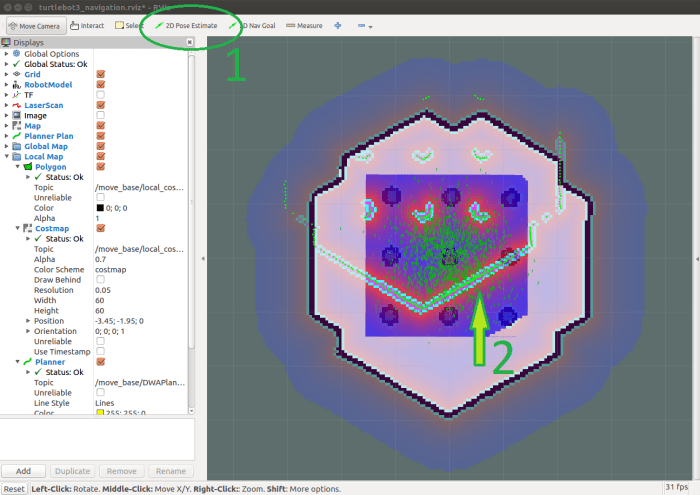
After realizing my beginner’s mistake of choosing the wrong ROS distribution to start my self-education, I set out to downgrade my ROS distribution from the newer but less supported “L” (Lunar) release to the previous “K” (Kinetic) release. Given the sheer number of different packages involved in a ROS installation, I had been worried this was going to be a tangled mess chasing down files all over the operating system. Fortunately, this was not the case, though there were a few hiccups that I’ll document today for other fellow beginners in the future.

The first step is to undo the package installation, which can be accomplished by asking the Ubuntu package manager to remove the desktop package I used to install.

sudo apt remove ros-lunar-desktop-full

Once the top-level package was removed, all of its related packages were marked as unnecessary and could be auto-removed.

sudo apt autoremove

At this point ROS Lunar is gone. If a new terminal is opened at this point, there will be an error because the Lunar setup script called by ~/.bashrc is gone.

bash: /opt/ros/lunar/setup.bash: No such file or directory

This is not an immediate problem. We can leave it for now and install Kinetic.

sudo apt install ros-kinetic-desktop-full

After this completes, we can edit ~/.bashrc and change the reference from /opt/ros/lunar/setup.bash to /opt/ros/kinetic/setup.bash. This will address the above “No such file or directory” error when opening up a new terminal.

Then we can fix up the build environment. If we now go into the catkin workspace and run source devel/setup.bash as usual, that command will succeed but trying to run catkin_make will result in an error:

The program 'catkin_make' is currently not installed. You can install it by typing:

sudo apt install catkin

This is a misleading error message because catkin_make was installed as part of ROS Kinetic. However, devel/setup.bash still pointed to ROS Lunar which is now gone and that’s why our system believes catkin_make is not installed.

How to fix this: open a new terminal window but do NOT run source devel/setup.bash. Go into the catkin workspace and run catkin_make there. This will update devel/setup.bash for ROS Kinetic. After this completes, it is safe to run source devel/setup.bash to set up ROS Kinetic. Now catkin_make will execute successfully using ROS Kinetic version of files, and we’re back in business!