Breadboard Prototype of VFD Driver Project

Once we had some idea of what we wanted to do, it’s time to start wiring things up on a breadboard to see if it actually does anything interesting. Dealing with actual chips meant reading their data sheets and figure out where the rubber meets the road and how well theory meets practice.

Not having a lot of first-hand experience with such modules, it was a great way to learn by doing. The first surprise was behavior of the 74HC138 decoder module: Conceptually it takes a three-bit input and decodes it to one of eight pins. Conceptually we thought that meant raising one of eight pins high, but it actually lowers one of eight pins low.

We thought this was going to be a problem and started looking into inverters… before we realized it is a perfect pairing with ULN2003 to do what we actually wanted: The ULN2003 line inverts its input in the sense that when an input pin is high it connects the output pin to ground. So the output of a 74HC138 decoder (seven pins high, one pin low) driving ULN2003 results in seven pins connected to ground and one floating. We can work with this.

A 4-digit, 7-segment LED module stood in for the vacuum fluorescent display while all the logic got worked out. This flexibility is exactly where a breadboard is strong, letting us experiment and verify pieces of our circuit piecemeal. But it is not great for looking respectable or for long-term reliability, so once it successfully ran the LED module, we start planning to commit the design to soldering parts on a prototype PCB.

PIC16F18345 VFD breadboard and PCB

Hardware Side of Keeping PIC Driver Simple

For the VFD driver project, there were software design motivations to keep things simple. But that’s not the whole picture, there were also motivation from hardware constraints too. My previous projects to make a PIC drive a multi-segmented LED display had fairly simple wiring that connected most output pins of my PIC to current-limiting resistors. A few of the lines could have seen current flow higher than what a PIC is capable of handling, and those were handled with simple transistors. I knew there existed chips designed specifically to drive LEDs, but I wanted to learn the principles of controlling one myself.

Building something to drive a VFD requires dealing with voltages different and sometimes far higher than what is required to drive LED display modules. During our probe of this specific VFD we saw 2.5V AC and 30V DC, atypical of logic circuits. And just as there existed dedicated LED driver chips, there exist chips specifically designed to drive VFD modules, but again the project goal was to learn by building one ourselves.

So we turn to our standard electronic hobbyist toolbox item for controlling power and voltage beyond what our standard parts can handle: the ULN2003A line of Darlington arrays. The go-to solution for controlling inductive loads like relays and small motors, it can handle voltages up to 50V which we need for a VFD.

And again, with multiple different display projects on the horizon, it didn’t make sense to create a controller with hardware pinout specifically tailored to a specific unit. To keep things simple and consistent across displays, all of our controller outputs will be either left floating or tied to ground. If a particular device desires a particular pin to be at a higher voltage, we’ll have to wire up a pull-up resistor on that device’s specific interface board. We will learn if this concession to consistency will cause problems down the line.

VFD driver schematic

Why And How Of Simpler PIC Display Driver

Earlier in my outline for starting a new PIC display driver project for a vacuum fluorescent display (VFD), I mentioned one objective was to “keep the PIC side very simple and move more display-specific logic into driving code“. Let’s go into more detail on that part of the plan.

In my previous PIC display projects, the code was written for a specific multi-segment display unit as part of the overall project. This meant the source code reflected whether the LED was a common-anode or common-cathode design, it also knew about which segment represented which parts of a particular digit. This knowledge was required because I put priority on making control communication interface easy. For the temperature demo, making my display unit show “72.3F” was a matter of sending the actual UTF-8 text string “72.3F” as bytes. The PIC then parsed that string and determined which segment to illuminate.

But there’s a good chance we have several other matrix display projects in the future, and I didn’t want to invest the time to hard code intricacies of each unit into the PIC. It would be much easier to adapt and experiment if such logic was moved to a more developer-friendly environment like Python on a Raspberry Pi. In the case of the current NEC VFD under consideration, there are segments corresponding to days of the week and other function specific segments like an “On and “Off” text, “OTR”, little clock icon, etc. Most of which won’t necessarily be present on another VFD unit, why spend the time to embed such knowledge in my PIC driver?

NEC VSL0010-A VFD Annotated

We also want the flexibility to explore using the display in ways that are far afield of its original intent. For starters, that seven-segment display in the center doesn’t have to be constrained to display numbers for a clock. All these desires meant moving away from performing data interpretation on the PIC.

Instead, the PIC will accept a raw data stream where each bit corresponds to whether a segment is on or off. Each byte will correspond to 8 segments in a grid, and so forth. This means the task of mapping a desired digit to a set of segments will be the responsibility of driver code on host device rather than PIC peripheral. PIC will only concern itself with rapidly cycling through the matrix of digits keeping them all illuminated.

Old Microchip MCC Boilerplate for MSSP Requires C90 Compatibility Mode

PIC16F18345 VFD driver PCB

I’ve figured out how to compile the new Microchip Foundation Services Library boilerplate code for implement I²C peripheral, only to learn it doesn’t do what I wanted it to do. Well darn, it’s time to go back to the tried-and-true I²C boilerplate code I’ve used in earlier projects. It’s still there, it compiles with only the “this is outdated” warning, and I knew it worked well enough to be a good starting point for my projects. It was the tried-and-true known quantity that shouldn’t give me any trouble at all.

Except it did.

The code compiled fine, but it didn’t actually work. It would give a response to the first I²C query but then it would stop responding. Here’s the default boilerplate code, which responds to address 0x08, as probed by a Raspberry Pi using i2cdetect tool.

pi@raspberry:~ $ i2cdetect -y 1
     0  1  2  3  4  5  6  7  8  9  a  b  c  d  e  f
00:          -- -- -- -- -- 08 -- -- -- -- -- -- --
10: -- -- -- -- -- -- -- -- -- -- -- -- -- -- -- --
20: -- -- -- -- -- -- -- -- -- -- -- -- -- -- -- --
30: -- -- -- -- -- -- -- -- -- -- -- -- -- -- -- --
40: -- -- -- -- -- -- -- -- -- -- -- -- -- -- -- --
50: -- -- -- -- -- -- -- -- -- -- -- -- -- -- -- --
60: -- -- -- -- -- -- -- -- -- -- -- -- -- -- -- --
70: -- -- -- -- -- -- -- --

That part looks good, the problem comes when we run the same tool again.

pi@raspberry:~ $ i2cdetect -y 1
     0  1  2  3  4  5  6  7  8  9  a  b  c  d  e  f
00:          -- -- -- -- -- -- -- -- -- -- -- -- --
10: -- -- -- -- -- -- -- -- -- -- -- -- -- -- -- --
20: -- -- -- -- -- -- -- -- -- -- -- -- -- -- -- --
30: -- -- -- -- -- -- -- -- -- -- -- -- -- -- -- --
40: -- -- -- -- -- -- -- -- -- -- -- -- -- -- -- --
50: -- -- -- -- -- -- -- -- -- -- -- -- -- -- -- --
60: -- -- -- -- -- -- -- -- -- -- -- -- -- -- -- --
70: -- -- -- -- -- -- -- --

It has disappeared from scan, as it no longer responds to I²C commands sent to its address.

Comparing the I²C boilerplate code with my old LED project, I saw no differences worth mentioning. It should be the exact same code but it no longer does the exact same thing. What has changed between my old LED project and now?

Eventually I found the answer: Microchip has updated the XC8 compiler to C99, and this compiler update causes problems with existing code. I previously saw this in the form of compiler errors on an empty MCC-generated project. I no longer see compiler errors on an empty project template but arguably this is worse: no compiler errors but silent changes in behavior.

The solution is the same as before: change project properties so XC8 compiler uses its old C90 compatible mode. Once I switched over, the I²C boilerplate code functioned as expected.

Project Properties

Since Microchip has marked this old I²C boilerplate code as deprecated, I don’t expect them to bring it up to date with the new compiler. And given its history of causing me headaches, I guess I’ll plan on using C90 mode for all my projects for the foreseeable future.

Getting Microchip Foundation Services Library I2C Boilerplate To Compile

PIC16F18345 VFD driver PCBMotivated by the desire to get an old VFD up and running for fun, I set up my PIC16F18345 to act as an I²C peripheral. I could write my own code from scratch, or I could build on top of boilerplate code published by Microchip for implementing an I²C slave device. My problem is that I had two choices – the new thing that doesn’t compile, or the old thing that is deprecated.

I’ve since figured out how to resolve the two error messages to compile the new thing, formally called Foundation Services Library.

The first compiler error message was this:

In file included from mcc_generated_files/USBI2C_app.c:25:
mcc_generated_files/drivers/i2c_slave.h:55:34: error: unknown type name 'interruptHandler'
void i2c_slave_setReadIntHandler(interruptHandler handler);
^

Searching elsewhere in the generated boilerplate, I found a declaration for interruptHandler in another different header file. Copying it into i2c_slave.h addressed the “unknown type name” error.

typedef void (*interruptHandler)(void);

However, that error was replaced by a warning that there are now duplicate declarations of interruptHandler. This seems silly – if there were a declaration to collide with, it should not have thrown an unknown type name error signifying the declaration’s absence.

MPLAB should either not throw the error, or not raise the warning, but it is doing both. I have yet to figure out if the toolchain is busted or if the boilerplate code is. For now, though, I could proceed to the next problem.

The second compiler error message was this:

mcc_generated_files/USBI2C_app.c:30:14: error: no member named 'SSP1IE' in 'PIE3bits_t'
PIE3bits.SSP1IE = 1;
~~~~~~~~ ^
1 error generated.

This one was easier to figure out – go into the header files for this chip and look for SSP1IE. I found it declared on PIE1bits instead of PIE3bits. So to get this code to compile, I changed the boilerplate code from this:

void USBI2C_Initialize(void){
PIE3bits.SSP1IE = 1;
i2c_slave_open();
}

To this:

void USBI2C_Initialize(void){
PIE1bits.SSP1IE = 1;
i2c_slave_open();
}

What does PIE1bits.SSP1IE actually do? I’m not sure so I’m not positive this is actually the correct fix. But at least all of the foundation boilerplate compiles, and I start browsing through sample code for MikroElektronika USB-I2C Click module to figure out what it does and what I can do with it. Reading through code and comments, I saw this comment block.

- This module only supports byte operations. Block read and write operations is
not yet supported by MCC Foundation I2C Slave Drivers.

This comment implies Microchip has decided to deprecate their previous I²C library even though the new library is unable to duplicate important functionality. If true, this is… unsatisfactory. I want block read and write operations for my project.

Now I’m even more motivated to stay with the old code, but unfortunately there were some complications with that, too…

Sawppy Field Repair Kit: Backup Electronics

About a month ago Mars rover Curiosity’s computer system had a hiccup and reset itself, causing its management team here on Earth to switch to its alternate computer. These two computers – referred to as Side-A and Side-B, allow Curiosity to run on one while mission team diagnoses the other. Initial reports indicate a problem with Curiosity computer’s on board data storage systems.

My rover Sawppy is modeled after Curiosity, and it’s only be a matter of time before Sawppy emulates its big brother with a data storage problem too – the microSD card on a Raspberry Pi 3 computer is a notorious point of failure. But Sawppy doesn’t have a redundant computer system on board that can be switched remotely. Since I’m typically not far away, I can walk up to my rover and perform replacement manually.

But I could only walk up and replace it if I had a replacement handy! This is growing in importance as Sawppy started getting booked for public appearances. When it’s just a hobbyist project it’s not a big deal if Sawppy encounters a problem, I just pack it up until I can get home to my workbench. But if we’re starting to get into situations where Sawppy is actually a featured item, we need to know how to make sure The Show Must Go On.

Thus the latest addition to Sawppy’s field repair (“first aid”) kit: Highest priority is a copy of Sawppy’s microSD card already configured with all necessary software. A microSD card is very small and light, so there’s no excuse not to have one always on hand.

Lower priority, for times when there’s space to spare, is a backup Raspberry Pi 3.

And lowest priority is a LewanSoul servo USB to half-duplex translation board required to operate LewanSoul servos. And while I’m at it, pack a replacement servo as well!

Sawppy backup electronics

Sawppy Flag Pole Now Mounted Magnetically

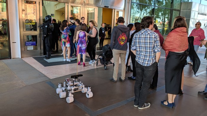
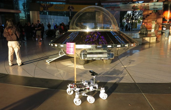
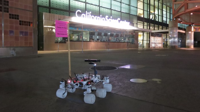
One of the problems I didn’t foresee in designing Sawppy was that some children might see a fun challenge in doing running jumps over my rover. I first saw this unwelcome behavior when I brought Sawppy to Long Beach, and I knew it’d only be a matter of time before a child would misjudge their jump and smash Sawppy into a pile of broken rover pieces.

Clearly I need to find some way to discourage this behavior, but I also can’t do anything that physically harms misbehaving children. This eliminates straightforward solutions such as a Samurai blade pointing straight up. I would also like this countermeasure to be stealthy and not call attention to its anti-jump purpose otherwise some would see it as a challenge.

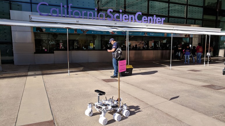
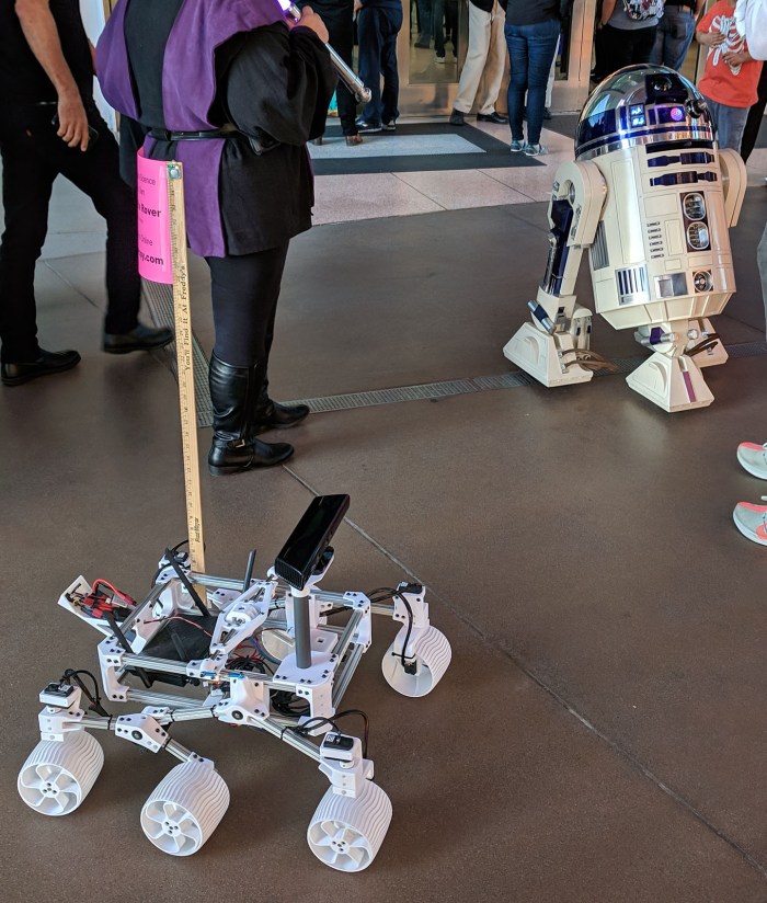
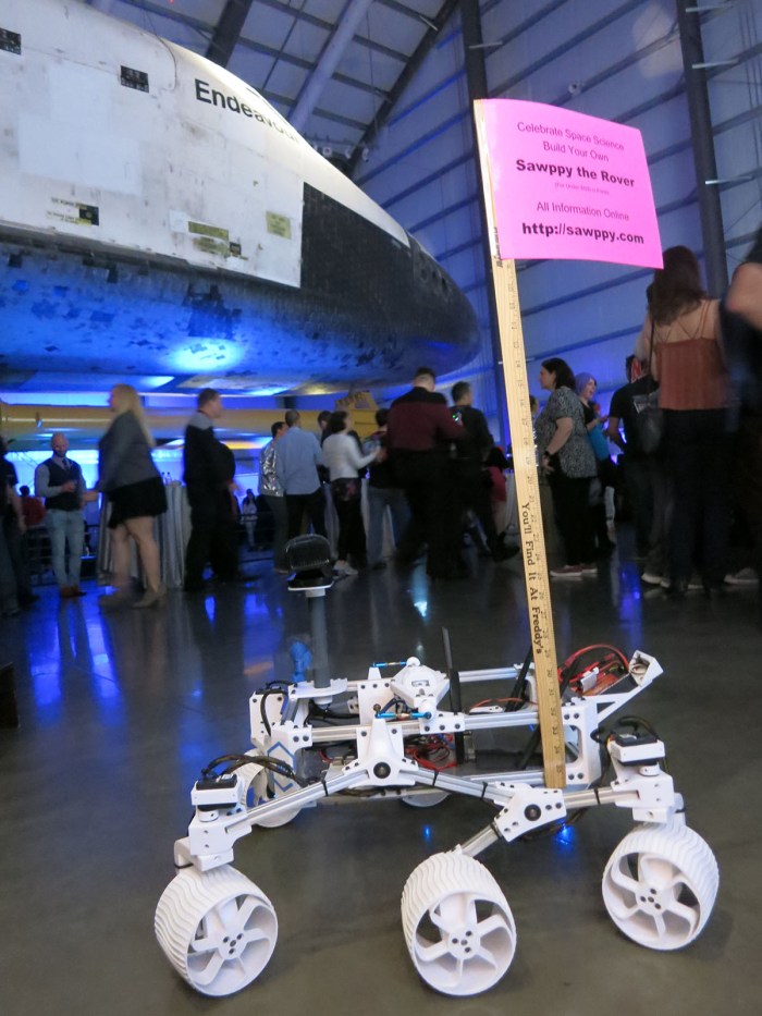
The answer came while preparing for this year’s Southern California Linux Expo (SCaLE 17x). I was scheduled to host the Hackaday x Tindie Birds of a Feather meetup, and I was also slated to co-present a talk with Lan Dang. For publicity purposes I decided Sawppy can be a rolling billboard, as SCaLE is exactly the right audience of people who would pay attention to a 3D-printed rover running about. I pulled out a yardstick I had on hand and started planning how to use it as a flag pole, and I immediately knew I had my anti-jumpover countermeasure as well. Two birds, one stone.

Sawppy Scale 17x Sat 1 - Roving billboard

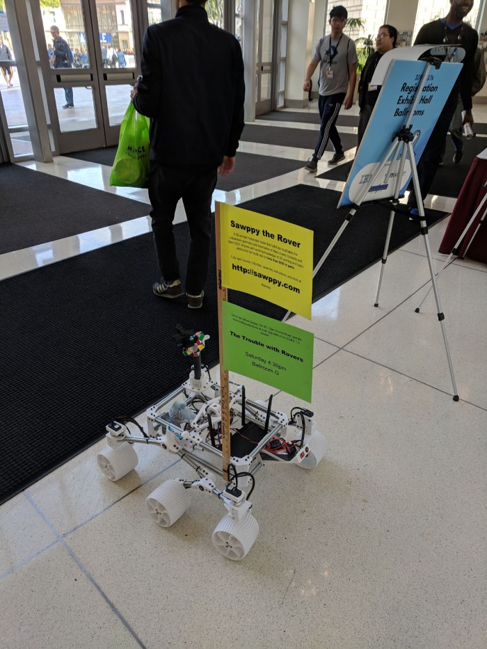
As previously mentioned, I didn’t want this flag pole to be too rigidly attached. If someone bumps my sign, or if someone decides to try jumping over my rover anyway, the flag pole must break away cleanly without damaging the person or the rover. For SCaLE I used a zip tie that was arranged so there is tension holding the yardstick flag pole in place, but pops free when stressed.

This mostly worked, but as it was built on a balance of opposing forces, it was finicky to reinstall. At Caltech Science for March, a curious toddler yanked off the flag pole and the toddler’s supervising elderly adult tried to reinstall the pole. But grandpa had no idea what he was doing, blindly stabbing inside Sawppy’s equipment bay with the yardstick applying more force as he grew more agitated. After two attempts at saying “Don’t worry, I’ll put it back myself” while I watched in horror at Sawppy electronics getting pummeled, I forcibly grabbed the yardstick from his hands in order to save Sawppy from being stabbed to death.

A better solution must be found.

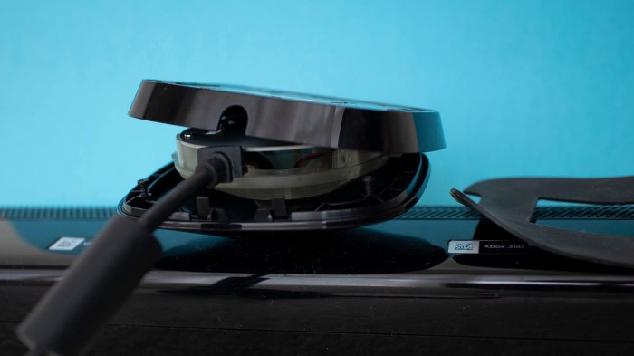
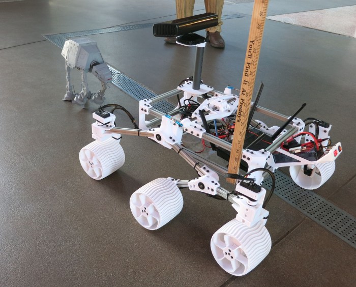
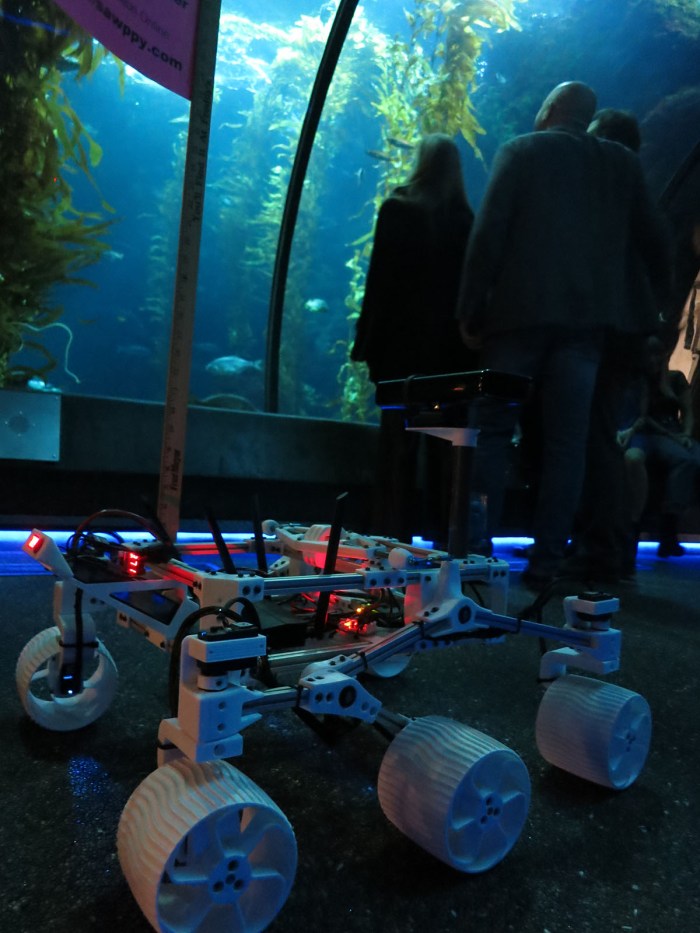
In preparation for Sawppy’s appearance at Yuri’s Night, I decided to try a magnetic mounting system. Originally rejected because I thought it wouldn’t be strong enough, I thought it was worth a second look. I had a stack of these powerful little magnets and a single pair wasn’t able to hold the pole. But four pairs of them might be strong enough for the task.

For this test, four magnets were held on to chassis beam via packing tape. Two on upper beam, two lower.

Sawppy magnetic flag mount

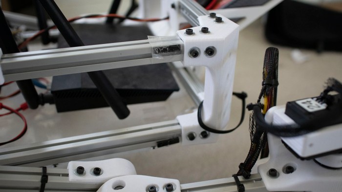
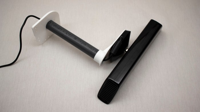
Matching sets were held to yard stick flag pole with more tape.

Sawppy magnetic flag mount with pole

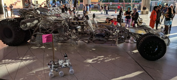
With updated camera mast and flag pole mount, Sawppy was ready for its next public appearance at Yuri’s Night Los Angeles! That event got crowded at times and there were a few accidental bumps that triggered a clean separation followed by quick re-installation. And while this adult-focused event had few children about, there were plenty of drunken misbehaving adults. The flagpole did not discourage all misguided behavior, but it has worked well enough to become a permanent fixture of my future Sawppy public appearances.

Sawppy with new camera and flag pole

(Cross-posted to Hackaday.io)

Sawppy Mount For Kinect V1

When Sawppy first started running around, I wanted something to sit atop a camera mast where the real rover has a camera and sensor array. It is the anthropomorphic head of the rover and it looks slightly wrong without one. (Like a chicken running around without its head.) The first iteration of camera mast sensor array enlisted a standard USB webcam sitting alongside a Google AIY Vision kit. It was mostly for appearance because there wasn’t much software behind it.

The webcam was fun for entertaining children and occasional longer distance driving, but not immediately useful for autonomy. The AIY Vision box is optimized for classification tasks. I thought there might exist code useful for robotic visual localization but if it’s out there I have yet to find it.

The most promising tool at hand for rover localization is my Kinect sensor bar running RTAB-Map or some similar software. So Sawppy will inch towards autonomy by getting a camera mast upgrade to my Kinect V1 sensor bar and see if we can integrate that into rover systems in a useful way.

I went looking for a good way to mount a Kinect bar to Sawppy. I disassembled its base looking for a good mounting mechanism, but there weren’t convenient existing fasteners for me to use and there weren’t good places for me to drill and tap new ones. It was surprisingly crowded in there! I knew there was a motor for up/down tilt but I underestimated size of the motor gearbox inside.

Kinect v1 base disassembled

I then reassembled the base and went with plan B: a simple flat platform for attaching my Kinect sensor bar with double-sided foam tape.

Printing Sawppy Kinect v1 platform

Kinect sits slightly offset camera mast center for two reasons.

  1. The Kinect sensor bar is very wide and if mounted centrally it overhangs to the right. I worry about it hitting obstacles so I wanted to bring it closer to the middle.
  2. By offsetting sideways, I could expose the top of the pipe used as camera mast and run Kinect’s wire down the middle for cleaner wire management.

Sawppy Kinect v1 installed on platform

At the moment this Kinect is no more functional for autonomy than the previous configuration… in fact, for its first public appearance at Yuri’s Night 2019 it is not even electrically connected to anything. It’s just a matter of taking one step at a time.

(Cross-posted to Hackaday.io)

Sawppy at Yuri’s Night LA 2019

Yesterday Sawppy attended Yuri’s Night Los Angeles 2019 as a roaming exhibit to help entertain the audience who all have an enthusiasm for space and science. As part of the volunteer event staff, we had to arrive at event venue California Science Center an hour ahead to get checked in. I noticed the signs and logos actually combined the second and third words into “California ScienCenter” but it’s not clear if this is just a bit of artistic license in graphic design or if they’re actually working to rename themselves. Once checked-in, Sawppy’s assignment was to roam and entertain guests waiting in line to enter.

Yuris Night 2019 02 - Sawppy mingles with entrance line

Sawppy was not the only robotic entertainment present.

Yuris Night 2019 03 - Sawppy and R2-D2

Sawppy was occasionally stopped in its tracks when challenged by an Imperial AT-AT.

Yuris Night 2019 04 - Sawppy and AT-AT

I was surprised to learn this was sold as a popcorn bucket sold at Disneyland. The owner gave it additional surface treatment and added LEDs, but he said almost all of the physical detail (including legs that could be posed) were part of the original bucket. Sadly, it was not motorized and did not walk.

Once people in line got in and the front entrance crowd thinned out, Sawppy went visiting other front entrance displays. Largest by far was Mister Fusion, which I first saw on TV in the first episode opening of Amazon’s The Grand Tour(*). There, and also on its web page, it was advertising for iHeartRadio. It is now advertisement for a mixed-use development project in Las Vegas called Area 15. The sales pitch for this “experiential retail and entertainment complex” sounded interesting, once it opens it might be worth a stop on my next Vegas visit.

Yuris Night 2019 05 - Sawppy and Mister Fusion

Model of real Earth probe sent to space meets model of fictional Martian probe sent to Earth: Sawppy and a very shiny UFO.

Yuris Night 2019 06 - Sawppy and UFO

At one point there was discussion of a display of Star Wars cars, which was the context of how I originally got involved with my RXBB8. That was removed from the plan at some point, but Sci-Fi cars still had representation with one of the Back to the Future DeLorean replicas.

Yuris Night 2019 07 - Sawppy and DeLorean

Main space for this event was in the Space Shuttle Endeavour room, where photography was difficult but I wanted a picture of Sawppy with a real spacecraft.

Yuris Night 2019 08 - Sawppy and Endeavour

Lots of people loved Sawppy and asked many interesting questions about Mars rovers. The event had everyone from “I don’t know much about the Mars rovers but I want to hear about them” to JPL engineers who are actively working on building the Mars 2020 rover. My discussion topics with people fluctuated wildly to suit.

At the end of the night, guests for the event were directed through the kelp forest tunnel to exit.

Yuris Night 2019 09 - Sawppy in Kelp Forest

After a full night hanging out with other space fans, Sawppy headed home.

Yuris Night 2019 10 - Sawppy Heads Home


(*) Disclosure: As an Amazon Associate I earn from qualifying purchases.

I2C on PIC: Microchip Foundation Services Library Is Less Beginner-Friendly

About a year and a half ago I poked my head into the world of I²C programming with my PIC16F18345 chip. I was pleasantly surprised the MCC boilerplate code actually included an example implementation emulating an I²C EEPROM. That turned out to be a great way for me to get started.

Now that I have another PIC project in mind, I retraced my steps and saw this:

I2C driver will be removed soon

In file included from mcc_generated_files/mcc.h:55:
mcc_generated_files/i2c1.h:55:2: warning: "This version of the I2C driver will be removed soon and the correct driver to use is the Foundation Services driver" [-W#warnings]
#warning "This version of the I2C driver will be removed soon and the correct driver to use is the Foundation Services driver"

Looks like what I had used before is on its way out.

Since this is a new project, I thought I might as well check out what the new shiny object has to offer. Reading around the web, I found complaints that the previous MCC I²C code would work when conditions are ideal, but it was not very good at letting developers write code to handle error conditions. This might not be important in hobbyist projects like mine, but it was of great importance to people trying to engineer real products.

I added the Foundation Services Library module for my PIC’s MSSP. After code generation was complete, I went into the generated header files and saw a lot more functions declared than previous boilerplate code. There were a few related to overflow and bus collision errors, which I assume were there to address complaints about error handling capability.

Unfortunately, there is no longer a friendly example implementation to reference. There are a lot of declarations but no information on how to use those functions. Microchip’s claim that the Foundation Services Library code is self-documenting has been wholeheartedly laughed at by other forum users. But the forums did point me to Microchip’s  MikroElektronika Click Library which interfaces between those nifty little Click modules to a PIC using Foundation Services Library. The trick is finding one that most closely matches what I’m trying to do. Many Click modules are I²C slaves controlled by a PIC acting as master, I wanted my PIC to act as I²C slave accepting commands. A first pass through the Click library found only the USB-I2C Click module, so I installed sample code corresponding to that module and tried to build it.

unknown type name interruptHandler

In file included from mcc_generated_files/USBI2C_example.c:36:
mcc_generated_files/drivers/i2c_slave.h:54:34: error: unknown type name 'interruptHandler'
void i2c_slave_setReadIntHandler(interruptHandler handler);

Sample code that fails to compile is… not the height of beginner friendliness.

After 30 minutes of hunting around, I failed to find a solution to this problem and decided to return to the old deprecated I²C driver. It may not be the newest and shiniest thing, but it does compile and run.

Dusting off Past PIC LED Driver Projects For Potential VFD Driver

While the VFD salvaged from a VHS timer/tuner unit was designed to run on voltages unfamiliar to me, once we probed the control pinout I found it much less intimidating. The entire array can be treated as a matrix with its eight grids along one axis and ten elements along another axis. The array is only partially filled: there aren’t actually 80 elements on the VFD. A driver chip will energize one grid at a time, and energize the desired elements within that grid. After some time, the driver will move on to the next grid and its corresponding elements. When the switching happens quickly enough, our human eye sees only a completely illuminated display and would not notice that grid-to-grid cycling.

NEC VSL0010-A VFD Annotated

This general principle is identical to how I drove a LTC-4627JR 7-segment LED array in an earlier PIC project. The only real difference is that the transistors I had used earlier is only good for the +5V used by that LED array and not suitable for +30V for this VFD, but that can be addressed by substituting some switching components.

IMG_5272

In the previous project, I was interested in learning KiCAD and the process of ordering custom PCBs for a device for potential low-volume production. Many lessons were learned, most of which discouraged me from pursuing the thought further. This time around there is no fantasy of volume production, this will be an one-off project for a single salvaged VFD.

But now that I know the concept of a display matrix is generically applicable across multiple units, this time around I’m more inclined to keep the PIC side very simple and move more display-specific logic into driving logic which usually runs on a more programmer-friendly device like an Arduino or Raspberry Pi. (Or maybe even a ESP32!) So this time around I’m not going to decode ASCII characters or anything along those lines: I’m going to create a PIC driver that listens for commands over I2C specifically about cycling through and toggling pins. The idea is to avoid unnecessary PIC code churn that uselessly reinvent the wheel from one LED display to another, instead moving that to the Arduino/Pi/ESP32/etc side.

IMG_5238

Original NEC VSL0010-A VFD Power Source

Now that we have a better understanding of how a NEC VSL0010-A vacuum fluorescent display (VFD) works, figuring out its control pinout with the help of an inkjet power supply, we returned to the carcass we salvaged that VFD out of. Now that we knew each pins’ function, we picked those that supplied 2.5V AC for filament power to track. We expect they are least likely to pass through or be shared by other devices. We traced through multiple circuit boards back to the main power transformer output plug. We think it’s the two gray wires on the left side of this picture, but our volt meter probes are too big to reach these visible contact points. And the potential risk of high voltage made us wary of poking bare wires into that connector as we did for the inkjet power supply.

NEC VSL0010-A VFD Power Supply - Probes Too Fat

Our solution came as a side benefit of decision made earlier for other reasons. Since we were new to VFD technology, our curiosity-fueled exploratory session was undertaken with an inexpensive Harbor Freight meter instead of the nice Fluke in the shop. Originally the motivation was to reduce risk: we won’t cry if we fry the Harbor Freight meter, but now we see a secondary benefit: With such an expensive device, we also feel free to modify these probes to our project at hand. Off we go to the bench grinder!

NEC VSL0010-A VFD Power Supply - Probes Meet Grinder

A few taps on the grinding wheel, and we have much slimmer probes that could reach in towards those contacts.

NEC VSL0010-A VFD Power Supply - Probes Now Thin

Suitably modified, we could get to work.

NEC VSL0010-A VFD Power Supply - Probes At Work

We were able to confirm the leftmost pair of wires, with gray insulation, is our 2.5VAC for VFD filament. The full set of output wires from this transformer, listed by color of their insulation, are:

  • Gray pair (leftmost in picture): 2.6V AC
  • Brown pair (spanning left and right sides): 41V AC
  • Dark blue pair: (center in picture) 17.2V AC
  • Black pair (rightmost in picture): 26.6V AC

There was also a single light-blue wire adjacent to the pair of dark blue wires. Probing with volt meter indicated it was a center tap between the dark blue pair.

NEC VSL0010-A VFD Power Supply Transformer

Once determined, we extracted the transformer as a single usable unit: there was a fuse holder and an extra power plug between it and the device’s AC power cord. We’re optimistic this assembly will find a role in whatever project that VFD will eventually end up in. 2.6V AC can warm filament, rectified 26.6V AC should work well for VFD grid and segments. And with proper rectification and filtering, a microcontroller can run off one of these rails. It’ll be more complex than driving a LED display unit, but it’ll be worth it for that distinctive VFD glow.

HP Inkjet Printer Power Supply For NEC VSL0010-A VFD

One of the reasons LED has overtaken VFD in electronics is reduced power requirements. Not just in raw wattage of power consumed, but also the varying voltage levels required to drive a VFD. The NEC VSL0010-A VFD whose pinout we just probed ran on 2.5V AC and ~30V DC. In contrast, most LED can run at the same 5V or 3.3V DC power plane as their digital drive logic, vastly simplifying design.

We didn’t have a low voltage AC source handy for probing, so we used 2.5V DC. We expected this to have only cosmetic effects. One side of our VFD will be brighter than the other, since one side will have a filament-to-grid/element voltage difference of 30V but the other will only have 27.5V.

But putting 2.5V DC on the filament occupied our only bench power supply available at the time. What will we use for our 30V DC power source? The answer came from our parts pile of previously disassembled electronics, in this case a retired HP inkjet printer’s power supply module labeled with the number CM751-60190.

HP CM751-60190 AC Power Adapter

According to the label, this module could deliver DC at 32V and 12V. Looking at its three-conductor output plug, it was easy to come to the conclusion we have one wire for ground, one wire for 32V, and one wire for 12V. But that easy conclusion would be wrong. Look closer at the label…

HP CM751-60190 AC Power Adapter pinout

We do indeed have a ground wire in the center, but there is only one power supply wire labelled +32V/+12V. It actually delivers “32 or 12” volts, not “32 and 12” volts. That last pin on the left has an icon. What did that mean? Our hint comes from power output specifications: +32V 1095mA or +12V 170mA. We deduced this meant the icon is a moon, indicating a way to toggle low-power sleep mode where the power supply only delivers 12V * 170mA = 2 watts vs. full 32V * 1095mA = 35 W.

With that hypothesis in hand, it’s time to hook up some wires and test its behavior.

HP CM751-60190 AC Power Adapter test

When “sleep mode” pin is left floating, voltage output is 32VDC. When that pin is grounded, voltage output drops to 12VDC. Since we’re looking for 32VDC to drive our VFD grid and elements, it’s easy enough to leave sleep wire unconnected and solder wires to the remaining two wires to obtain 32V DC for our VFD adventures.

HP CM751-60190 AC Power Adapter new wires

Sleuthing NEC VSL0010-A VFD Control Pinout

Vacuum Fluorescent Display (VFD) technology used to be the dominant form of electronics display. But once LEDs became cheap and bright enough, they’ve displaced VFDs across much of the electronics industry. Now a VFD is associated with vintage technology, and its distinctive glow has become a novelty in and of itself. Our star attraction today served as display for a timer and tuner unit that plugs into the tape handling unit of a Canon VC-10 camera to turn it into a VCR. A VFD is very age-appropriate for a device that tunes into now-obsolete NTSC video broadcast for recording to now-obsolete VHS magnetic tape.

Obviously, in this age of on-demand internet streaming video, there’s little point in bringing the whole system back to life. But the VFD appears to be in good shape, so in pursuit of that VFD glow, salvage operation began at a SGVHAK meetup.

NEC VSL0010-A VFD Before

We have the luxury of probing it while running, aided by the fact we can see much of its implementation inside the vacuum chamber through clear glass. The far right and left pins are visibly connected to filament wires, probing those pins saw approximately 2.5V AC. We can also see eight grids, each with a visible connection to its corresponding pin. That leaves ten pins to control elements within a grid. Probing the grid and element pins indicate they are being driven by roughly 30V DC. (It was hard to be sure because we didn’t have a constant-on element to probe…. like all VCRs, it was blinking 12:00)

This was enough of a preliminary scouting report for us to proceed with desoldering.

NEC VSL0010-A VFD Unsoldering

Predating RoHS solder that can be finicky, it was quickly freed.

NEC VSL0010-A VFD Freed

Now we can see its back side and, more importantly, its part number which immediately went into a web search on how to control it.

NEC VSL0010-A VFD Rear

The top hit on this query is this StackExchange thread, started by someone who has also salvaged one of these displays and wanted to get it up and running with an Arduino. Sadly the answers were unhelpful and not at all supportive, discouraging the effort with “don’t bother with it”.

We shrugged, undeterred, and continued working to figure it out by ourselves.

NEC VSL0010-A VFD Front

If presented with an unknown VFD in isolation, the biggest unknown would have been what voltage levels to use. But since we have that information from probing earlier, we could proceed with confidence we won’t burn up our VFD. We powered up the filament, then powered up one of the pins visibly connected to a grid and touched each of the remaining ten non-grid pins to see what lights up. For this part of the experiment, we got our 32V DC from the power supply unit of a HP inkjet printer.

We then repeated the ten element probe for each grid, writing down what we’ve found along the way.

NEC VSL0010-A VFD Annotated

We hope to make use of this newfound knowledge in a future project, and we hope this blog post will be found by someone in the future and help them return a VFD to its former glowing glory.

Making Neato Robot ROS Package More Generally Usable

Neato mini USB cable connection to laptopNow that I have some idea of what happens inside ROS package neato_robot, and modified it to (mostly) run on my Neato vacuum, I thought I’d look in its Github repository’s list of issues to see if I understand what people have said about it. I didn’t have to look very far: top of its open issues list is “Robot compatibility.”

The author agrees this is a good idea but it has to be done by someone with access to other Neato units, pull requests are welcome. This comment was dated four years ago but my experience indicates no pull requests to improve compatibility were ever merged into this code.

But even though modifications were never merged back into this branch, they are still available. I just had to be pointed to know where to look. That comment thread referenced this particular commit which eliminates those problematic fixed arrays of expected response strings. Now it will read a Neato’s responses without trying to match it up against a preset list. Of course, if a specific response is still required (like LeftWheel_PositionInMM and RightWheel_PositionInMM) all it could do is ensure code will not hang, it is not capable of inferring requested data from other robot responses.

But possibly more interesting than code changes is this comment block:

This driver reads responses until it receives a control-z. Neato Robotics has
documented that all responses have a control-Z (^Z) at the end of the
response string: http://www.neatorobotics.com.au/programmer-s-manual
CTRL_Z = chr(26)

That URL implies it was a link to some type of a programmer’s reference manual, but unfortunately that link is now dead. Still, this claim of control-Z termination (if true) gives me ideas on how I would approach talking to a Neato with my own code.

Instructions Posted For Running SGVHAK Rover Software on Sawppy Rover

I had always intended for Sawppy to be an adventure in building autonomous robots, but the Sawppy hardware I built and declared version 1.0 needed software of some sort in order to get up and running. Since I had code for SGVHAK Rover handy, I adapted it to control Sawppy as well. Both rover models had six wheel drive and four wheel steering resulting in large overlaps of functionality. I only had to write adapter code for it to communicate with Sawppy’s LewanSoul serial bus servos instead of SGVHAK Rover’s RoboClaw motor controllers.

At the time I was overly optimistic about how quickly I could get new software up and running on Sawppy. I didn’t climb the learning curve for ROS nearly as fast as I had hoped, requiring detours along the way to build learning robots like Phoebe. In the meantime Sawppy continued running on this “interim” software that threatens to become the permanent software with each passing day.

A symptom of optimism was my decision to not write very much documentation helping other Sawppy builders adapt SGVHAK rover software to run on their own rover. I thought I would have new software soon so why bother? At first this was not a problem – first three Sawppy builds I’m aware of were built by people who made modifications and used their own methods of rover control. (Two are writing their own software, the third was modified for standard remote control.)

But now I’m starting to receive queries from people who want to run SGVHAK rover code on their Sawppy rovers as well. While a talented few have been able to find their own way just by examining my Github repositories, it’s not very friendly to tell people “Go look at the code and figure it out.” I need to put in the time to write instructions for putting SGVHAK Rover software on Sawppy.

I’m happy to announce that this work is now complete and posted up on Sawppy’s build documentation repository. It walks through assigning unique IDs to LewanSoul serial bus servos, to which configuration files to edit, and which configuration files to just completely overwrite. I hope this will help more Sawppy builders get their rover up and running!

Serial-Servo-Rename

(Cross-posted to Hackaday.io)

Neato Robot ROS Package Splits Laser Scan Read Operations

Neato mini USB cable connection to laptopI want to understand how the neato_robot ROS package works, and debugging its hang inside getMotors() was a great first step. Now that I’m past the problem of mismatching responses between author’s Neato robot vacuum and mine, I started looking at other parts of neato_driver.py for potential explanations to its new (possibly timing-related) hang.

Since I had just examined getMotors(), I looked at its counterpart setMotors() and found nothing remarkable. getAnalogSensors(), getDigitalSensors(), and getCharger() used the exact pattern as getMotors() which meant they share the same fragility against different Neato responses but they’ll work for now. setBacklight() is nearly trivial.

That leaves the two methods for reading Neato’s laser distance scanner. Wait, two? Yes, and that’s where my concern lies. Other data retrieval methods like getMotors() would issue a command and then parse its response before returning to caller. For the laser distance scanner, this is split into a requestScan() which issues a getldsscan command and immediately returns. Reading and parsing laser distance data is done in a separate method getScanRanges() which the caller is expected to call later.

Why was this code structured in such a manner? My hypothesis is this was motivated by performance. When a getldsscan command is issued over serial, a lot of data is returned. There are 360 lines of data, one for each degree of laser scanning with distance and intensity information, plus a few more lines of overhead. This is far more than any of the other data retrieval methods. So rather than wait for all that data to transmitted before it could be processed, this two-call pattern allows the caller to go off and do something else. The transmitted data is trusted to be buffered and waiting in serial communication module.

But this only works when the caller is diligent about making sure these two calls always follow each other, with no chance for some other command to accidentally get in between. If they fail to do so, everything will fall out of whack. Would that cause the hang I’ve observed? I’m not sure yet, but it would be better if we didn’t even have to worry about such things.

Neato Robot ROS Package Expects Specific Response But Responses Actually Differ Between Neato Units

Neato mini USB cable connection to laptop

I got the outdated neato_robot ROS package mostly working just by adding a timeout to its serial communications. But this only masked the symptom of an unknown problem with no understanding of why it failed. To understand what happened, I removed the timeout and add the standard Python debugging library to see where it had hung.

import pdb; pdb.set_trace()

I found the hang was getMotors() in neato_driver.py. It is waiting for my Neato to return all the motor parameters specified in the list xv11_motor_info. This list appears to reflect data returned by author’s Neato robot vacuum, but my Neato returns a much shorter list with only a partial overlap. Hence getMotors() waits forever for data that will never come. This is a downside of writing ROS code without full information from hardware maker: We could write code that works on our own Neato, but we would have no idea how responses differ across different robot vacuums, or how to write code to accommodate those variations.

Turning attention back to this code,  self.state[] is supposed to be filled with responses to the kind of data listed in xv11_motor_info.  Once I added a timeout, though, getMotors() breaks out of its for loop with incomplete data in self.state[].  How would this missing information manifest? What behavior does it change for the robot?

Answer: it doesn’t affect behavior at all. At the end of getMotors()we see that it only really cared about two parameters: LeftWheel_PositionInMM and RightWheel_PositionInMM. Remainder parameters are actually ignored. Happily, the partial overlap between author’s Neato and my Neato does include these two critical parameters, and that’s why I was able to obtain /odom data running on my Neato after adding a timeout. (Side note: I have only looked to see there is data – I have not yet checked to see if /odom data reflects actual robot odometry.)

Next I need to see if there are other similar problems in this code. I changed xv11_motor_info list of parameters to match those returned by my Neato. Now getMotors() will work as originally intended and cycle through all the parameters returned by my Neato (even though it only needs two of them.) If this change to neato_robot package still hangs without a timeout, I know there are similar problems hiding elsewhere in this package. If my modification allow it to run without a timeout, I’ll know there aren’t any others I need to go hunt for.

Experiment result: success! There are no other hangs requiring a timeout to break out of their loop. This was encouraging, so I removed import pdb.

Unfortunately, that removal caused the code to hang again. Unlike the now-understood problem, adding a timeout does not restore functionality. Removal of debugger package isn’t supposed to affect behavior, but when it does, it usually implies a threading or related timing issue in the code. This one will be annoying as the hang only manifests without Python’s debugging library, which meant I’d have to track it down without debugger support.

Rover Mr. Blue Now Up And Running On SGVHAK Rover Code

Mr. Blue is alive

While I’m making my way learning how to write proper modules for Robot Operating System, the rest of my SGVHAK compatriots have not been twiddling their thumbs waiting. Just like I went and built Sawppy as my idea of a cool rover project, Dave designed and built Mr. Blue as his idea of a cool rover.

All the blue printed plastic parts (which gave this rover its name) was designed in Dave’s preferred CAD software OpenSCAD. These pieces connect thin wall aluminum tubing that is very strong yet quite affordable. Making this rover a great exploration into a construction method quite different from Sawppy, where I designed 3D-printed plastic components in Onshape CAD and they connected Misumi aluminum extrusion beams.

Mr. Blue also expresses Dave’s ability to design and build electronics circuits. Where my Sawppy used serial bus servos, Dave has custom controller boards driving all the motors. There are two types on board: one drives a DC motor with feedback provided by optical quadrature encoders, the other drives a commodity servo motor but with precise position feedback via high-resolution magnetic encoders. In both cases, they feed into a 3D-printed gearbox for additional mechanical reduction.

Originally, the plan was to get Mr. Blue up and running on ROS, but Dave’s progress at construction was faster than my progress at learning ROS. As an interim solution, I added support for Dave’s motor control boards to my SGVHAK Rover software project. Now we have the same basic software running three rovers built with three different motor systems:

We have quite a rover family going!

Neato Robot ROS Package Runs After Adding Serial Communication Timeout

Neato mini USB cable connection to laptop

The great thing about ROS is that it is a popular and open platform for everyone to work with, resulting in a large ecosystem of modules that cover a majority of robot hardware. But being so open to everyone does have a few downsides, because not everyone has the same resources to develop and maintain their ROS modules. This means some modules fall out of date faster than others, or works with its author’s version of hardware but not another version.

Such turned out to be the case for the existing neato_robot ROS package, which was created years ago and while the author kept updated it through four ROS releases, that maintenance effort stopped and so this code is now five releases behind latest ROS. That in itself is not necessarily a problem – Open Source Robotics Foundation tries to keep ROS backwards compatible as much as they can – but it does mean potential for hidden gotchas.

When I followed instructions for installation and running, the first error message was about configuring the serial port which was fine. But after that… nothing. No information published to /odom or /base_scan, and no response to command sent to /cmd_vel.

Digging into the source code, the first thing to catch my attention was that the code opened a serial port for communication but did not set provision for timeout. Any problem in serial communication will cause it to hang, which is exactly what it is doing now. Adding a timeout is a quick and easy way to test if this is actually related.

Existing:

self.port = serial.Serial(port,115200)

Modified:

self.port = serial.Serial(port,115200,timeout=0.01)

And that was indeed helpful, restoring nominal functionality to the ROS node. I could now drive the robot vacuum by sending commands to /cmd_vel and I can see a stream of data published to /odom and /base_scan.

I briefly contemplated being lazy and stopping there, but I thought I should try to better understand the failure. Onward to debugging!