Death Clock User Input Integration

After our brief orientation on a capacitive touch input sensor, Emily and I started looking into how we would integrate it into our Death Clock project. During the course of this research we also learned that according to Microchip our PIC microcontroller is supposedly capable of touch input as well, without needing a separate sensor peripheral. We’re going to file that information away for another day since already got this touch board in hand and we’ve learned enough to try using it.

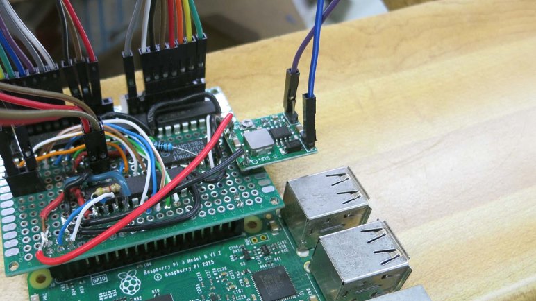
Since our Death Clock state machine will be running on our Raspberry Pi, it made the most sense to interface this touch board to our Pi via one of its available GPIO pins. I had previously soldered an extra pair of pins and at the time it was merely for the purpose of mechanical support. Looking on a Raspberry Pi GPIO reference chart, though, we see these two pins (#39 and 40 on the pinout chart) are GPIO21 and GND and coincidentally perfect for our use. Our touch sensor board signals detection by pulling its output signal line to ground, so once we’ve configured GPIO21 for digital input with internal pull-up, we can easily test (without sensor board) by grounding GPIO21 to its adjacent GND pin with a piece of conductive metal like a paperclip or a coin.

Raspberry Pi GPIO pins can tolerate a maximum of 3.3 volts, so for the actual sensor board we’ll have to tap power from 3.3V pin on Pi header instead of the 5V we’re using for our PIC. Ground and GPIO21 already have headers, and those three points are all we need to wire up our touch sensor to our Pi. After that the sensor board requires just one more wire – the touch sense input wire – but that will lead elsewhere in the Death Clock enclosure and not to the Raspberry Pi.

Death Clock Code Organization

When we established our set of display states for the Death Clock project, we knew there would need to be a state machine somewhere in its logic to manage those display states. And when we designated different zones that can be composited together for a single frame in our display animation, we knew there would need to be some kind of animation engine in charge of corresponding work. These requirements formed our starting point for designing and organizing code for Death Clock.

The state machine was implemented as an infinite loop running an if/elif/else loop checking for our state value. Each clause corresponds to a display state and has (1) calls to code handling that display and (2) conditions to transition to another state. The state machine resides in a single class deathclock which also owns the reference to Pi GPIO library for display. It may make sense to split the I2C communication to another class but there’s no need to do so just yet.

Different display states require different operations to assemble their animation frame. An attempt to create a master animation engine capable of all operations became unnecessarily complex and was eventually abandoned. Instead, we’ll have multiple classes (nyancat, thinkingface, and deathtime) each of which will stay focused on the type of operations required for a single display state. This keeps the simple animations simple, and allows us to experiment with more complex animations without fear of damaging unrelated display states. This will result in some code duplication that we can come back to refactor later, but keeping each display state animation code separate lets us iterate ideas faster.

Code discussed in this blog post is available on Github.

Raspberry Pi GPIO Library Gracefully Degrades When Not On Pi

Our custom drive board for our vacuum fluorescent display (VFD) is built around a PIC which accepts commands via I2C. We tested this setup using a Raspberry Pi and we plan to continue doing so in the Death Clock project. An easy way to perform I2C communication on Raspberry Pi is the pigpio library which was what our test programs have used so far.

While Emily continues working on hardware work items, I wanted to get started on Death Clock software. But it does mean I’d have to work on software in absence of the actual hardware. This isn’t a big problem, because the pigpio library degrades gracefully when not running on a Pi. So it’ll be easy for my program to switch between two modes: one when running on the Pi with the driver board, and one without.

The key is the pigpio library’s feature to remotely communicate with a Pi. The module that actually interfaces with Pi hardware is called the pigpio daemon, and it can be configured to accept commands from the local network, which may or may not be generated by another Pi. Which is why the pigpio library could be installed and imported on a non-Pi like my desktop.

pigpiod fallback

For development purposes, then, I could act as if my desktop wants to communicate with a pigpio daemon over the network and, when it fails to connect, fall back to the mode without a Pi. In practice this means trying to open a Pi’s GPIO pins by calling pigpio.pi() and then checking its connected property. If true, we are running on a Pi. And if not, we go with the fallback path.

This is a very straightforward and graceful fallback to make it simple for me to develop Death Clock code on my desktop machine without our actual VFD hardware. I can get the basic logic up and running, though I won’t know how it will actually look. I might be able to rig up something to visualize my results, but basic logic comes first.

Code discussed in this blog post are visible on Github.

Display Zones of Vacuum Fluorescent Display

Now that we have a set of states for what to display on our vacuum fluorescent display (VFD) we’ll need to start dividing up the zones we’ll composite together to create the display at any given point in time.

The easiest part are digits at the center: core functionality is to display a time of day on four digits and the colon at their center. We might do something non-digital with them in other animated states, but we know we’ll show numbers appropriate for a time of day at some point.

To the left of those digits are the AM/PM elements, which will be part of time display. And as long as we’re display a time of day, we know only one of those two will be illuminated. They will never be both illuminated, nor both dark.

Above them are the days of week, and we know we’ll illuminate one and only one when showing our death prediction. Not more than one, and not zero.

Beyond these known zones, things get a little fuzzier. The ON/OFF elements are tentatively marked into their own zone, and the two rectangles above them in their own zone. The numbers 1 through 7 at the bottom will probably be their own zone, and finally off to the far right we have the “miscellaneous” section with OTR, CH, W, a clock face, and a dot. We have no plans to use any of them at the moment, but that could change.

Bit Operations For Death Clock Display

The way we’ve wired up our VFD (vacuum fluorescent display) control board, each segment on a VFD is a bit we can manipulate from the driver program. It can be anything that communicates via I2C and right now that is a Python script running on a Raspberry Pi. VFD pattern data in Python will be represented in the form of byte literals as outlined in PEP #3112. This is something we’ve already started using in existing Python test scripts. The ‘b‘ in front is how we designate this string as a byte literal. Each byte within is described with a leading backslash ‘\‘ and two hexadecimal digits. Each digit represents half (4 bits) of a byte.

Our VFD hardware board is wired so setting a bit high will ground the corresponding element, turning it dark. Setting a bit low will allow pull-up resistors to raise voltage of the element, illuminating it. This particular VFD unit has 8 pins for grids and 11 pins for elements. However, not all combinations are valid for illuminating a specific segment. There’s room blocked out for bits in our control pattern corresponding to these combinations, but they will have no effect on VFD output. For more details, see the VFD pattern spreadsheet where bits without a corresponding physical segment had their checkboxes deleted.

So far so good, and for Death Clock we will take the next step beyond showing a fixed set of static patterns. We’ll have to start changing bits around during runtime to do things like displaying the day of week and time of day. Manipulating our VFD pattern byte literals with Python bitwise operators allow us to take multiple bit patterns, each representing one subset of what we want to show, and combine them together into the pattern we send to the PIC for display. This is conceptually similar to compositing in video production, but at a much simpler scale.

Death Clock Display States

At this point we have decided on what the Death Clock project will do, established priorities of how we’ll go about it, and the hardware we’ll use for our first iteration. Now it is time to sit down and get into the details of what code we’ll write. This will be more sophisticated than just looping a single list of animation frames. Here are the candidate states in the sequence they are likely to run:

  • Initial power-on: As soon as the Python script starts running, we want to send a VFD pattern to establish the Pi is communicating with the PIC. This pattern doesn’t have to be fancy, its main purpose is to visually show our Python code has at least started running. So all it really needs to be is to be different from the PIC’s power-on default pattern.
  • Waiting to start: We might want a pattern to be displayed after the Python script has started running, but before we can act like a Death Clock. At the moment we don’t know of anything that require such a delay, so we’ll skip over this one for now.
  • Attraction loop: An animation sequence inviting people to touch the capacitive sensor button. Any text will have to be shown as a scrolling marquee of text using the four 7-segment digit displays. Might want to superimpose animations using remaining segments. This can start simple and get fancier as we go.
  • Thinking and processing loop: Once touched, we might want to do a little show for the sake of presentation. There’s no practical reason to need this as a Pi can generate a random time effectively instantaneously. But where’s the suspense in that? We don’t have to do this in the first test run, this can be added later.
  • Oracle speaks: Present the randomly chosen day of week and time of day. May or may not do anything with the remaining segments. This is the core functionality so we’ll need to look at this one first.
  • Thank you come again: Animation sequence transitioning from “Oracle speaks” display to “attraction loop”. This is again for presentation and can be skipped for the first test run and added later.

Raspberry Pi Drives Death Clock

Since this was the first time Emily and I built something to light up a VFD (vacuum fluorescent display) we expected things to go wrong. Given this expectation, I wanted to be able to easily and rapidly iterate through different VFD patterns to pin down problems. I didn’t want to reflash the PIC every time I wanted to change a pattern, so the PIC driver code was written to accept new patterns over I2C. Almost anything can send the byte sequences necessary — Arduino, ESP32, Pi, etc — but what was handy that day was a Raspberry Pi 3 previously configured as backup Sawppy brain.

The ability to write short Python scripts to send different bit patterns turned out to be very helpful when tracking down an errant pin shorted to ground. It was much faster to edit a Python file over SSH and rerun it than it was to reflash the PIC every time. And since we’ve got it working this far, we’ll continue with this system for the following reasons:

  • The established project priority is to stay with what we’ve already got working, not get sidetracked by potential improvements.
  • Emily already had a Raspberry Pi Zero that could be deployed for the task. Underpowered for many tasks, a Pi Zero would have no problem with something this simple.
  • A Raspberry Pi Zero is a very limited platform and a bit of a pain to develop on, but fortunately the common architecture across all Raspberry Pi implies we can do all our work on a Raspberry Pi 3 like we’ve been doing. Once done, we can transfer the microSD into a Raspberry Pi Zero and everything will work. Does that theory translate to practice? We’ll find out!
  • We’ve all read of Raspberry Pi corrupting their microSD storage in fixed installations like this, where it’s impossible to guarantee the Pi will be gracefully shut down before power is disconnected. But how bad is this problem, really? At Maker Faire we talked to a few people who claimed the risk is overblown. What better way to find out than to test it ourselves?

On paper it seems like a Death Clock could be completely implemented in a PIC. But that requires extensive modification of our PIC code for doubious gain. Yeah, a Raspberry Pi is overkill, but it’s what we already have working, and there are some interesting things to learn by doing so. Stay the course and full steam ahead!

Death Clock Project Priorities

A project that started with exploration of VFD (vacuum fluorescent display) has evolved into a fun little project the Death Clock. Emily has an aesthetic in mind for its external enclosure and I’m fully on board with it. What’s inside the box will be dictated by the priorities we’ve agreed on. The overriding theme is focus: we’ve spent a lot of time and effort getting this far, let’s focus on putting it in use and not get distracted.

For the power system, we will use parts from the original device as we’ve done in our experiments so far. This means the original transformer, rectifier module, and several capacitors. There was the temptation to turn this into a battery-powered contraption for better portability and easier show-and-telling, but that’s a distraction today. We can tackle battery power for a future VFD project.

For the control system, we will use the exploratory control board we’ve rigged up. It is a simple circuit with an 8-bit PIC driving three ULN2003A Darlington arrays. Plus a 3-to-8 bit decoder to help with grid control. We started looking at the Microchip HV5812, a control chip designed specifically for driving VFDs, but that’s a distraction today. We can consider that chip for a future VFD project.

And finally, staying with the theme meant the simple software running on the PIC will remain as-is. I had considered adding the capability to control brightness of individual segments: fade effects are rarely seen in old VFD screens and I thought it would be a fun differentiator between old and new. But again that would be a distraction now and I can pursue it later. Potentially in conjunction with Microchip HV5812 above.

Keeping it simple and avoid feature creep. That’s the key to finishing projects instead of letting them drag on forever.

VFD Project: The Death Clock

Emily and I have been working with a VFD (vacuum fluorescent display) salvaged from a piece of old electronics. The primary objective was to demystify this now-obsolete class of technology, and with the screen lighting up to our commands, that part has been a success. But we’re not content to just leave it be… we want to do something with it. Hence the secondary objective: using this old and left-for-dead piece of technology in a “Death Clock”

What is a “Death “Clock” in this context? It’s a clock, but not a timepiece. If someone wanted a VFD clock which tells the time of day, go to a thrift store and rummage around. We didn’t go through all this work just to duplicate that! No, what we’re going to do is a quirky fun electronics project off the beaten path.

The core functionality is fairly basic, we will put a random value on this display’s time-of-day and day-of-week capability. It will do so when commanded by a touch sensor. The gag is that the clock has touched your body and sensed the time and day you will die. Completely unscientific, it’s just a fun gag. And since it’s random: if you don’t like the answer, just touch it again for another prediction on your death.

If anyone is still unsure why Emily has named her YouTube channel “Emily’s Electric Oddities“, this project should serve as prime example. Emily has done most of the electrical work and has started building prototype enclosures. My responsibility will be producing code to run this display.

Here’s Emily describing the project during episode 5 of Hackaweek Coast2Coast. (This URL should already be cued to the correct time, but if YouTube is uncooperative, skip ahead to 54:10.)

Sawppy Cleanup After Maker Faire Bay Area 2019

Sawppy had a successful appearance at Maker Faire Bay Area 2019, where the two major novelties were an impromptu raincoat and an emergency steering servo replacement. Once Sawppy was home, though, there were a few cleanup and maintenance items before Sawppy is ready for the next event.

First of all, Sawppy’s wheels are filthy after running around San Mateo Event Center over the course of Maker Faire. There was mud, there was dirt, spilled coffee, dropped popsicles, and rain making all of those problems both better (washing off larger chunks) and worse (spread a thin layer across entire circumference.) Like what happened after Downtown LA Mini Maker Faire, Sawppy needed to kick off all six shoes and give them a nice long soak in chlorine-enhanced water. An retired toothbrush was used to scrub each wheel of dirt particles.  But despite the brushing and the chlorine, Sawppy’s wheels get a little dirtier with every public event. I’m not terribly concerned about this cosmetic aspect, as long as the physical mechanical capabilities are not degraded by worn grousers on the wheels.

Secondly, we have a mechanical issue to investigate. The left rear wheel is now freewheeling instead of helping to propel the rover. This was discovered late Maker Faire Sunday. At that point Sawppy still had to attend Oshpark’s Bring-a-Hack at BJ’s Restaurants, but Sawppy would spend most of that event standing up on a table. So I decided to postpone dealing with that issue until later… now is later! This turned out to be the servo horn screw backing out, allowing the servo horn to slide off that servo’s output shaft. There seems to be some minor damage from chewed up teeth, but a quick test indicates there’s enough remaining to transmit power so Sawppy should be fine.

And finally, we found another consequence of a rainy Maker Faire: Sawppy’s steel drive shafts have started to rust. This seems to have made wheel removal much more difficult so I should investigate rust removal and prevention before reassembling everything.

Sawppy Emergency Field Repair at Maker Faire Bay Area 2019: Steering Servo

Taking Sawppy to Maker Faire Bay Area 2019 was going to be three full days of activity, more intense than anything I’ve taken Sawppy to before. I didn’t think it was realistic to expect a completely trouble free weekend and any brea7kdowns will be far from my workshop so I tried to anticipate possible failures and packed accordingly.

Despite my worries, the first two days were uneventful. There was a minor recurring problem with set screws on shafts coming loose despite Loctite that had been applied to the threads. I had packed the appropriate hex wrench but neglected to pack Loctite. So I could tighten set screws back down, but lacking Loctite I had to do it repeatedly. Other than that, Friday was completely trouble-free, and Saturday rain required deployment of Sawppy’s raincoat. But Sawppy got tired by Sunday morning. Driving towards Dean Segovis’ talk, I noticed Sawppy’s right front corner steering angle was wrong. At first I thought it was just the set screw again but soon I realized the problem was actually that the servo would turn right but not left.

With the right-front wheel scraping along the floor at the wrong angle, I drove Sawppy to a clearing where I could begin diagnosis. (And sent call for help to Emily.) The first diagnostic step was pushing against the steering servo to see how it pushes back. During normal operation, it would fight any movement off of its commanded position. With the steering behavior I witnessed, I guessed it’ll only fight in one direction but not another. It didn’t fight in either direction, as if power was off. Turns out power was off: the fuse has blown.

I replaced the fuse, which immediately blew again. Indicating we have a short circuit in the system. At this point Emily arrived on scene and we started methodically isolating the source of the short. We unplugged all devices the drew power: router, Pi, and all servos. We inserted third fuse, powered on, and started testing.

Sawppy dead servo 29

We connected components one by one, saving the suspected right-front servo for last. Everything was fine until that suspected servo was connected, confirming that servo has failed short. Fortunately, a replacement servo is among the field repair items I had packed with me, so servo replacement commenced. When the servo was removed I noticed the steering coupler had cracked so that had to be replaced as well.

Using a spare BusLinker board and the Dell Inspiron 11 in my backpack, I assigned the serial bus ID of my replacement servo to 29 to match the failed front right steering servo. Then I pulled out a servo shaft coupler from the field repair kit and installed that on my replacement servo. We performed a simple power-on test to verify the servo worked, plugged everything else back in, and Sawppy was back up and running.

Let’s Learn To Love Imperfect Robots Just The Way They Are

A few months ago, as part of preparing to present Sawppy to the Robotics Society of Southern California, I described a few of the challenges involved in putting ROS on my Sawppy rover. That was just the tip of the iceberg and I’ve been thinking and researching in this problem area on-and-off over the past few months.

Today I see two divergent paths ahead for a ROS-powered rover.

I can take the traditional route, where I work to upgrade Sawppy components to meet expectations from existing ROS libraries. It means spending a lot of money on hardware upgrades:

  • Wheel motors that can deliver good odometry data.
  • Laser distance scanners faster and more capable than one salvaged from a Neato vacuum.
  • Depth camera with better capabilities than a first generation Kinect
  • etc…

This conforms to a lot of what I see in robotics hardware evolution: more accuracy, more precision, an endless pursuit of perfection. I can’t deny the appeal of having better hardware, but it comes at a steeply rising cost. As anyone dealing with precision machinery or machining knows, physical accuracy costs money: how far can you afford to go? My budget is quite limited.

I find more appeal in pursuing the nonconformist route: instead of spending ever more money on precision hardware, make the software smarter to deal with imperfect mechanicals. Computing power today is astonishingly cheap compared to what they cost only a few years ago. We can add more software smarts for far less money than buying better hardware, making upgrades far more affordable. It is also less wasteful: retired software are just bits, while retired hardware gather dust sitting there reminding us of past spending.

And we know there’s nothing fundamentally wrong with looking for a smarter approach, because we have real world examples in our everyday life. Autonomous vehicle research brag about sub-centimeter accuracy in their 3D LIDAR… but I can drive around my neighborhood without knowing the number of centimeters from one curb to another. A lot of ROS navigation is built on an occupancy grid data structure, but again I don’t need a centimeter-aligned grid of my home in order to make my way to a snack in the kitchen. We might not yet understand how it could be done with a robot, but we know the tasks are possible without the precision and accuracy demanded by certain factions of robotics research.

This is the path less traveled by, and trying to make less capable hardware function using smarter software would definitely have their moments of frustration. However, the less beaten path is always a good place to go looking for something interesting and different. I’m optimistic there will be rewarding moments to balance out those moments of frustration. Let’s learn to love imperfect robots just the way they are, and give them the intelligence to work with what they have.

Mars 2020 Rover Will Carry Sawppy’s Name

Modern advances in nonvolatile memory storage can now pack a huge amount of data in a very little space and volume. Everyday consumers can now buy a microSD card representing this advance. One of the ways NASA has taken advantage of this is offering a program where people can submit their names to be carried onboard spacecraft in the form of digital data stored on a tiny flash memory chip.

Spaceflight is still very expensive, with every gram of mass and cubic centimeter of volume carefully planned and allocated. But with flash memory chips so small and light, NASA has decided it offers enough returns on publicity to be worth carrying onboard. Such programs award social media exposure and free coverage like this very blog post!

NASA JPL’s Mars 2020 program, the most visible component of which is a not-yet-named rover successor to Curiosity, will be a participant. There will be a small flash memory chip on board with names of people who cares to submit their name via the NASA web site set up for the purpose.

I don’t care very much about having my own name on board Mars 2020, but I loved the thought of having “Sawppy Rover” as one of the names on board that actual rover heading to Mars. I’ve submitted Sawppy’s name so hopefully a few bits of digital data representing Sawppy will accompany Mars 2020 to and travel across Martial terrain.

Slowing Sawppy Response For Smoother Driving

When I first connected my cheap joystick breakout board from Amazon, its high sensitivity was immediately apparent. Full range of deflection mapped to a very small range of physical motion. It was very hard to hold a position between center and full deflection. I was concerned this would become a hindrance, but it wasn’t worth worrying about until I actually got everything else up and running. Once Sawppy was driving around on joystick control, I got my own first impressions. Then in the interest of gathering additional data points, I took my rover to a SGVHAK meet to watch other people drive Sawppy with these super twitchy controls.

These data points agree: Sawppy’s twitchy controls are problematic to drive smoothly and it’s actually running between points fast enough for me to be worried about causing physical damage.

There were two proposed tracks to address this:

First thought was to replace the cheap Amazon joystick module with something that has a larger range of motion allowing finer control. [Emily] provided a joystick module salvaged from a remote control aircraft radio transmitter. Unlike arcade game console joysticks which demand fast twitch response, radio control aircraft demands smoothness which is what Sawppy would appreciate as well. The downside of using a new joystick module is the fact I would have to design and build a new enclosure for it, and there wasn’t quite enough time.

So we fell back to what hardware projects are always tempted to do: fix the problem in software. I modified the Arduino control code to cap the amount of change allowed between each time we read joystick values. By dampening the delta between each read, Sawppy became sluggish and less responsive. But this sluggishness also allowed smoother driving which is more important at the moment so that’s the software workaround in place for Maker Faire.

This code is currently in Sawppy’s Github repository starting with this code change and a few fixes that followed.

Sawppy and Makey

The mascot for Maker Faire is Makey the Robot. (Or possibly Mr. Makey to me…) As part of Sawppy’s Maker Faire experience, I wanted to make sure I got a good picture of Sawppy with Makey. I thought the mascot would surely be everywhere and it wouldn’t be hard to get a picture. The thought was not wrong… but finding one of the appropriate size and sitting in the right angle for sunlight and not otherwise swarmed with people proved to be a challenge.

The biggest and most promising Makey was a standing statue that [Emily] found and pointed out to me. Unfortunately the sunlight angle was not the best but we had fun with it. I started with an easy standard pose.

Sawppy and Makey 1

I went low to the ground to achieve a dramatic upwards camera angle.

Sawppy and Makey 2

Then [Emily] had a brilliant idea to pose Sawppy with Makey. She put one of Sawppy’s front wheels up on Makey’s pedestal, and turned the Kinect sensor bar with googly eyes to face the camera. This is a great picture.

Sawppy and Makey 3

After this picture, I looked for a smaller Makey closer to Sawppy’s size, and the best I found was on this sign directing people to something or another. The two robots are closer in proportion but it doesn’t have the energy of [Emily]’s pose.

Sawppy and Makey 4

And finally, when I passed the workshop area I also saw a partially disassembled Makey on display. It felt like a stage set up for something but is currently empty. But there was no time for question! I looked around, caught a brief gap in passing crowd, and snapped a picture of Sawppy here.

Sawppy and Makey 5

Meeting of Rovers at Maker Faire Bay Area 2019

The primary goal of taking Sawppy to Maker Faire Bay Area 2019 was to spread word of DIY Mars rover models to the greater maker community. But that was certainly not the only goal! There were many secondary goals, one of which was to meet [Marco] who has already received the word and built a Sawppy of his own.

Through Sawppy’s project page on Hackaday.io I learned of a few other rover builders who have built their own creations on top of my design. They are spread all around the world but I had never met one in person until Maker Faire. Even though we knew each other would be present, it brought a great big smile to my face when I saw [Marco]’s bright yellow Sawppy roll up to greet mine. We had hoped that we might see more rovers by builders that never communicated with us, but if any were present they had escaped my notice.

When walking through the area dedicated to educational maker groups, I had expected to see some sign of the JPL Open Source Rover but came up empty handed. If any completed rovers were rolling around I didn’t see them, and if any partial rovers were on table display I missed them. Though to be fair, I visited that building during one of the harder downpours so almost every attendee packed the indoor spaces making it hard to see everything with a rover underfoot.

But I did find members of the NorCal Mars Society rover project with a different focus than my project. They did not prioritize building a chassis that looked like Mars rovers, instead focusing on the control systems. There’s a camera feed for a remote operator and control system to run simulated Mars missions. Still, we were all part of the greater family of Mars rover enthusiasts and it was fun to have all the rovers meet up.

A Raincoat for Sawppy

Maker Faire Bay Area takes place at the San Mateo Event Center with both indoor and outdoor exhibits. As the dates got closer this year, weather forecast called for rain. This is probably not a good thing for attendance of the event and corresponding finances, but it’s also a concern for exhibitors as well. I, for one, did not design my roaming exhibit Sawppy for rainy weather.

The first and most obvious idea was to design and 3D print an umbrella mounting bracket for Sawppy. But I was worried about the umbrella catching wind to topple over the little rover. I was also worried about wind-driven wind flying sideways and landing on components. And lastly, carrying an extra umbrella is bulk I would rather do without.

Thus I moved on to the second idea: craft a raincoat out of plastic (garbage bags, basically) that I can secure more tightly against Sawppy’s equipment bay via magnets. Aluminum extrusion beams are not magnetic, but the M3 bolts are! This should offer marginally superior protection from the elements, and less bulk to carry around.

The project started with a large black garbage bag that I had cut open to create a single sheet. [Jasmine] (who had generously hosted [Emily] and myself Thursday night) thought the opaque cover was a shame and brought out a large clear plastic bag. This way people could still see inside Sawppy even when wearing the raincoat. I continued using the black bag as a trial run, and then used it as a template to cut Jasmine’s gift to form the final raincoat.

Sawppy raincoat template creation test

This custom-fitted raincoat only covered Sawppy’s equipment bay. To protect the rest of Sawppy, sandwich bags were placed over four corner steering motors, and a hotel shower cap was put over Sawppy’s head. Everything wrapped up nicely around Sawppy’s neck with a strip of velcro, again from [Jasmine]’s workshop. This compact arrangement was lighter and more compact than an umbrella when folded. And when deployed, Sawppy could go outdoors and romp in the rain.

Sawppy raincoat stowed

UPDATE: There’s now a video of Sawppy putting on this raincoat.

Sawppy Takes A Road Trip To Bay Area

Over the past few months Sawppy and I have been attending events in the greater Los Angeles area spreading our love of DIY Mars rovers. But now it’s time to go to the flagship Maker Faire Bay Area 2019 event. This will be a multi-day event away from home and that brings in a new set of concerns.

The first and most obvious concern is the multi-day length. Every previous public appearance was no more than an hour’s drive away from home, where I had all of my tools and parts to repair any problems at the end of the day. I could pack some tools and replacement parts but I can’t pack everything. It would be sad if Sawppy broke partway through the event in a way I couldn’t repair. On the upside, Maker Faire Bay Area would be the event to be where I could borrow or buy tools and components. Or even time on someone’s 3D printer to print replacement parts!

The second concern is the trip itself. I typically place Sawppy on a car seat however it can fit, and didn’t worry overly much about placement because the ride is short. Now Sawppy is looking at over six hours of driving, with associated six hours of bumps from the road. Would all the repetitive stress break something on Sawppy? To help alleviate this problem, I used my luggage suitcase to fill in the rear seat footwell creating a relatively flat surface for all six wheels to sit at even heights. To constrain Sawppy’s front-back movement, the battery tray and router was removed so everything fit cozily between the front and rear seat backs. To constrain side-to-side movement, the rear seat center armrest was lowered so Sawppy fit cozily between it and the door.

Over seven hours later, Sawppy arrived in the bay area and I was eager to see if everything still worked. My quick test was to reinstall the battery tray, router, and power up Sawppy to verify all components functioned. I was very relieved to see Sawppy start driving around as designed, seemingly unaffected by the long trip and ready to meet the crowds of Maker Faire.

Mounting Bracket For Sawppy Wireless Router

A natural part of a project like Sawppy the Rover is a long “to do” list. While its ever-growing nature might imply otherwise, things actually do get done when faced with motivation. For Maker Faire Bay Area 2019 my primary motivation was to get a wired controller up and running as backup in case of overcrowded radio frequencies. And now that I have a working (if imperfect) wired controller, I wanted to come back and tidy up the wireless side of the house.

After that initial episode of fighting on crowded 2.4 GHz band, Sawppy received a wireless router upgrade in the form of a dual-band Asus RT-AC1200. (Selected via the rigorous criteria of “It was on sale at Fry’s that day.”) Not only did this gave Sawppy greater range when operating on 2.4 GHz, it also meant Sawppy could operate on the 5 GHz band where there are far more channels to go share in crowded environments.

So that was good, and a wired controller backup is even better, but there’s a neglected part that I wanted to address before taking Sawppy in front of a big crowd: when I initially hooked up that Asus router, I connected all the wires and placed it in the equipment bay. No mount, just gravity. I intended to integrate the router properly some day and today is that day.

Sawppy wireless router

I want to mount this to the rear of Sawppy above most of the equipment bay, because that’s where real Mars rover Curiosity housed its communications equipment. Ever since I had a WiFi router at home, they seemed to have stayed roughly the same shape and size even though electronics have generally gotten smaller and more power efficient. So the first question I checked was whether the box is mostly empty space and we could transfer compact internals onto the rover?

Opening the lid did unveil some empty space, but not as much as I had thought there might be.

Sawppy wireless router opened

Furthermore, it doesn’t look like the antennae are designed to be removable. They’re firmly fixed to the enclosure, and their wires are soldered to the board.

Sawppy wireless router PCB

Seeing how unfriendly this design is to a transplant operation, I aborted the idea of extracting internals. We’ll use the case as-is, starting with designing and printing a base for the router. I originally intended to fasten the base using original router enclosure screws, but changed plans to using M3 screws like rest of Sawppy after I dropped one.

Sawppy wireless router new base

This base has two dovetails which can then fit in brackets that clip onto Sawppy’s extrusion beams.

Sawppy wireless router mounted

And voila! A rigid mount for my wireless router rigidly mounting it to Sawppy chassis instead of letting it bounce around in a tangle of wires like I’ve been doing the past few months. This is much more respectable to present to other attendees of Maker Faire Bay Area.

Sawppy Roving With Wired Handheld Controller

I now have a basic Arduino sketch for driving Sawppy using a joystick, I’ve built a handheld controller using an Arduino Nano and a joystick, and an input jack for interfacing with Sawppy. It’s time to put it all together for a system integration test.

Good news: Sawppy is rolling with the new wired controller! Now if there’s too much electromagnetic interference with Sawppy’s standard WiFi control system, we have a backup wired control option. This was the most important upgrade to get in place before attending Maker Faire Bay Area. As the flagship event, I expect plenty of wireless technology in close proximity at San Mateo and wanted this wired backup as an available option.

This successful test says we’re in good shape electrically and mechanically, at least in terms of working as expected. However, a part of “working as expected” also included very twitchy movement due to super sensitive joystick module used. There is very little range of physical joystick movement that maps to entire range of electrical values. In practice this means it is very difficult to drive Sawppy gently when using this controller.

At the very minimum, it doesn’t look very good for Sawppy’s to be seen as jittery and twitchy. Sharp motions also place stresses on Sawppy’s mechanical structure. I’m not worried about suspension parts breakage, but I am worried about the servos. Steering servo are under a lot of stress and couplers may break. And it’s all too easy to command a max-throttle drag racing start, whose sudden surge of current flow may blow the fuse.

I had wanted to keep the Arduino sketch simple, which meant it directly mapped joystick movement to Sawppy motion. But it looks like translating the sensitive joystick’s motion directly to overeager Sawppy is not a good way to go. I need to add more code to smooth out movement for the sake of Sawppy’s health.