Raspberry Pi Drives Death Clock

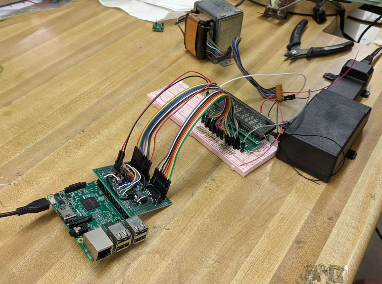
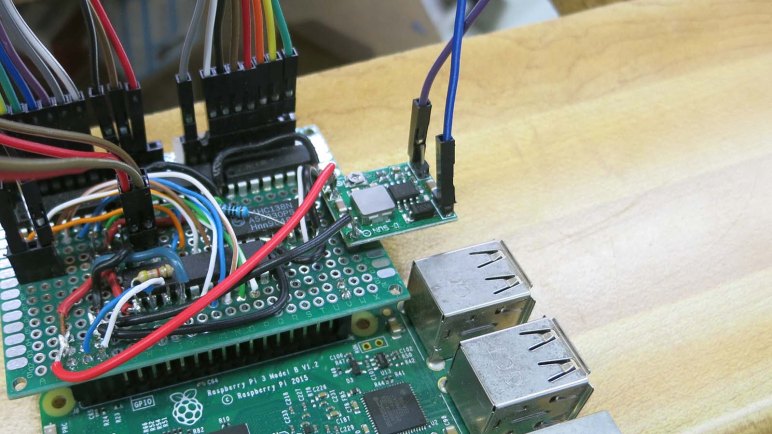
Since this was the first time Emily and I built something to light up a VFD (vacuum fluorescent display) we expected things to go wrong. Given this expectation, I wanted to be able to easily and rapidly iterate through different VFD patterns to pin down problems. I didn’t want to reflash the PIC every time I wanted to change a pattern, so the PIC driver code was written to accept new patterns over I2C. Almost anything can send the byte sequences necessary — Arduino, ESP32, Pi, etc — but what was handy that day was a Raspberry Pi 3 previously configured as backup Sawppy brain.

The ability to write short Python scripts to send different bit patterns turned out to be very helpful when tracking down an errant pin shorted to ground. It was much faster to edit a Python file over SSH and rerun it than it was to reflash the PIC every time. And since we’ve got it working this far, we’ll continue with this system for the following reasons:

  • The established project priority is to stay with what we’ve already got working, not get sidetracked by potential improvements.
  • Emily already had a Raspberry Pi Zero that could be deployed for the task. Underpowered for many tasks, a Pi Zero would have no problem with something this simple.
  • A Raspberry Pi Zero is a very limited platform and a bit of a pain to develop on, but fortunately the common architecture across all Raspberry Pi implies we can do all our work on a Raspberry Pi 3 like we’ve been doing. Once done, we can transfer the microSD into a Raspberry Pi Zero and everything will work. Does that theory translate to practice? We’ll find out!
  • We’ve all read of Raspberry Pi corrupting their microSD storage in fixed installations like this, where it’s impossible to guarantee the Pi will be gracefully shut down before power is disconnected. But how bad is this problem, really? At Maker Faire we talked to a few people who claimed the risk is overblown. What better way to find out than to test it ourselves?

On paper it seems like a Death Clock could be completely implemented in a PIC. But that requires extensive modification of our PIC code for doubious gain. Yeah, a Raspberry Pi is overkill, but it’s what we already have working, and there are some interesting things to learn by doing so. Stay the course and full steam ahead!

Death Clock Project Priorities

A project that started with exploration of VFD (vacuum fluorescent display) has evolved into a fun little project the Death Clock. Emily has an aesthetic in mind for its external enclosure and I’m fully on board with it. What’s inside the box will be dictated by the priorities we’ve agreed on. The overriding theme is focus: we’ve spent a lot of time and effort getting this far, let’s focus on putting it in use and not get distracted.

For the power system, we will use parts from the original device as we’ve done in our experiments so far. This means the original transformer, rectifier module, and several capacitors. There was the temptation to turn this into a battery-powered contraption for better portability and easier show-and-telling, but that’s a distraction today. We can tackle battery power for a future VFD project.

For the control system, we will use the exploratory control board we’ve rigged up. It is a simple circuit with an 8-bit PIC driving three ULN2003A Darlington arrays. Plus a 3-to-8 bit decoder to help with grid control. We started looking at the Microchip HV5812, a control chip designed specifically for driving VFDs, but that’s a distraction today. We can consider that chip for a future VFD project.

And finally, staying with the theme meant the simple software running on the PIC will remain as-is. I had considered adding the capability to control brightness of individual segments: fade effects are rarely seen in old VFD screens and I thought it would be a fun differentiator between old and new. But again that would be a distraction now and I can pursue it later. Potentially in conjunction with Microchip HV5812 above.

Keeping it simple and avoid feature creep. That’s the key to finishing projects instead of letting them drag on forever.

VFD Project: The Death Clock

Emily and I have been working with a VFD (vacuum fluorescent display) salvaged from a piece of old electronics. The primary objective was to demystify this now-obsolete class of technology, and with the screen lighting up to our commands, that part has been a success. But we’re not content to just leave it be… we want to do something with it. Hence the secondary objective: using this old and left-for-dead piece of technology in a “Death Clock”

What is a “Death “Clock” in this context? It’s a clock, but not a timepiece. If someone wanted a VFD clock which tells the time of day, go to a thrift store and rummage around. We didn’t go through all this work just to duplicate that! No, what we’re going to do is a quirky fun electronics project off the beaten path.

The core functionality is fairly basic, we will put a random value on this display’s time-of-day and day-of-week capability. It will do so when commanded by a touch sensor. The gag is that the clock has touched your body and sensed the time and day you will die. Completely unscientific, it’s just a fun gag. And since it’s random: if you don’t like the answer, just touch it again for another prediction on your death.

If anyone is still unsure why Emily has named her YouTube channel “Emily’s Electric Oddities“, this project should serve as prime example. Emily has done most of the electrical work and has started building prototype enclosures. My responsibility will be producing code to run this display.

Here’s Emily describing the project during episode 5 of Hackaweek Coast2Coast. (This URL should already be cued to the correct time, but if YouTube is uncooperative, skip ahead to 54:10.)

Linear CCD Sensor And Other Curiosities In A Fax Machine

For SGVHAK’s regular first Thursday of the month meeting for June, Emily brought in an old fax machine abandoned by the side of the road.

The plastic enclosure yellowing from age is not a surprise, but its heft was: it was far heavier than it looked. Judging by the collection of debris this machine had gathered, it had been left outdoors for some time. It was not a surprise when it failed to power on. Which is fine as we had no use for a fax machine and little interest in fixing it, but we were curious what was inside one of these anachronisms.

Most of this device’s mass came from a single beefy cast aluminum frame inside the machine. Select portions have been machined to precise tolerances. Why was this necessary? Emily hypothesized the robust frame was necessary to hold optical scanning components in precise alignment. The optical path was more complex than we had expected. Illumination came from a wide LED strip sitting under what looks like a glass rod slice lengthwise. It began to emit visible yellow-green light at roughly 15 volts (while drawing less than 200mA) and we cranked it as high as 20 volts (just under 500mA) but no further as we didn’t know the strip’s limits.

That light bounced off a few front surface mirrors before reaching the document, whose reflected light is picked up by yet more mirrors and finally a lens assembly that focused onto a sensor. A web search for TCD102D only found the first page of this device’s data sheet. But it was enough to tell us it was a line of 2048 photodiodes designed specifically for this purpose of scanning a line of a document scrolling past sensor optics.

For the output side of this device, there was a roll of thermal paper and a thermal image print head that worked much like the sensor in reverse: a line that heats a sheet of paper rolling past it to create an image. Digging below them both, we find the mechanical pieces making paper scroll. There was a stepper motor driving rollers for source document, and another stepper motor driving rollers feeding thermal paper for output.

Beyond the two stepper motors, few components had prospect for reuse though some (like the front surface mirrors) were kept for novelty. Unfortunately this disassembly also evicted an insect from its now-demolished home.

The biggest win was a lens assembly that formerly sat in front of the linear CCD. It has the right optical properties to be used as a small macro lens for an equally small cell phone camera. Emily plans to design and 3D print a bracket to hold this lens at the proper location and distance so we should see more close-up shots of small electronics components in the future.

Sawppy Cleanup After Maker Faire Bay Area 2019

Sawppy had a successful appearance at Maker Faire Bay Area 2019, where the two major novelties were an impromptu raincoat and an emergency steering servo replacement. Once Sawppy was home, though, there were a few cleanup and maintenance items before Sawppy is ready for the next event.

First of all, Sawppy’s wheels are filthy after running around San Mateo Event Center over the course of Maker Faire. There was mud, there was dirt, spilled coffee, dropped popsicles, and rain making all of those problems both better (washing off larger chunks) and worse (spread a thin layer across entire circumference.) Like what happened after Downtown LA Mini Maker Faire, Sawppy needed to kick off all six shoes and give them a nice long soak in chlorine-enhanced water. An retired toothbrush was used to scrub each wheel of dirt particles.  But despite the brushing and the chlorine, Sawppy’s wheels get a little dirtier with every public event. I’m not terribly concerned about this cosmetic aspect, as long as the physical mechanical capabilities are not degraded by worn grousers on the wheels.

Secondly, we have a mechanical issue to investigate. The left rear wheel is now freewheeling instead of helping to propel the rover. This was discovered late Maker Faire Sunday. At that point Sawppy still had to attend Oshpark’s Bring-a-Hack at BJ’s Restaurants, but Sawppy would spend most of that event standing up on a table. So I decided to postpone dealing with that issue until later… now is later! This turned out to be the servo horn screw backing out, allowing the servo horn to slide off that servo’s output shaft. There seems to be some minor damage from chewed up teeth, but a quick test indicates there’s enough remaining to transmit power so Sawppy should be fine.

And finally, we found another consequence of a rainy Maker Faire: Sawppy’s steel drive shafts have started to rust. This seems to have made wheel removal much more difficult so I should investigate rust removal and prevention before reassembling everything.

Sawppy Emergency Field Repair at Maker Faire Bay Area 2019: Steering Servo

Taking Sawppy to Maker Faire Bay Area 2019 was going to be three full days of activity, more intense than anything I’ve taken Sawppy to before. I didn’t think it was realistic to expect a completely trouble free weekend and any brea7kdowns will be far from my workshop so I tried to anticipate possible failures and packed accordingly.

Despite my worries, the first two days were uneventful. There was a minor recurring problem with set screws on shafts coming loose despite Loctite that had been applied to the threads. I had packed the appropriate hex wrench but neglected to pack Loctite. So I could tighten set screws back down, but lacking Loctite I had to do it repeatedly. Other than that, Friday was completely trouble-free, and Saturday rain required deployment of Sawppy’s raincoat. But Sawppy got tired by Sunday morning. Driving towards Dean Segovis’ talk, I noticed Sawppy’s right front corner steering angle was wrong. At first I thought it was just the set screw again but soon I realized the problem was actually that the servo would turn right but not left.

With the right-front wheel scraping along the floor at the wrong angle, I drove Sawppy to a clearing where I could begin diagnosis. (And sent call for help to Emily.) The first diagnostic step was pushing against the steering servo to see how it pushes back. During normal operation, it would fight any movement off of its commanded position. With the steering behavior I witnessed, I guessed it’ll only fight in one direction but not another. It didn’t fight in either direction, as if power was off. Turns out power was off: the fuse has blown.

I replaced the fuse, which immediately blew again. Indicating we have a short circuit in the system. At this point Emily arrived on scene and we started methodically isolating the source of the short. We unplugged all devices the drew power: router, Pi, and all servos. We inserted third fuse, powered on, and started testing.

Sawppy dead servo 29

We connected components one by one, saving the suspected right-front servo for last. Everything was fine until that suspected servo was connected, confirming that servo has failed short. Fortunately, a replacement servo is among the field repair items I had packed with me, so servo replacement commenced. When the servo was removed I noticed the steering coupler had cracked so that had to be replaced as well.

Using a spare BusLinker board and the Dell Inspiron 11 in my backpack, I assigned the serial bus ID of my replacement servo to 29 to match the failed front right steering servo. Then I pulled out a servo shaft coupler from the field repair kit and installed that on my replacement servo. We performed a simple power-on test to verify the servo worked, plugged everything else back in, and Sawppy was back up and running.

Flagship Maker Faires May Be Over But Making Will Not Stop

When call for makers opened up for Maker Faire Bay Area 2019, I had not planned to apply because any trip to the San Francisco Bay Area is an expensive proposition. But with encouragement from friends, I applied Sawppy and was accepted. I had a great time at the original and still flagship Maker Faire! The fantastic experience in San Mateo certainly made the dent in my personal finances easier to bear. But today we received sad news, something we heard whispers about before the event turned out to be true: Maker Media, the company behind Maker Faire, is in a state of insolvency.

While the company still technically exists and restructuring, the general trends that led to this point are undeniable: dropping attendance and sponsorship meant revenue is down, while expenses of operating in the Bay Area have continued to grow. There’s no corporate restructuring that will change any of those inconvenient trends. Maker Faire Bay Area 2020 (and beyond) are unlikely to happen.

People are understandably sad, and I share the feeling. But there are also people who declare this the end of the maker movement and I vehemently disagree. What we’ll lose is a commercial entity that sought to make a business out of organizing and channeling maker energy. It is an important and useful part, but not nearly the whole, of the maker community. Sure, it was great to have a concentrated focus of this energy in San Mateo for a single weekend, but that energy still exists and will find other channels of expression. Maker Media had already successfully franchised the concept out to many non-Flagship Maker Faires around the world, something they hoped could continue. But even if that could no longer be organized under a centralized Make banner, makers will continue to gather under various different names.

Creative resourceful problem-solving ingenuity is the mark of a true maker. The loss of a corporate entity will not change that. We lost a fantastic place to congregate but that is all. We are not going anywhere.

Unity 3D Editor for Ubuntu Is Almost Here

So far I’ve dipped my toes in the water of reinforcement learning, reinstalled Ubuntu and TensorFlow, and looked into Unity ML-Agents. It looks like I have a tentative plan for building my own reinforcement learning agents trained with TensorFlow in an Unity 3D environment.

There’s one problem with this plan, though: I have GPU-accelerated TensorFlow running in Ubuntu, but today Unity editor only supports MacOS and Windows. If I wanted to put them all together, on paper it means I’d have to get Nvidia GPU support up and running on my Windows partition and take on all the headaches that entails.

Thankfully, I’m not under a deadline to make this work immediately, so I can hope that Unity brings their editing and creation environment to Ubuntu. The latest preview build was released only a few days ago, and they expected that Linux will be a fully supported operating system for Unity Editor by the end of the year.

I suspect that they’ll be ready before I am, because I still have to climb the newcomer learning curve of reinforcement learning. I first have to learn the ropes using prebuilt OpenAI environments. It’ll be awhile before I can realistically contemplate designing on own agents and simulation environments.

Once I reach that point I hope I will be able to better evaluate whether my plan will actually work. Will Unity ML-Agents work with GPU-accelerated TensorFlow running in a Docker container on Ubuntu? I’ll have to find out when I get there.

Adventures Installing GPU Accelerated TensorFlow On Ubuntu 18.04

Once the decision was made to move to ROS 2, the next step is to upgrade my Ubuntu installation to Ubuntu Bionic Beaver 18.04 LTS. I could upgrade in place, but given that I’m basically rebuilding my system for new infrastructure I decided to take this opportunity to upgrade to a larger SSD and restart from scratch.

As soon as my Ubuntu installation was up and running, I immediately went to revisit the most problematic portion of my previous installation: the version-matching adventure to install GPU-accelerated Tensorflow. If anything goes horribly wrong, this is the best time to flatten the disk and try until I get it right. As it turned out, that was a good call.

Taking to heart the feedback given by people like myself, Google has streamlined TensorFlow installation and even includes an option to run within a Docker container. This packages all of the various software libraries (from Nvidia’s CUDA Toolkit to Google’s TensorFlow itself) into a single integrated package. This is in fact their recommended procedure today for GPU support, with the words:

This setup only requires the NVIDIA GPU drivers.

When it comes to Linux and specialty device drivers, “only” rarely actually turns out to be so. I went online for further resources and found this page offering three options for installing Nvidia drivers on Ubuntu 18.04. Since I like living on the bleeding edge and have little to lose on a freshly installed disk, I tried the manual installation of Nvidia driver files first.

It was not user friendly, the script raised errors that pointed me to log file… but the log file did not contain any information I found relevant for diagnosis. On a lark (again, very little to lose) I selected “continue anyway” options for the process to complete. This probably meant the installation has gone off the rails, but I wanted to see what I end with. After reboot I can tell my video driver has been changed, because it only ran on a single monitor and had flickering visual artifacts.

Well, that didn’t work.

I then tried to install drivers from ppa:graphics-drivers/ppa but that process encountered problems it didn’t know how to solve. Not being familiar with Ubuntu mechanics, I only had approximate understanding of the error messages. What it really told me was “you should probably reformat and restart now” which I did.

Once Ubuntu 18.04 was reinstalled, I tried the ppa:graphics-drivers/ppa option again and this time it successfully installed the latest driver with zero errors and zero drama. I even maintained the use of both monitors without any flickering visual artifacts.

With that success, I installed Docker Community Edition for Ubuntu followed by Nvidia container runtime for Docker, both of which installed smoothly.

Nvidia docker

Once the infrastructure was in place, I was able to run a GPU-enabled TensorFlow docker containers on my machine, executing a simple program.

TensorFlow test

This process is still not great, but at least it is getting smoother. Maybe I’ll revisit this procedure again in another year to find an easier process. In the meantime, I’m back up and running with latest TensorFlow on my Ubuntu 18.04.

First ROS 2 LTS Has Arrived, Let’s Switch

Making a decision to go explore the less popular path of smarter software for imperfect robot hardware has a secondary effect: it also means I can switch to ROS 2 going forward. One of the downsides of going over to ROS 2 now is that I lose access to the vast library of open ROS nodes freely available online. But if I’ve decided I’m not going to use most of them anyway, there’s less of a draw to stay in the ROS 1 ecosystem.

ROS 2 offers a lot of infrastructure upgrades that should be, on paper, very helpful for work going forward. First and foremost on my list is the fact I can now use Python 3 to write code for ROS 2. ROS 1 is coupled to Python 2, whose support stops in January 2020 and there’s been a great deal of debate in ROS land on what to do about it. Open Robotics has declared their future work along this line is all Python 3 on ROS 2. So the community has been devising various ways to make Python 3 work on ROS 1. Switching to ROS 2 now let’s me use Python 3 in a fully supported manner, no workarounds necessary.

And finally, investing in learning ROS 2 now has a much lower risk of having that time be thrown away by a future update. ROS 2 Dashing Diademata has just been released, and it is the first longer term service (LTS) release for ROS 2. I read this as a sign that Open Robotics is confident the period of major code churn for ROS 2 is coming to an end. No guarantees, naturally, especially if they learn of something that affects long term viability of ROS 2, but the odds have dropped significantly with evolution over the past few releases.

The only detraction for my personal exploration is the fact that ROS 2 has not yet released binaries for running on Raspberry Pi. I could build my own Raspberry Pi 3 version of ROS 2 from open source code, but I’m more likely to use the little Dell Inspiron 11 (3180) I had bought as candidate robot brain. It is already running Ubuntu 18.04 LTS on an amd64 processor, making it a directly supported Tier 1 platform for ROS 2.

Let’s Learn To Love Imperfect Robots Just The Way They Are

A few months ago, as part of preparing to present Sawppy to the Robotics Society of Southern California, I described a few of the challenges involved in putting ROS on my Sawppy rover. That was just the tip of the iceberg and I’ve been thinking and researching in this problem area on-and-off over the past few months.

Today I see two divergent paths ahead for a ROS-powered rover.

I can take the traditional route, where I work to upgrade Sawppy components to meet expectations from existing ROS libraries. It means spending a lot of money on hardware upgrades:

  • Wheel motors that can deliver good odometry data.
  • Laser distance scanners faster and more capable than one salvaged from a Neato vacuum.
  • Depth camera with better capabilities than a first generation Kinect
  • etc…

This conforms to a lot of what I see in robotics hardware evolution: more accuracy, more precision, an endless pursuit of perfection. I can’t deny the appeal of having better hardware, but it comes at a steeply rising cost. As anyone dealing with precision machinery or machining knows, physical accuracy costs money: how far can you afford to go? My budget is quite limited.

I find more appeal in pursuing the nonconformist route: instead of spending ever more money on precision hardware, make the software smarter to deal with imperfect mechanicals. Computing power today is astonishingly cheap compared to what they cost only a few years ago. We can add more software smarts for far less money than buying better hardware, making upgrades far more affordable. It is also less wasteful: retired software are just bits, while retired hardware gather dust sitting there reminding us of past spending.

And we know there’s nothing fundamentally wrong with looking for a smarter approach, because we have real world examples in our everyday life. Autonomous vehicle research brag about sub-centimeter accuracy in their 3D LIDAR… but I can drive around my neighborhood without knowing the number of centimeters from one curb to another. A lot of ROS navigation is built on an occupancy grid data structure, but again I don’t need a centimeter-aligned grid of my home in order to make my way to a snack in the kitchen. We might not yet understand how it could be done with a robot, but we know the tasks are possible without the precision and accuracy demanded by certain factions of robotics research.

This is the path less traveled by, and trying to make less capable hardware function using smarter software would definitely have their moments of frustration. However, the less beaten path is always a good place to go looking for something interesting and different. I’m optimistic there will be rewarding moments to balance out those moments of frustration. Let’s learn to love imperfect robots just the way they are, and give them the intelligence to work with what they have.

An Unsuccessful First Attempt Applying Q-Learning to CartPole Environment

One of the objectives of OpenAI Gym is to have a common programming interface across all of its different environments. And it certainly looks pretty good at the surface: we reset() the environment, take actions to step() through it, and at some point we get True as a return value for the done flag. Having a common interface allows us to use the same algorithm across multiple environments with minimal modification.

But “minimal” modification is not “zero” modification. Some environments are close enough that no modifications are required, but not all of them. Sometimes an environment is just not the right fit for an algorithm, and sometimes there are important details which differ from one environment to another.

One way environments differ is in different type of spaces. An environment has two: an observation_space that describes the observed state of the environment, and an action_space that outlines valid actions an agent may choose to take. They change from one environment to another because they tend to have different observable properties and different actions an agent can take within them.

As an exercise I thought I’d try to take the simple Q-Learning algorithm demonstrated to solve the Taxi environment, and slam it on top of CartPole just to see what happens. And to do that, I had to take CartPole‘s state which is an array of four floating point numbers and convert it into an integer suitable for an array index.

As an naive approach, I’ll slice up the space into discrete slices. Each of four numbers will be divided into ten bins. Each bin will correspond to a single digit zero to nine, so the four numbers will be composed into a four digit integer value.

To determine size of these bins, I executed 1000 episodes of the CartPole simulation while taking random actions via action_space.sample(). The ten bins are evenly divided between maximum and minimum values observed values in this sample run, and Q-learning is off and running… doing nothing useful.

As shown in plot above, reward function is always 8, 9, 10, or 11. We never got above or below this range. Also, out of 10000 possible states, only about 50 were ever traversed.

So this first naive attempt didn’t work, but it was a fun experiment. Now the more challenging part: figuring out where it went wrong, and how to fix it.

Code written in this exercise is available here.


Taking First Step Into Reinforcement Learning with OpenAI Gym

The best part about learning a new technology today is the fact that, once armed with a few key terminology, a web search can unlock endless resources online. Some of which are even free! Such was the case after I looked over OpenAI Gym on its own: I searched for an introductory reinforcement learning project online and found several to choose from. I started with this page which uses the “Taxi” environment of OpenAI Gym and, within a few lines of Python code, implemented basic Q-Learning agent that can complete the task within 1000 episodes.

I had previously read the Wikipedia page on Q-Learning, but a description suitable for an encyclopedia entry is not always straightforward to put into code. For example, Wikipedia described learning rate is a value from 0 to 1 plus what it means when it is at the extremes of 0 or 1. But it doesn’t give any guidance on what kind of values are useful in real world examples. The tutorial used 0.618 and while there isn’t enough information on why that value was chosen, it served as a good enough starting point. For this and more related reasons, it was good to have a simple implementation.

After I got it running, it was time to start poking around to learn more. The first question was how fast the algorithm learned to solve the problem, and for that I wanted to plot the cumulative evaluation function reward against iterations. This was trivial with help of PyPlot and I obtained the graph at the top of this post. We can see a lot of learning progress within the first 100 episodes. There’s a mysterious degradation in capability around 175th episode, but the system mostly recovered by 200. After that, there were diminishing returns until about 400 and the agent made no significant improvements after that point.

This simple algorithm used an array that could represent all 500 states of the environment. With six possible actions, it was an array with 3000 entries initially filled with zero. I was curious how long it took for the entire problem space to be explored, and the answer seems to be roughly 50 episodes before there were 2400 nonzero entries and it never exceeded 2400. This was far faster than I had expected to take to explore 2400 states, and it was also a surprise that 600 entries in the array were never used.

What did those 600 entries represent? With six possible actions, it implies there are 100 unreachable states of the environment. I thought I’d throw that array into PyPlot and see if anything jumped out at me:

Taxi Q plotted raw

My mind is at a loss as to how to interpret this data. But I don’t know how important it is to understand right now – this is an environment whose entire problem space can be represented in memory, using discrete values, and these are luxuries that quickly disappear as problems get more complex. The real world is not so easily classified into discrete states, and we haven’t even involved neural networks yet. The latter is referred to as DQN (Deep Q-learning Network?) and is still yet to come.

The code I wrote for this exercise is available here.

Quick Overview: OpenAI Gym

Given what I’ve found so far, it looks like Unity would be a good way to train reinforcement learning agents, and Gazebo would be used afterwards to see how they work before deploying on actual physical robots. I might end up doing something different, but they are good targets to work towards. But where would I start? That’s where OpenAI Gym comes in.

It is a collection of prebuilt environments that are free and open for hobbyists, students, and researchers alike. The list of available environments range across a wide variety of problem domains – from text-based activity that should in theory be easy for computers, to full-on 3D simulations like what I’d expect to find in Unity and Gazebo. Putting them all under the same umbrella and easily accessed from Python in a consistent manner makes it simple to gradually increase complexity of problems being solved.

Following the Getting Started guide, I was able to install the Python package and run the CartPole-v0 example. I was also able to bring up its Atari subsystem in the form of MsPacman-v4. The 3D simulations used MuJoCo as its physics engine, which has a 30-day trial and after that it costs $500/yr for personal non-commercial use. At the moment I don’t see enough benefit to justify the cost so the tentative plan is to learn the basics of reinforcement learning on simple 2D environments. By the time I’m ready to move into 3D, I’ll use Unity instead of paying for MuJoCo, bypassing the 3D simulation portion of OpenAI Gym.

I’m happy OpenAI Gym provides a beginner-friendly set of standard reinforcement learning textbook environments. Now I’ll need to walk through some corresponding textbook examples on how to create an agent that learns to work in those environments.

Researching Simulation Speed in Gazebo vs. Unity

In order to train reinforcement learning agents quickly, we want our training environment to provide high throughput. There are many variables involved, but I started looking at two of them: how fast it would be to run a single simulation, and how easy it would be to run multiple simulation in parallel.

The Gazebo simulator commonly associated with ROS research projects has never been known for its speed. Gazebo environment for the NASA Space Robotic Challenge was infamous for slowing far below real time speed. Taking over 6 hours to simulate a 30 minute event. There are ways to speed up Gazebo simulation, but this forum thread implies it’s unrealistic to expect more than 2-3 times as fast as real time speed.

In contrast, Unity simulation can be cranked all the way up to 100 times real time speed. It’s not clear where the maximum limit of 100 comes from, but it is documented under limitations.md. Furthermore, it doesn’t seem to be a theoretical limit no one can realistically reach – at least one discussion on Unity ML Agents indicate people do indeed crank up time multiplier to 100 for training agents.

On the topic of running simulations in parallel, with Gazebo such a resource hog it is difficult to get multiple instances running. This forum thread explains it is possible and how it could be done, but at best it still feels like shoving a square peg in a round hole and it’ll be a tough act to get multiple Gazebo running. And we haven’t even considered the effort to coordinate learning activity across these multiple instances.

Things weren’t much better in Unity until recently. This announcement blog post describes how Unity has just picked up the ability to run multiple simulations on a single machine and, just as importantly, coordinate learning knowledge across all instances.

These bits of information further cements Unity as something I should strongly consider as my test environment for playing with reinforcement learning. Faster than real time simulation speed and option for multiple parallel instances are quite compelling reasons.


Quick Overview: Unity ML Agents

Out of all the general categories of machine learning, I find myself most interested in reinforcement learning. These problems (and associated solutions) are most applicable to robotics, forming the foundation of projects like Amazon’s DeepRacer. And the fundamental requirement of reinforcement learning is a training environment where our machine can learn by experimentation.

While it is technically possible to train a reinforcement learning algorithm in the real world with real robots, it is not really very practical. First, because a physical environment will be subject to wear and tear, and second, because doing things in the real world at real time takes too long.

For that reason there are many digital simulation environments in which to train reinforcement learning algorithms. I thought it would be an obvious application of robot simulation software like Gazebo for ROS, but this turned out to only be partially true. Gazebo only addresses half of the requirements: a virtual environment that can be easily rearranged and rebuilt and not subject to wear and tear. However, Gazebo is designed to run in a single instance, and its simulation engine is complex enough it can fall behind real time meaning it takes longer to simulation something than it would be in the real world.

For faster training of reinforcement learning algorithms, what we want is a simulation environment that can scale up to run multiple instances in parallel and can run faster than real time. This is why people started looking at 3D game engines. They were designed from the start to represent a virtual environment for entertainment, and they were built for performance in mind for high frame rates.

The physics simulation inside Unity would be less accurate than Gazebo, but it might be good enough for exploring different concepts. Certainly the results would be good enough if the whole goal is to build something for a game with no aspirations for adapting them to the real world.

Hence the Unity ML-Agents toolkit for training reinforcement learning agents inside Unity game engine. The toolkit is nominally focused on building smart agents for game non-player characters (NPC) but that is a big enough toolbox to offer possibilities into much more. It has definitely earned a spot on my to-do list for closer examination in the future.

Quick Overview: Autoware Foundation

ROS is a big world of open source robotics software development, and it’s hard to know everything that’s going on. One thing I’ve been doing to try to keep up is to read announcements made on ROS Discourse. I’ve seen various mentions of Autoware but it’s been confusing trying to figure out what it is from context so today I spent a bit of time to get myself oriented.

That’s when I finally figured out I was confused because the term could mean different things in different contexts. At the root of it all is Autoware Foundation, the non-profit organization supporting open source research and development towards autonomous vehicles. Members hail from universities to hardware vendors to commercial entities.

Autoware Foundation Banner

Under the umbrella of this Autoware Foundation organization is a body of research into self-driving cars using ROS 1.0 as foundation. This package of ROS nodes (and how they weave together for self-driving applications) is collectively Autoware.AI. Much of this work is directly visible in their main Github repository. However, this body of work has a limited future, as ROS 1.0 was built with experimental research in mind. There are some pretty severe and fundamental limitations when building applications where human lives are on the line, such as self-driving cars.

ROS 2.0 is a big change motivated by the desire to address those limitations, allow people to build robotics systems with much more stringent performance and safety requirements on top of ROS 2.0. Autoware is totally on board with this plan and their ROS 2.0-based project is collectively Autoware.Auto. It is less exploratory/experimental and more focused on working their way towards a specific set of milestones running on a specific hardware platform.

There are a few other ancillary projects all under the same umbrella working towards the overall goal. Some with their own catchy names like Autoware.IO (which is “coming soon” but it looks like a squatter has already claimed that domain.) and some without such catchy names. All of this explains why I was confused trying to figure out what Autoware was from context – it is a lot lot of things. And definitely well worth their own section of ROS Discourse.


First CTF At LayerOne 2019

The term “Capture the Flag” can mean a lot of very different things depending on context. In the context of a competition held at a computer security conference like LayerOne 2019 this past weekend, I found a technically oriented online digital scavenger hunt. There is a list of challenges, each of which starts with a clue that will lead the intrepid hunter towards an answer (“flag”) that can be submitted to increase their score.

What does it take to solve a challenge? Well, that’s entirely up to the organizers who can devise problems as simple and as difficult as they wished. I attended LayerOne last year though I did not participate in last year’s CTF. What I found everywhere else at LayerOne was a fun mix of activities that start with very beginner-friendly introductions that then climb steeply to still offer a challenge to longtime veterans.

It turns out their CTF is no different. There was one very beginner-friendly challenge — it was literally a reward for reading the hint and following instructions, no technical knowledge required. [Emily] was initially intimidated but quickly contributed by employing investigation skills from her journalism background. Thanks to her skills, our CTF team did not finish dead last.

To keep things on a friendly basis of competition, the targets of investigation are explicitly listed. A security challenge of “there’s a vulnerable computer somewhere nearby, find it.” might be interesting, but a bad idea to encourage probing every computer online. It would harm other conference attendees not participating in the CTF, it would be bad for hotel infrastructure and even other guests at the hotel.

While it is possible to just have a list of computer skill challenges in a CTF, organizers usually put in a little more effort to build around a theme. This year’s LayerOne CTF was about Star Trek. From the narratives presented as clues in many challenges, down to the LCARS style user interface of the main site. While we didn’t get very far in our CTF attempt, I appreciate the effort of organizers to engage beginners. Perhaps we’ll be better equipped the next time we come across one.

Mars 2020 Rover Will Carry Sawppy’s Name

Modern advances in nonvolatile memory storage can now pack a huge amount of data in a very little space and volume. Everyday consumers can now buy a microSD card representing this advance. One of the ways NASA has taken advantage of this is offering a program where people can submit their names to be carried onboard spacecraft in the form of digital data stored on a tiny flash memory chip.

Spaceflight is still very expensive, with every gram of mass and cubic centimeter of volume carefully planned and allocated. But with flash memory chips so small and light, NASA has decided it offers enough returns on publicity to be worth carrying onboard. Such programs award social media exposure and free coverage like this very blog post!

NASA JPL’s Mars 2020 program, the most visible component of which is a not-yet-named rover successor to Curiosity, will be a participant. There will be a small flash memory chip on board with names of people who cares to submit their name via the NASA web site set up for the purpose.

I don’t care very much about having my own name on board Mars 2020, but I loved the thought of having “Sawppy Rover” as one of the names on board that actual rover heading to Mars. I’ve submitted Sawppy’s name so hopefully a few bits of digital data representing Sawppy will accompany Mars 2020 to and travel across Martial terrain.

Slowing Sawppy Response For Smoother Driving

When I first connected my cheap joystick breakout board from Amazon, its high sensitivity was immediately apparent. Full range of deflection mapped to a very small range of physical motion. It was very hard to hold a position between center and full deflection. I was concerned this would become a hindrance, but it wasn’t worth worrying about until I actually got everything else up and running. Once Sawppy was driving around on joystick control, I got my own first impressions. Then in the interest of gathering additional data points, I took my rover to a SGVHAK meet to watch other people drive Sawppy with these super twitchy controls.

These data points agree: Sawppy’s twitchy controls are problematic to drive smoothly and it’s actually running between points fast enough for me to be worried about causing physical damage.

There were two proposed tracks to address this:

First thought was to replace the cheap Amazon joystick module with something that has a larger range of motion allowing finer control. [Emily] provided a joystick module salvaged from a remote control aircraft radio transmitter. Unlike arcade game console joysticks which demand fast twitch response, radio control aircraft demands smoothness which is what Sawppy would appreciate as well. The downside of using a new joystick module is the fact I would have to design and build a new enclosure for it, and there wasn’t quite enough time.

So we fell back to what hardware projects are always tempted to do: fix the problem in software. I modified the Arduino control code to cap the amount of change allowed between each time we read joystick values. By dampening the delta between each read, Sawppy became sluggish and less responsive. But this sluggishness also allowed smoother driving which is more important at the moment so that’s the software workaround in place for Maker Faire.

This code is currently in Sawppy’s Github repository starting with this code change and a few fixes that followed.