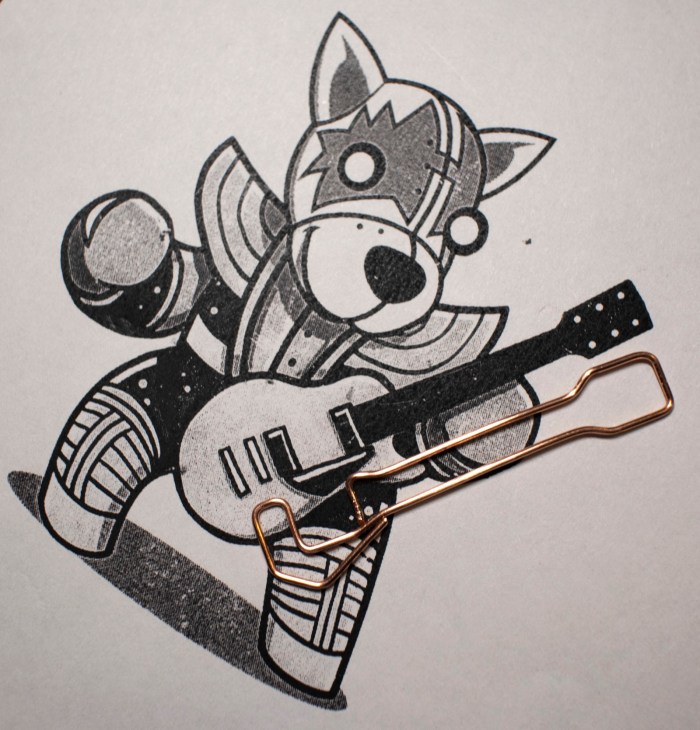
It’s good to have grand long term projects like Sawppy, but sometimes it’s nice to take a side trip and bang out a quick fun project. The KISS Tindies were originally supposed to be such a project but grew beyond its original scope. Today’s project had to be short by necessity. At less than 30 minutes, it’s one of my shortest projects ever.
The motivation for this project was an office party, but I didn’t know what the crowd was going to be like. My fallback outfit for such unknown is a long sleeved dress shirt and a sport jacket. If it turns out to be formal, I’ll be under-dressed but at least I’ll have a jacket on. If it turns out to be semi-formal I should fit in. If it is casual, I can take off the jacket. But these are people in the electronics industry, so there’s a chance I will find a room full of people wearing flashing LEDs. I decided, less than an hour before I had to leave, instead of my usual necktie I’m going to substitute a little bit of LED bling of my own.
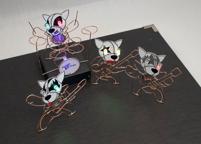
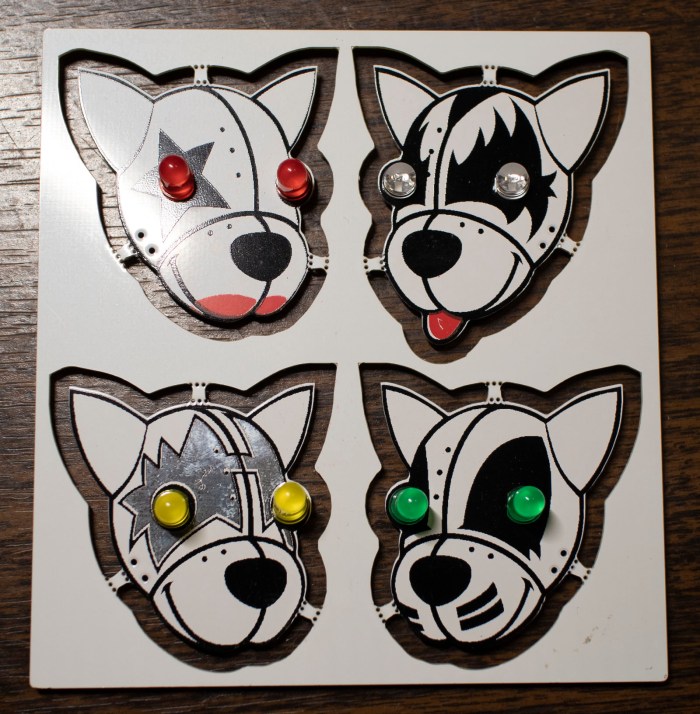
The objective is to take the same self-blinking LEDs I used on my KISS Tindies and install them under my shirt collar. Since these LEDs can be obnoxiously bright (especially in dark rooms) the light will be indirect, bouncing off fabric underneath my collar. This way I don’t blind whoever I’m trying to hold a conversation with.
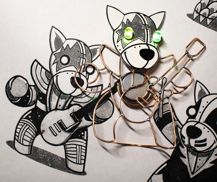
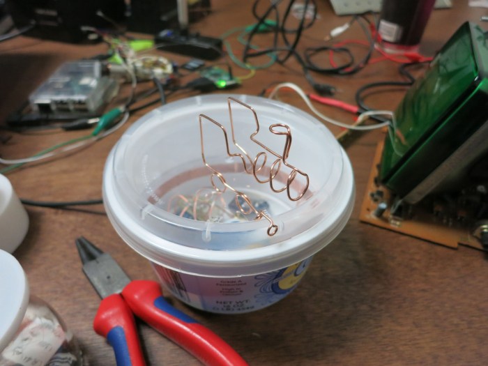
When I bought the self-blinking LEDs for the KISS Tindies project, I bought a bag of 100 so there’s plenty left to play with. For a battery holder I’ll use the same design I created for the Tindies out of copper wire. There’s no time to 3D print a structure, so I’m just going to use paper. Copper foil tape will form circuitry on that sheet of paper. Here’s the initial prototype. I folded the paper in half to give it more strength. I had also cut out a chunk of paper to help the battery holder stay in place.
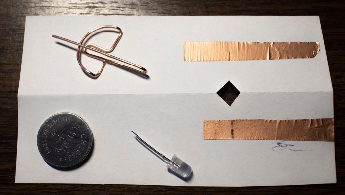
Assembling these parts resulted in a successfully blinking LED and good enough to proceed.

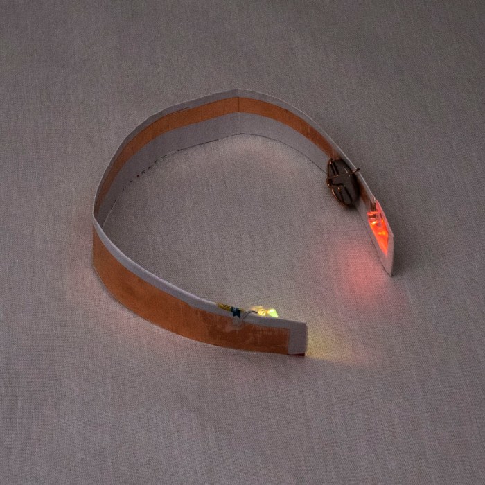
The final version used a longer sheet of paper. I measured my shirt collar and cut a sheet of paper so the ends would sit roughly 3mm inside the collar. This was longer than a normal sheet of paper so I had to pull a sheet of legal size paper out of my paper recycle bin. I think it was the legal disclosure form for a pre-approved credit card offer.
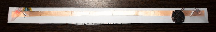
The LEDs sit a few centimeters inside the paper’s edge. The other side of the paper had extra copper tape to shield the light from shining through. I wanted the light to reflect inside my collar, not show through it. The first test showed a few circular spotlights on my shirt, so I added a sheet of Scotch tape to diffuse light. Once I was happy with the layout of this contraption, I soldered all components to copper foil for reliability.
Less than 30 minutes from start to finish, I had a blinky LED accessory for my shirt.

As it turned out, there was only one other person wearing electronics in the form of some electroluminescent wire. My blinky LED collar was more subtle about announcing itself, but they were noticed by enough people to make me happy.
(Cross-posted to Hackaday.io)


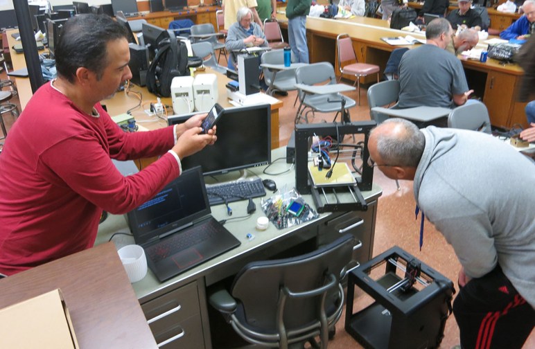


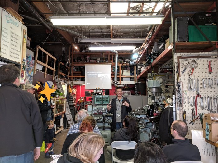
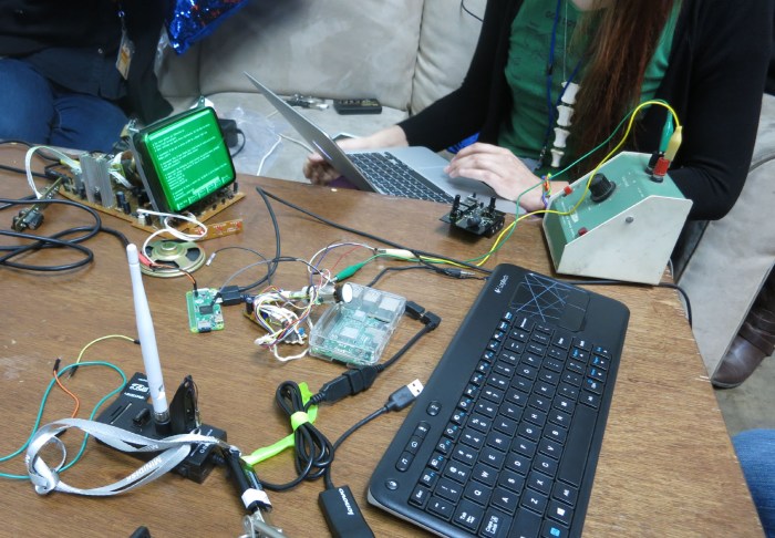


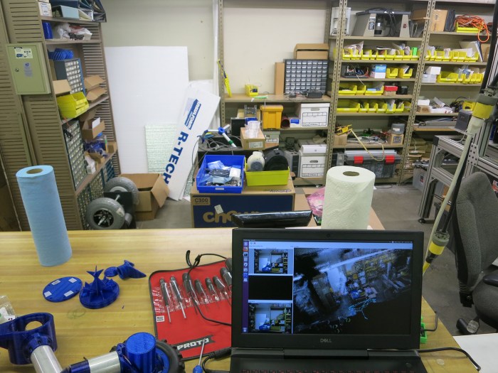
 The table started the day empty, and there was a time when it was populated by scattered stickers, but towards the evening it became an electronics workshop. Here we can see multiple simultaneous projects underway.