Chair Mounted Mouse Buttons

I was motivated by more than idle curiosity when I took apart my old Logitech M570 wireless trackball. I also wanted to use it to prototype an idea. Years of computer use has taken its toll on my body, one of them being RSI (repetitive stress injury) to my wrists. Clicking a mouse button with my index finger is an action that quickly leads to a tingling sensation and if I continue, pain. This was part of the reason I prefer trackballs that let me click with my thumb, but what I really want to do is transfer that workload to an entirely different part of my body.

Which is where the retired wireless trackball came into the picture. The ergonomics of this design preserved the use of index finger for button clicks, something I explicitly did not want. But it is still a perfectly functional computer pointing device, so I took it apart hoping to find electrical contacts I could utilize for different mouse click options. I was happy to find that the primary (left click) and secondary (right click) buttons were large through-hole Omron switches, with easily solderable pins accessible from the bottom of the circuit board. Probing with my meter found their “Common” pin are both connected in parallel. I see traces going to their center pin, which is Normally Open. The third pin is Normally Closed (with Common) and appears unused in this device.

To experiment with different ways to left- and right-click, I soldered three wires: red wire went to the common pin shared between both switches. Blue wire went to the left-click button’s “Normally Open” pin, and yellow went to the right-click button’s Normally Open pin.

Powering the device back up, I confirmed that connecting blue to red wire would result in a left-click, and connecting yellow wire to red would result in a right-click. I closed the trackball back up, routing these wires through the hole left by removing the physical plastic pieces for left- and right-clicks. These three wires were crimped into a JST-SM wire-to-wire connector (*) so I could experiment with different button implementations.

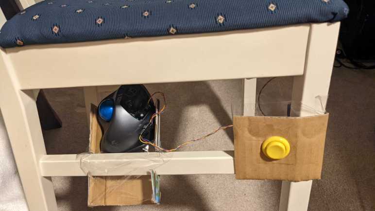
The first prototype is to mount large durable arcade machine style buttons to the left and right legs of my chair. This picture shows the right side, with a yellow button corresponding to right-click yellow wire. This allows me to perform mouse clicks by using my legs, pressing my calf against the button. I have no idea how well this would work (if at all) so I used cardboard to hold the button in this first draft. And thanks to the fact this trackball is wireless, I could still move the chair around without worry of tangling or damaging a wire.

The first few attempts to use this felt really strange, but that’s fine. Clicking a mouse button is such a habitual task that I expect a period of acclimation even in the best of circumstances. And this doesn’t really get in the way of anything, because I could continue using my desktop trackball. I will leave it installed for a few weeks to see if I’ll adapt to it over time. One thing is sure, though, moving my legs to click these buttons would not put any stress my wrist.

Bedside Fan and Light V2

I took apart the Asiahorse Magic-i 120 V2 control hub and remote because I didn’t need them anymore: I could control its trio of fans with my own circuit board. How shall I wield such power? It was fun playing with 3D coordinate mapping with a Pixelblaze, but my most immediate need is a lot less exciting: combination bedside fan and light to replace my first bedside fan project. (Which didn’t have a light.)

For such a simple use, the power of a Pixelblaze is overkill. So, my board was modified to use an ESP8266 (Wemos D1 Mini module) as its brain, running ESPHome for integration with Home Assistant. In the Pixelblaze demo, the fans were always on. Now they will be controlled by that ESP8266 as well.

I’m still not settled enough on the idea to spend the time designing and 3D printing a proper frame, but at least I’ve put a bit more effort into this cardboard creation. I’m reusing a corner of a Newegg shipping box (I think it was the very box used to ship the Asiahorse fan bundle) and I’ve turned it inside out so at least I don’t have to stare at the Newegg logo every time I’m in bed.

Three large holes, one per fan, was cut from that cardboard for airflow. Twelve more holes, four per fan, were drilled into the cardboard for fan mounting screws. The physical assembly came together quickly, but there were a few more hiccups.

First problem was that FastLED, the addressable LED Arduino library used by ESPHome, is not compatible with the latest Arduino 3 framework at the time of this writing. Relevant ESPHome documentation page listed the issues as 1264 and 1322 filed against FastLED Github repository. Until they are resolved, ESPHome offers a workaround for compiling against Arduino framework 2.7.4. Which is what I did to run these WS2812 LEDs. For the first draft, I’m not going to use the addressable nature at all, just a single solid color. I think it would be cool to have a falling waterfall pattern on these lights, but that’ll be experimentation for later.

The second problem is that PWM control of fan speed results in an audible whine, probably an 1kHz whine which is the practical maximum speed for ESP8266 software PWM. The previous fan project removed the audible whine by adding a capacitor to smooth out voltage output. I could do that again, one capacitor per fan, but these fans run quietly enough at full speed I’m willing to skip PWM and have just on/off control.

The final problem is that I still want this fan to be responsive to temperature changes, turn itself off in the middle of the night when it got cool enough. I wasn’t happy with the TMP36 sensor I bought for the previous experiment, so now I’m going to try another sensor: the DS18B20.

Temperature Responsive Cereal Box Fan

This quick and easy project produces a quiet breeze for hot summer nights. I wanted something gentler than the fans already in the house, and I wanted it to automatically turn itself off in the middle of the night once things cooled down enough. It also let me apply lessons I’ve recently learned. Even though I’ve found that the TMP36 sensor isn’t a great fit for a ESP8266, it’s something already on hand for an ESP8266 to tell if it’s cool enough to turn the fan off.

The 3-wire fan is a PC cooling fan with a 200mm diameter, relatively large within that category. I bought it some years ago for my first Luggable PC project, it was just a bit too large for that purpose and sat idle until now. I thought about designing and 3D-printing a stand for this fan, but in the spirit of keeping things simple and quick, I mounted it in an empty cereal box instead. Cutting holes in the box to accommodate the fan took a tiny fraction of the time it would have taken to 3D-print something.

Primary air intake was the top of the box, left open.

I cut a smaller secondary air intake towards the bottom of the box, which also makes it easy to toss my control board in there and feed it power from a salvaged DC power supply. A TMP36 sensor was soldered in the farthest corner in this picture, visible sticking up vertically.

Results

Running ESPHome (YAML excerpt below) this project successfully controls fan speed via ESP8266 PWM. It was also able to read temperature via TMP36 sensor, but values were affected by ESP8266. Located 1/2 of the circuit board away plus the entire height of its legs was not enough distance from the ESP8266 heat island: temperature reading dropped noticeably whenever the fan is turning. Still, it’s enough for me to create a Home Assistant automation to turn off this fan whenever the temperature dropped below a certain threshold. Due to the heating from ESP8266, the temperature value rises a few degrees immediately after the fan was turned off. Thankfully there was no risk of system feedback oscillation, because I did not create an automation to turn the fan on — I do that manually when I’m ready for a light breeze.

This worked well sitting on my bedstand, creating a light cool breeze when I’m ready to fall asleep and turning itself off while I was asleep. But its physical footprint was a problem: it took up space that is ideally used for a bedstand light. The obvious solution was to pull some LEDs into the next version, which is an opportunity to tackle another item on my to-learn list: PC accessories with embedded RGB LEDs.


ESPHome YAML to read TMP36 temperature and fan speed every 5 minutes:

sensor:
  - platform: adc
    pin: A0
    name: "Fan Temperature"
    unit_of_measurement: "°C"
    update_interval: 1s
    accuracy_decimals: 2
    filters:
      - multiply: 100
      - offset: -50
      - sliding_window_moving_average:
          window_size: 450
          send_every: 300
          send_first_at: 15
  - platform: pulse_counter
    pin: 12
    id: fan_rpm_counter
    name: "Fan RPM"
    unit_of_measurement: "RPM"
    accuracy_decimals: 0
    update_interval: 300s
    filters:
      - multiply: 0.5 # 2 pulses per revolution

output:
  - platform: esp8266_pwm
    pin: 14
    id: fan_pwm_output
    frequency: 1000 Hz

fan:
  - platform: speed
    output: fan_pwm_output
    id: fan_speed
    name: "Fan Speed Control"

Micro Sawppy Rover Cardboard Box Testbed

Proving that I could control DRV8833 DC motor driver IC using an ESP32 was the final piece of the foundation I knew I needed before I seriously start building a micro Sawppy rover brain on an ESP32. During my development of this software, I will need a physical chassis to test code on. While I could go straight to my Micro Sawppy Beta 3 (MSB3) chassis, doing so has the risk of breaking physical robot hardware. Anything from a servo moving beyond intended limits, to embarrassing mistakes like driving the rover off the table.

A safer option is to have a representative testbed with fewer risks than a physical robot. For my original Sawppy rover, I removed all ten LX-16A serial bus servos and laid them out on a table. I found that a line of servos wasn’t very good at conveying system behavior, since I had to do some mental spatial transforms in my head to interpret those servo movements. Some bugs slipped through this process because I made mistakes in my mental visualization. From that experience I thought it would be better to have a testbed that better represented the physical layout of the rover chassis, and this is an opportunity to put that idea to the test.

In line with my recent discovery of cardboard for mockup purposes, I pulled a cardboard box from my paper recycle bin. I turned the box inside-out to give me some clean note-scribbling surfaces, plus I’m not advertising that product on this site anyway. Holes were cut in the cardboard so I could use twist ties to fasten six TT gearmotors in the same relative location as they would be on a rover. I also cut four rectangular holes for the steering micro servos. Since I cut those holes by hand, the imperfections of the manual cut gave the servos enough friction to sit in place without any fasteners.

Wires for all of these components went into the box, and small holes were cut so they could poke through to this top surface. This routing keeps all excess lengths of wire out of my way making for a neater work area. The ESP32-based control board, whatever it ends up being, should fit in the center area I kept clear for it. Excess wire isn’t the only thing I kept in the box, it was also a convenient place to store all the related auxiliary pieces related to the project. Each micro servo has a plastic bag with spare control horns as well as their mounting screws not needed for the testbed. And each gearmotor came with a wheel that’s not strictly necessary for the testbed. There’s a chance I’ll want these wheels later, to better visualize relative rotation velocity of the wheels. If that should occur I know where to find the wheels: they’re in the box!

But first I need to get started with Sawppy ESP32 software.

Jumper Wire Headaches? Try Cardboard!

My quick ESP32 motor control project was primarily to practice software development for FreeRTOS basics, but to make it actually do something interesting I had to assemble associated hardware components. The ESP32 development kit was mounted on a breadboard, to which I’ve connected a lot of jumper wires. Several went to a Segger J-Link so I had the option of JTAG debugging. A few other pins went to potentiometers of a joystick so I could read its position, and finally a set of jumper wires to connect ESP32 output signals to a L298N motor control module. The L298N itself was connected to DC motors of a pair of TT gearboxes and a battery connector for direct power.

This arrangement resulted in an annoying number of jumper wires connecting these six separate physical components. I started doing this work on my workbench and the first two or three components were fine. But once I got up to six, things to start going wrong. While working on one part, I would inadvertently bump another part which tugs on their jumper wires, occasionally pulling them out of the breadboard. At least those pulled completely free were clearly visible, the annoying cases are wires only pulled partially free causing intermittent connections. Those were a huge pain to debug and of course I would waste time thinking it was a bug in my code when it wasn’t.

I briefly entertained the idea of designing something in CAD and 3D-print it to keep all of these components together as one assembly, but I rejected that as sheer overkill. Far too complex for what’s merely a practice project. All I needed was a physical substrate to temporarily mount these things, there must be something faster and easier than 3D printing. The answer: cardboard!

I pulled a box out of my cardboard recycle bin and cut out a sufficiently large flat panel using my Canary cutter. The joystick, L298N, and TT gearboxes had mounting holes so a few quick stabs to the cardboard gave me holes to fasten them with twist ties. (I had originally thought to use zip ties, but twist ties are more easily reused.) The J-Link and breadboard did not have convenient mounting holes, but the breadboard came backed with double-sided adhesive so I exposed a portion for sticking to the cardboard. And finally, the J-Link was held down with painter’s masking tape.

All this took less than ten minutes, far faster than designing and 3D printing something. After securing all components of this project into a single cardboard-backed physical unit, I no longer had intermittent connection problems with jumper wires accidentally pulled loose. Mounting them on a sheet of cardboard was time well spent, and its easily modified nature makes it easy for me to replace the L298 motor driver IC used in this prototype.

Cardboard Absurdity: Sexy Minion

I abandoned the first draft of my cardboard Mike Wazowski for another attempt later, but I did not abandon my other Hallowing. An idea to put it to use came courtesy of Emily’s reply to my cardboard minion tweet.

This “sexy minion” is certainly not something I would have found on my own, and my initial reaction was probably what Emily intended: vaguely disturbed and resignation to the fact I can’t un-see that image.

But it’s on Twitter now, and it’s also in my brain now, and I do have an extra Hallowing on hand, so I decided to play along with the joke with a minimum-effort project. I imported the image into a photo editor and scaled it so the eye is the right size to use with a Hallowing. Fortunately it fit on a sheet of standard letter-sized paper so I didn’t have to crop any part of it off.

I tried to print it on my color inkjet printer, but that thing hasn’t printed anything in months (possibly years) so naturally its print nozzles were clogged. A standard unclog routine did not fix it and I didn’t want to spend time troubleshooting. (Remember: minimal effort.) So I printed on my monochrome laser printer and colored it in manually afterwards using markers.

Given the minimal effort I didn’t try to trace the outline curves with my new favorite cardboard tool the Canary knife, just a rectangular piece of cardboard and the marker-colorized paper taped on top. My X-Acto blade made quick work of the eyehole, and the second Hallowing was taped in place. I set it up my convertible photo studio for a quick video and threw it up on Twitter.

This silly little project couldn’t have taken more than half an hour (even less if I subtract fussing with the clogged inkjet) and it turned out to be unexpectedly (or is that disturbingly?) popular. As a result I have the sinking feeling this is not the last I’ve seen of “sexy minion”.

I also felt a bit bad that I didn’t put in the time to research where that drawing came from. It wasn’t a big deal when I thought it’d just be a throwaway joke between friends, but with thousands of views the artist’s name should have been attached. I can’t edit my original tweet, but I could at least credit the artist @nicoisesalade here:

Cardboard Companion: Mike Wazowski

My trial run using a Canary cardboard cutter was far more successful than I had expected, resulting in a little cardboard companion minion perched on my shoulder. I was extremely happy and joined this month’s (Virtual) Wearables Wednesdays event at CRASHSpace to show off my minion as a wearable electronic project. And also to thank Barb (who usually attends the event) for telling me about the Canary cutter.

Barb immediately (and correctly) recognized the minion’s eye as the Adafruit HalloWing default program. She had several sets of similar eyes on hand, some incorporated into projects, but all the units within reach came as pairs so there were no immediate advice on how to get my two units to synchronize. But by now I didn’t really want to synchronize them anyway, because that would mean taking apart my minion which I’m not ready to do just yet.

So I asked the attendees what I should do with the other eye. People started brainstorming and tossing out ideas. They were fine ideas but they didn’t capture me as much as when Liz said “Mike Wazowski”. I said “Yes!” and got started immediately while the meeting was still underway. This is falling back on old patterns, as it is pretty typical for work to happen during non-virtual Wearables Wednesdays meet.

I found a picture of Mike Wazowski on the internet and traced out a rough outline on cardboard. For the minion I wanted to keep the eyehole small so none of the electronics are visible. For Mike I thought I’d explore how things looked if the eye hole was larger.

Once I had Mike cut out and popped my second HalloWing into the eyehole, I decided I did not like how it looked. I much preferred the minion approach where the circuit board was hidden. If I wanted to build a Mike Wazowski with a properly obscured HalloWing eye hole while still maintaining proportions, I will need to cut a smaller Mike. There’s also a second reason to want a smaller Mike: this one is too wide to sit properly on my shoulder. Maybe someone with much broader shoulders can pull it off, but this Mike’s butt is too wide for me to carry around.

I will abandon this cardboard cutout and stick “try again with smaller Mike” on the to-do list. This is the beauty of experimenting with cardboard: cost of failure is low, and speed of iteration is fast. I could very quickly follow up this abandoned project with an absurd project.

A Canary Corrugated Cardboard Cutter Convert

One of the bonus motivations for building my cardboard companion minion was a test run of the Canary Corrugated Cardboard Cutter (*). After my experience in that project, I am now a big fan of this tool.

I learned of the Canary cutter via CRASHSpace, a longstanding maker community in the greater LA area. As they are on the opposing side of downtown LA it is not trivial for me to visit. But now that everything is virtual, I actually have more interaction with members of that community than I would have otherwise.

One of the recent discoveries started by watching Barb Noren‘s session “Tinkering @ Home” for Virtually Maker Faire 2020. One of the topics was their Tinkering Toolkit and the Canary cutter in that kit caught my eye. Given the popularity of home delivery in these times, many of us are going through a large number of corrugated cardboard boxes. We could throw them in the recycle bin, but Barb Noren asserts that is a waste: they are useful raw material for projects! And the Canary cutter is how reDiscover Center can set children loose on cardboard, as young as seven years old, under adult supervision.

I’ve built many projects with corrugated cardboard, using X-Acto blades for fine detail and large box cutter knives for large cuts. And yes, I’ve had my share of accidental cuts and so I was immediately interested in the idea of a much safer cutting tool. I was willing to trade off some cutting effectiveness if it would gain me more safety. And after asking Barb a few questions about it at a virtual CRASHSpace event, I ordered one of my own to try.

When my Canary cutter arrived, I saw a well built tool with a plastic handle for manipulating the metal cutting blade, which was edged with fine serrations. It looked fine but did not inspire great expectations. That attitude changed as soon as I took a test cut. I had expected the serrated teeth to tear rough edges in the cardboard, and I had expected the less-scary blade to also be less effective than a sharp blade at cutting.

I was wrong on both counts.

The Canary cutter cut through corrugated cardboard amazingly quickly, with less effort than box cutter blades, and left a pretty clean edge. Yes, if I compare it side-by-side with something cut by a sharp knife I can see a difference, but when we’re working with corrugated cardboard we’re not exactly working with precision tolerances anyway. And the serrated edge cuts enough clearance that the blade does not get stuck, which my box cutter knives tend to do. Freeing a stuck sharp knife is the major cause of my crafting injuries, so just by eliminating that scenario, things became a whole lot safer.

However, it is still a cutting knife that demands respect, as I’ve already managed to draw my own blood once. But it is much less dangerous than putting big box cutter knives in the hands of children. Since Barb’s session video, reDiscover Center has posted another video about using the Canary cutter.

I’m pretty amazed at how well the Canary cutter worked. This reduces the barrier of entry for corrugated cardboard projects in the future. As the above video stated, it is not suitable for all cuts. We’d still need to have scissors and our old friend the X-Acto blade for fine detail, but for large cuts the Canary cutter is pretty amazing. Anyone who wants to unleash their creativity on corrugated cardboard should get one. (*)

Naturally, with my hands on such a fun new tool, I didn’t stop at just one project and found another cardboard project to start on.


(*) Disclosure: As an Amazon Associate I earn from qualifying purchases.

Cardboard Companion: Minion

I’ve long admired the robot companions built by Alex Glow and Odd Jayy but never dedicated the time and effort to build a good one of my own. I still haven’t done so… but I’ve spent roughly an hour or two to build a low-effort companion out of cardboard.

This project was kicked off when I was moving a few boxes around and noticed the Hallowing I received at Supercon 2018 almost two full years ago. When I wrote about it earlier I thought it had full of promise and should be a lot of fun to play with. That is still true, it just never came to the top of my priority list. I actually have two of them now, as Emily gave me hers saying she’d never do anything with it. I said I would definitely find something fun to do but nothing had happened since.

So when I saw them again, I had an urge to do something with them right now. Today. The pair of Hallowing deserved to be dusted off, literally and figuratively. If I can’t do something unique and cool, I can at least do something to verify at least they still function.

When I plugged them into a USB power bank, they started right up. A good start!

I thought I’d use them both by following Adafruit’s instructions to synchronize two of them. Unfortunately I made a mistake somewhere and the two eyes remained stubbornly independent. So I switched to a backup plan: what do I know that has a single eye? The first one that came to my mind is a minion from the movie Despicable Me.

I made a rough sketch and cut out the shape of a minion. I wanted the minion to sit on my shoulder, so the outline was placed such that the existing fold for this box lid is roughly at the (not terribly well defined) waist of the minion. The cutting tool visible in this picture is a Canary corrugated cardboard cutter. This was my first time using it and I am now a big fan.

After I cut out the eyehole, a quick size comparison test confirmed it was in the ballpark. I decided to stop cutting at this point. A hole that’s slightly too small like this will obscure a portion of the eye, not a big deal. In contrast a hole that’s slightly too big will show the wires at the edge of this LCD module or the circuit board underneath, either of which would spoil the look and thus something I wanted to avoid.

A black marker helped make the cardboard look more like a minion.

The minion’s work overalls courtesy of blue highlighter marker.

I used cardboard to build a tripod to help the minion sit on my shoulders, but it is top-heavy with the Hallowing and prone to falling over. I decided to tape some magnets to the bottom of the minion.

Once I set the minion on my shoulder, I could install matching magnets inside my shirt. The two magnets pinch fabric of my shirt, holding the minion in place.

Voila! A low effort cardboard companion.

It only scratches the surface of what the Hallowing can do, but far better than just letting it gather dust. Will it find a place in a cooler and more sophisticated project? Check back in two years!