Slimming Down Sawppy the Rover’s Printed Suspension Parts

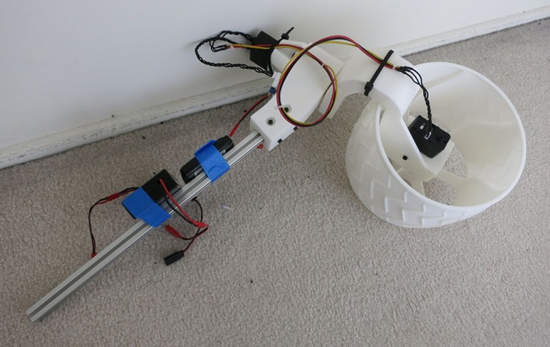
When designing Sawppy the Rover‘s rocker-bogie suspension system, I wasn’t sure how strong the plastic interconnect parts needed to be. Once I had a rocker and a bogie connected, I could put some load on it in the real world. This physical experimentation showed the first draft was overbuilt. In the interest of reducing plastic filament usage and reducing print time, let’s slim things down a bit.

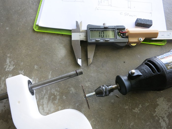
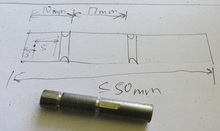
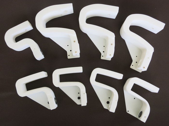
First draft interconnects held on to their aluminum extrusion beam over a distance of 50mm. This was reduced to 35mm which proved to be enough. Beyond reducing the length of extrusion bracket, the slim edition also makes the brackets thinner from 5mm to 3.5mm. Originally the 5mm thickness was intended for a 10mm M3 bolt to grab onto the extrusion tightly, but that under-estimated the thickness of our M3 nut installation tool. This oversight meant a 10mm M3 bolt hits the bottom of the rail before it can fully tighten against the bracket. By reducing to 3.5mm, we could use 8mm M3 bolts and they can tighten against the bracket without pushing against the bottom of the rail.

Shortening length from 50mm to 35mm and reducing thickness from 5mm to 3.5mm may not sound like much, but across all suspension components it cut print time and plastic usage almost by half.

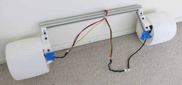
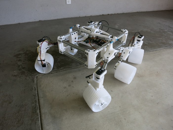
The first draft rocker-bogie suspension was not thrown away, though. It was installed on the left side of the rover, and the second draft slim edition was printed mirrored so it could be installed on the rover’s right. It makes the initial chassis asymmetric and look a bit odd, but that’s fine. We can put up with a little oddness on our rover development chassis while we fine tune and polish.

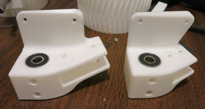
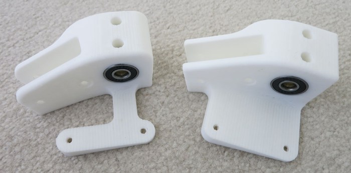
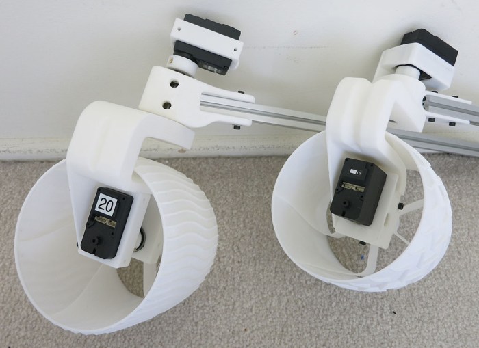
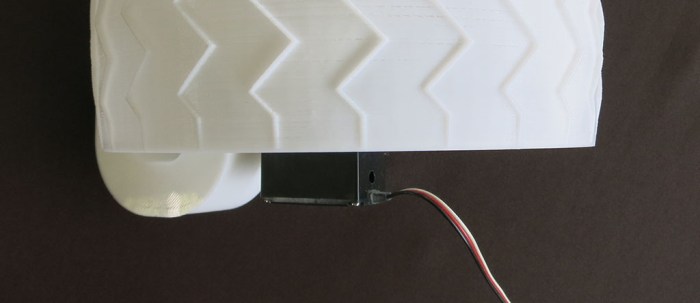
The overbuilt first draft suspension on rover’s left side was eventually replaced with slim components. Here’s a picture of the left front steering joint: overbuilt first draft on the left, slimmer second draft on the right.

Slimmer Sawppy Connectors

Stress Testing Rover Wheel To Destruction

Once Sawppy the Rover‘s wheel design was verified to work for basic operations, it’s time to push it to find its limits. The wheel is designed to be strong enough to hold up rover weight yet have flexibility to absorb shock. The shock absorption spokes tried to turn 3D printed plastic’s weakness (relative to metal) into a functional advantage instead. But plastic has its limits… how much will it take?

This was not a rigorous laboratory test. There are no instruments documenting the quantity and quality of forces involved. It was a low-tech test manually handling the wheel until something breaks. Push, prod, squeeze, twist. Level of forces applied gradually increased, venturing well beyond “normal use” levels and well into “abuse”. Eventually I tried pushing the wheel from above and, using body weight, gradually increased pressure until a loud crack was heard.

What finally gave way was one of the spokes near where it joined the wheel circumference. This joint was designed to withstand compression, which it did very well. But when the wheel is compressed along one axis, it also expands along the perpendicular axis. This joint design did not fare as well in tension. The sharp corner where the spoke meets the wheel circumference focused stress, and that’s where it broke.

Sawppy Wheel Stress Test

The little wheel held up amazingly well! The kind of abuse it withstood before it finally gave way tells us there’s a significant safety margin beyond what would be considered normal rover operations. And even given this cracked spoke, the rover wouldn’t be crippled. This wheel would still be able to support some weight until we get around to changing it out for an undamaged wheel.

Another important factor in stress tolerance is the type of material. This particular wheel was printed with Monoprice PLA. In the spectrum of 3D printable plastic PLA is considered brittle and prone to cracks like this one. Eventually, though, what ended up motivating a switch to PETG is not brittleness but heat tolerance: PLA rover wheels soften and distort when it got hot.


Sawppy the Rover Emulates Wheel of Mars 2020

While searching for references on Curiosity’s rocker-bogie suspension geometry, I came across a high-resolution CAD rendering of JPL’s upcoming Mars 2020 rover. It was a useful reference for suspension geometry as it is largely identical to Curiosity’s suspension. But there’s one very interesting change: the wheel design was noticeably different for Mars 2020.

Mars2020
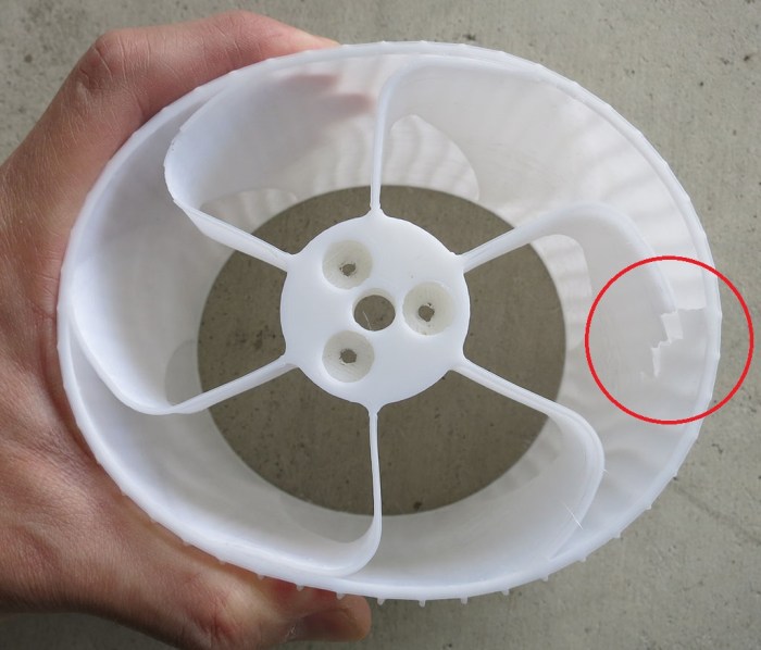
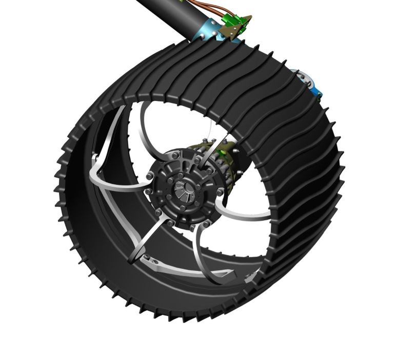
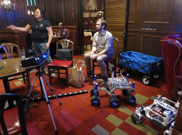
Curiosity suffered wheel damage in its travels and it’s no surprise JPL took the lessons learned and equipped their follow-up rover with a different wheel design. Aside from lessons about reliability, there are also changes made to better match the terrain this rover expects to see in its mission area. Here on Earth our cars have different tires for different environments, so a Mars rover similarly gets wheels tailored to its mission.

Performance requirements are not nearly as stringent for an earthbound rover model, so we have the freedom to adopt either design based on preference. I decided to try printing a wheel inspired by Mars 2020 rover wheel design and see how it looks.

These wheels still have the same six spokes as Curiosity wheels, each a piece of titanium curved in a way that’s not easy to duplicate in 3D printed plastic, but we can still take inspiration. The article linked above mentioned the wheel proportions are slightly different, they didn’t provide exact numbers. So we kept the spokes and the proportions and changed the wheel grousers, which are gently curved instead of zig-zagged and there are twice as many of them. (24 vs 48.)

Sawppy wheel

Once printed, we can compare the wheels side by side. Curiosity-inspired design on the left, Mars 2020-inspired design on the right. I took it around for feedback from other members of SGVHAK and the response overwhelmingly favors the new Mars 2020 inspired design. So that’s what Sawppy and Rover will roll on!

Curiosity Style vs Mars 2020 Style

Design To Ease Reusing Bearings Pressed Into 3D-Printed Parts

(Update: I’ve found a better way to recover bearings for reuse. The post below is now obsolete, but will be kept around for laughs.)

Once general suspension geometry of Sawppy the Rover had been sketched out, it’s time to start building suspension components. The general construction technique has been documented, it just takes a lot of sweating the details to make everything work together as intended. Like any design endeavor, the first draft is never quite right and every part takes a few iterations to mature.

When a 3D printed plastic part turns out to be flawed for one reason or another, the plastic is effectively lost. Many people find this wasteful, some are working to recycle the plastic in some way, but nothing practical just yet. I’m not interested in recovering the plastic right now. The bearings I had pressed into the plastic components, however, are another matter.

Unlike the plastic, the bearings are easily reusable in follow-on design iterations of the part. Since the plastic is forfeit anyway, we can cut plastic apart to recover these bearings, but such cutting has to be done carefully to avoid damaging the bearing. It would be better if we can remove bearings in a way that’s more reliable and less likely to cause damage.

To help with this process, I’ve started incorporating access holes into suspension components that are useless to the rover itself. In fact, it might be a bit detrimental by weakening the component to some degree. The purpose of these holes is to provide physical access so there’s leverage to pry these bearings loose without cutting. Here’s one of the earliest steering knuckles (right) next to a more recent iteration (left) that provides an access hole to push bearings out for reuse.

Bearing Recovery Assist

In theory, once component design is final, these holes can be deleted so I can print a seamless and full strength part. In practice, I’m probably never going to stop tinkering with the design or, even if I do, I don’t foresee throwing away a perfectly functional part purely for the sake of printing one without the access port. I may release designs without bearing recovery port for others to print, but my own rover development chassis will always be Swiss cheese.

Copying Curiosity Rover Suspension Geometry for Sawppy the Rover

Now that we have a rover wheel that can drive and steer, it’s time to figure out how all the individual wheels relate to each other. This is the most important part of making a motorized model of Curiosity Mars rover: copying its sophisticated rocker-bogie suspension system. It is critical for appearance because a huge part of Curiosity’s unique look comes from its suspension. It is equally critical for functionality, as the suspension grants Curiosity its ability to traverse rough terrain. It wouldn’t be a model of Curiosity at all without its suspension!

On the flip side, copying Curiosity’s suspension also means taking on some of the trade-offs that made sense for Mars but not for Earth. The first example is that Curiosity’s suspension had to fold up for its journey to Mars, which our rover model would not need to do.

The second example is that the rocker-bogie suspension system is most capable climbing using the bogie, which is why JPL’s Open Source Rover (and ROV-E that proceeded it) had their bogie in the front. Curiosity has its bogie in the back. I asked why Curiosity is more capable going backwards than forwards and the answer was that Curiosity must be able to back out of whatever situation it gets into. If a little rover got stuck here on Earth, we can walk over and pick it up. If Curiosity got stuck on Mars, the nearest tow truck is many millions of miles away.

There are more sacrifices of similar nature, but since the model is intended to be mechanically faithful, we’re going to accept all these downsides of copying the design. So, onward to the internet to find references! While there are many pictures of Curiosity rover, it was unexpectedly difficult to get an isometric three-view drawing. The best I could find was in a JPL presentation MSL Rover Actuator Thermal Design (08-0699.pdf) for Spacecraft Thermal Control Workshop 2008. Page 6 of this slide deck had a good side view of Curiosity with major dimensions labeled.

This diagram became my primary reference for Sawppy the Rover. I copied it into Onshape as an image overlay and drew Sawppy’s component layout on top. This gave us a very high fidelity in the side view, unfortunately no similar top view diagrams were found so I had to guess using less precise images as reference. After some fiddling, I got a reasonable facsimile of Curiosity rover. Compare the rough sketch in Onshape with a JPL official photograph of Curiosity.


RockerBogieLayout

Comparison: Curiosity rover at JPL Mars Yard

Cropped Curiosity rocker bogie reference


Pros and Cons of Common Steel Shaft for Sawppy the Rover

Steer vs Drive Shaft

After the decision was made to use a common servo mounting bracket for both driving and steering Sawppy the Rover, the obvious next question is: why not use a common shaft design as well?

Consolidating to a common shaft design reduces the number of unique parts to keep track of, and has the potential to make fabrication easier. This reasoning made sense for servo brackets, who benefits from this commonality with no downsides.

Sadly, in the case of these steel shafts, there are functional downsides.

The servo side is not an issue. Since all servos use the same mounting bracket and coupler, the dimensions are obviously identical on that front.

The output side aren’t common and there are some minor reasons why. For the steering shaft, output section length matches the thickness of the steering knuckle. The driving shaft’s output section is longer, because it has to fit into the wheel hub as well as extending into the wheel itself for structural support. An experiment with a shortened shaft showed this length is an important guard against wheel torsional flex so we shouldn’t shorten it. Therefore a common shaft demands that the steering knuckle needs to be thicker where it meets the shaft. If we keep the existing mating location and extend shaft downwards, it reduces wheel clearance. If we move the mating location upwards, it increases the mechanical leverage of wheel load acting on the steering joint making its job harder. Both of these options are undesirable.

But the deal-breaker is the section in the middle – where the shaft is supported by a pair of bearings. The drive shaft has a short section in order to make room for the servo to be completely enclosed within the width of the wheel. Lengthening this section is not an option.

Neither is shortening the bearing support center section of the steering shaft. Forces coming in from wheel motion has great mechanical leverage on this joint and we want the bearings spaced apart to deal with this incoming torsional stress. There’s a chance the close spacing of the wheel shaft bearings might actually be sufficient to bear this stress. It might be worth exploring in a later version of the rover, but for the first edition we want to build it strong. Which means keeping shafts designs different with the steering shaft longer than the driving shaft.

Failed Attempt At Built-In Servo Saver

In the world of remote-control vehicles, there’s a category of devices called “servo savers”.  For RC cars, this shock usually comes from driver error sending the car into a wall. The obstacle tries to push the wheel in a different direction than what the steering servo was told to hold. If the obstacle is immovable enough and the collision occurs fast enough, this sharp and sudden force usually dissipates by turning a servo gearbox into little fragments of gears. A servo saver absorbs this sudden shock and releases the stress over a longer period of time, softening the blow to prevent component damage.

Sawppy the Rover is not expected to drive at high speeds, but sharp shocks to the system are still possible. For example, if someone kicks a rover wheel or a wheel drops off a rock. As the steering mechanism was being redesigned to accept a common servo bracket, it incorporated an outlet for sudden shock in the form of a narrow neck connecting servo bracket to the rest of the steering joint.

Here’s the steering joint with experimental shock absorption (left) and without (right)

Aborted Built-in Servo Saver

A little testing with the tricycle steering test rig showed a servo saver is more than just a point to absorb shock. It is also important for a servo saver to be rigid in normal operation so it does not affect normal behavior of the device.

While this narrow neck does indeed bend to absorb sharp shocks to the system, it also bends in response to small forces. This makes normal steering sluggish and unreliable. With this narrow neck, some unpredictable amount of steering force is absorbed instead of transmitted to the wheel as intended, then that lost steering force may reappear at unreliable times as the neck snaps back to being straight.

A proper servo saver would hold rigid until a threshold force is encountered, then it gives way to absorb shock. Without such capability, this narrow neck design was not a real servo saver… it’s just an unreliable steering mount.

Sawppy Rover – Common Servo Bracket

Since Sawppy the Rover is a one-man show and not a rigorously designed project, head-scratching things happen from time to time. One such instance occurred up when designing and building a test steering mechanism for the tricycle test gear. Sawppy will be using ten identical LewanSoul LX-16A serial bus servos for all its wheel actuation duties. Six acting as drive actuators and four as steering actuators. All ten will be coupled to 8mm steel shafts for their respective duties.

So when assembling the tricycle test rig, I noticed that I had used identical shaft couplers but different mounting brackets for these servos in their different roles: one bracket for driving, and a different bracket for steering. This was not a deliberate decision. I just drew up a bracket as I went and failed to think about the big picture.

Once I stopped and gave it some thought, I noticed a lot of commonality beyond the obvious fact they’re holding identical servos. In both cases, they don’t need to take up any part of rover’s structural load. That is taken up by the bearing + shaft assembly. All a servo has to worry about is putting torque on that shaft. This meant the workload is similar from a servo’s perspective and hence all servos can use the same bracket.

Using a common servo bracket for all roles mean we can print ten identical brackets instead of keeping track of several different types. Using a common mounting mechanism also means it’ll be easier to adapt Sawppy to use a different servo in the future: we only have to design one bracket and print ten copies.

Once this “aha” moment struck, it was fairly easy to reconfigure related components to accept a common servo bracket. Fortunately this insight occurred before full scale rover construction had commenced. Now we have increased ease of build, simplified parts inventory, with no noticeable loss in functionality.

Here’s a picture of the new mechanisms using a common servo brackets (left) versus old mechanisms using distinct drive and steer brackets (right).

Common Bracket

Rover Wheel Tricycle Tests Steering Mechanism

If you’re reading these Sawppy construction blog posts in sequence, you should have predicted what was coming. After the first test using a 180mm wheel on a stick, we had two 120mm wheels on a stick. And now…

Tricycle test rig

Three wheels on a stick.

The pair of wheels side-by-side have no motors driving them, and they share a 8mm steel shaft solid axle. They are not the focus here, the focus is on the third wheel here to verify our steering mechanism is going to work.

Unlike the previous servo wheel drive experiment, we’re fairly confident in this servo’s ability to steer. This serial bus servo is a close cousin of remote control hobby servos, which are used extensively for steering in remote control cars and boats as well as RC aircraft control surfaces. This is what it was designed for, it’s a very powerful servo for its size, it was able to steer without problems even with some weight placed on the aluminum extrusion beam to simulation rover mass. In fact this test rig worked better with some weight on the front as that is the only driven wheel.

The focus of this test was more about how the steering knuckle is mounted to the end of the aluminum extrusion beam, how it tolerates load from rover chassis, how the servo is coupled to the 8mm steel steering shaft, and other mechanical details of that nature. Like some earlier component tests, this test was mainly just to make sure nothing silly was overlooked in the digital design phase.

Functionally, this mechanism worked perfectly well.  The two- and three- wheel test rigs give us confidence a six-wheel rover with servo drive and steering will work.

The question this test rig raised was not about functionality, it was about design and construction. There’s room for improvement with common shared components, an idea to be explored in the next post. (Apologies if you are disappointed the next post is not about “four wheels on a stick.”)

Oldie But Goodie: Two Wheel Differential Drive Test for Sawppy the Rover’s Wheels

What’s the most obvious test after we’ve tested a single wheel on a stick?

Obviously, two wheels on a stick.

More specifically, a two-wheel chassis for testing wheel performance when driven by LewanSoul LX-16A servos.

Sawppy Differential Drive

After detents were cut in wheel drive axles and hooked back up to 180mm diameter wheels, it gave us firsthand feel of how strong the wheels can drive along the ground and… it’s a little worrying. A 180mm diameter wheel might be too big for these little servos to turn effectively.

But because a proportional Mars rover model with 180mm diameter wheels would be over a square meter in footprint, Sawppy wheels were downsized to 120mm in diameter. Smaller wheels are also easier to drive. Once the first two drive axles (with detents) were cut for 120mm wheels, they were assembled into a two-wheel differential chassis pretending to be the two middle wheels on a six-wheel rover.

This followed in the footsteps of SGVHAK rover, where we also tested our first two wheels with a two-wheel differential drive chassis. The difference is now we have an existing software package to adapt to this chassis, so we could focus on evaluating wheel performance.

These servos seemed OK turning 120mm diameter rover wheels. We’re getting encouraging torque and this chassis could drag itself along the ground at a decent speed. It looks like servo-based wheel drive is indeed going to work.

And now that we’ve validated servo driven wheels, it’s time to examine servo steering.

Poor Man’s Lathe: Cutting a Steering Shaft With Drill and Dremel

Sawppy‘s design included several uses of 8mm steel rods to transfer motion while supported by a pair of 608 bearings. While I could personally ask nicely and access a metalworking lathe, not everyone would be so lucky. So I wanted to prove the rover could be built with basic tools, like this jury-rigged lathe.

In this setup, our 8mm steel workpiece is rotated by a drill. To help hold the shaft steady, one of the earlier iterations of a wheel steering knuckle (more specifically, the pair of 608 bearings already installed in it) was used as a crude steady rest. A Dremel tool with cutting wheel will create the features we want in steel.

PML 1 - Drill, Dremel, Bearing

One feature we want to create is to cut a groove for a retaining clip.

PML 2 - Dremel Cutting Wheel for Retainer Clip Slot

A retaining clip wants a groove with a squared-off bottom. A Dremel cutting wheel will inevitably round off itself (especially if we fail to hold it square to the workpiece.) To restore the squared-off profile of a cutting wheel, almost every Dremel tool kit comes with a stone that is strong enough to stand up to the cutting wheel. We can then spin up the Dremel and use this stone to reshape wheel profile back to our desired square.

PML 3 - cut a slot with square inside

The other feature we want to cut is a flat in the shaft as a detent for set screw to bite and hold position. This can be done by leaving the shaft static (not spinning) and running the cutting wheel back and forth on one side. For a set screw to hold position, it does not need to be perfectly flat, it just needs to be not round. Some sharp edges may remain after steel cutting operations. Protect against cutting our fingers by cleaning up edges with a file. (UPDATE: I’ve later discovered it’s far better to use the file to create the detent, don’t use the Dremel cutting wheel for the detent as described in the previous paragraph.)

PML 4 - clean up with a file

Two retaining clip grooves plus two detents later – we have a steering shaft!

PML 5 - steering shaft


Sawppy the Rover’s Wheel on a Stick

Early on in development of Sawppy‘s wheel and steering knuckle mechanism, it was useful to do a quick physical test to make sure nothing silly was overlooked in digital design. The rover has six wheels, but we only need one to start. Introducing the Wheel on a Stick!

This test rig lets us put load on the wheel steering subsystem in a way that’s much closer to how the rover will work. By holding the aluminum extrusion and pushing it in various directions, we could get an idea how this subsystem will react with more confidence than we would if we were just pushing on the individual pieces with our hands.

And once the basic mechanical pieces were proven to work, servo motors were installed to test how it all moves. Reading servo spec sheet is one thing, actually seeing it move in person and feeling the actuator forces should be quite a confidence builder. Or it would be, if the servos had any traction.

Both drive axle and steering joints had their bearings and 8mm steel shafts here, but they did not yet have slots for retainer clips and more importantly, they did not have detents for set screws. As a result the couplers didn’t grab very tightly. All we could tell is that these LewanSoul LX-16A serial bus servo motors are stronger than our shaft coupler’s grip, which isn’t very much.

We could still go without the retainer clips for a bit, but before we can verify we have enough motor strength for a rover, we need to put in those detents and set screws.

Sawppy the Rover’s Steering Knuckle

Design for Sawppy the Rover started, just as SGVHAK rover before it, from the ground up with wheels. Once there was enough confidence we have the wheels to make a successful rover, design work proceeded upwards to the bearing system we’ll use to support the rover’s range of motion, and now we look at the steering knuckle that will hold the corner wheels while they steer.

Knuckle Highlight

Design for this part is complicated by our desire to keep as much of our wheel mechanism inside the wheel as possible. Fewer protrusions from the wheel means fewer rocks and other things to collide with as the rover rolls along. The final design ended up looking like a question mark. Starting from the steering joint, sweeping to the inside of the wheel, then curing towards the outside again to hold wheel bearings while making as much room as possible for the servo motor driving the wheel.

When designing a part to be 3D printed, an important consideration is which way to orient the print layers. A print is strongest when forces are handled along the print layer because the adhesion between layers is usually what breaks first. (Similar to how wood grain works.) For this steering knuckle, there was no obvious right answer. Load comes from several different directions: The wheel axle from below, the steering joint from above, and weight of the rover in between held by its awkward shape. None of which apply force in the same direction as any of the others.

Orientation will thus necessarily be a judgement call making it strong in one axis at the expense of others. The final decision ruled in favor of making the part strongest for handling rover weight, we’ll leave our bearing & shaft assembly to help handle the wheel driving and steering forces. Concern about strength has already proven to be a real issue, as shown by this crack in a knuckle right next to wheel drive axle bearings.

Steering Knuckle Crack

Fortunately the rover was able to continue running in this state, but it does pretty clearly tell us there’s still room for improvement here.

And this is only one of the many problems involved in designing this steering knuckle. Building these knuckles, testing them, and fixing the problems that were exposed, meant there were a lot of iterations of steering knuckle designs.

Steering Knuckle Generations


Sawppy the Rover’s Steel Load-Bearing Parts

3D printed plastic will be a huge part of building Sawppy the Rover, but 3D printed plastic has some very definite limits. The chassis construction technique article covers use of aluminum extrusion beams for large fixed elements, this post discusses the steel parts involved in moving elements: ball bearings, steel shaft, and e-clip holding them all together.

Bearing Shaft and Clip

Every part of Sawppy’s body that requires a rotation motion will have some variant of this assembly. The bearings are commodity “608” type ball bearings. High quality capable bearings are expensive, but mechanical demands for a little rover model is quite modest so they don’t need to be very good. In fact, bearings that fail QA for their primary purpose might work just fine here. Which is good, because such rejects are how some of the lowest priced vendors on Amazon and eBay get their inventory.

These ball bearings can take load both along their radius and along their axis. What they can’t take very well is a torsional load. This can be mitigated by using a pair of bearings side by side to balance the load. The wider apart the pair are, the better they can resist twisting.

Inside this pair of bearings is an 8mm steel shaft cut to length as needed by the design. When the shaft is used to transfer torque, detents are cut into the shaft so we can install couplers with set screws. And when the shaft needs to stay in a certain place relative to the bearings, grooves are cut into the shaft so retainer clips can be installed to keep shaft in location.

This general pattern is used in the following locations on Sawppy the Rover’s body:

  • Driving: Each wheel has one of these assemblies so the driving servo motor does not have to bear rover’s weight, it only has to drive.
  • Steering: Each corner has one of these assemblies so the steering servo motor does not bear the rover’s weight or physical loads from wheel motion, the servo only has to steer.
  • Suspension: Each wheel bogie pivots on one of these assemblies at the end of a rocker, and each rocker pivots on a similar assembly where it joins the body.


Sawppy the Rover’s Wheels: Second and Third Drafts

First draft of Sawppy the Rover‘s wheels exposed some problems that needed to be addressed in follow-up revisions. The first goal was to push the motor assembly further into the wheel so it does not protrude beyond the width of the wheel, to avoid collision with ground obstacles. The second goal is to change its proportions so it looks more like wheels on our inspiration Mars rover Curiosity.

After a little research, I found that Curiosity’s wheel’s width to diameter proportions are about 30% wider than our first draft. This is great news – by widening our wheel to match Curiosity proportions, the motors will end up inside the wheel, solving both problems at once.

When the second draft wheels were printed and assembled, it accomplished both goals. The wheel look like Curiosity wheels, and now only the suspension arm protrudes beyond wheel width. I then printed a few more copies at different wheel and spoke thicknesses… and again this was premature. There was a big problem staring at me in the face. Emphasis big.

When first draft was designed, I specified wheel diameter of 180mm. This number came because I wanted to see if it would print well on a 3D printer with 200mm x 200mm print bed and 180mm seems like a good value leaving a 10mm margin on all sides. Now that I have Curiosity rover dimensions in hand, I could answer an important question: If the model has proportions faithful to Curiosity, and wheels are 180mm in diameter, how big would the rover be?

The answer: a little longer than 1 meter, a little wider than 1 meter, for overall footprint greater than 1 square meter. That’s big! In fact that’s too big to navigate normal household hallways and doorways, or even fit in my car for transport. So for the third draft, the wheel diameter was shrunk down to 120mm. This still leaves enough volume inside the wheel for our servo motors, and results in a rover that should be an interesting size but not so large to be unwieldy. 120mm also happens to be the print bed dimension of some popular mini 3D printers, enabling them to print these wheels. (In theory, at least.)

From left to right, the first through third drafts of Sawppy the Rover’s wheels.

SawppyWheel3Gen


Sawppy the Rover Wheels: First Draft

I had some design goals in mind for how the wheel should behave. Some portion should be flexible to absorb shock, and others places need to stay strong against different forces. In theory I could model this digitally, in practice it was more fun to 3D print them and feel how they act in the real world. A very crude suspension arm and motor mount was printed so some quick tests could be done.

There were three variables under adjustment. First is the thickness of wheel circumference. We want it to be rigid enough to support rover weight, yet soft enough to help wheel traction and absorb some shock. The second is the thickness of wheel spokes, with similar trade-off. Each spoke consists of a curved outer portion that’s intended to be relatively soft, backed by a straight portion that would be more rigid. The third variable is adjusting the size proportion between straight vs. curved.

A few different variants were printed to test how these variables affected wheel performance, and in hindsight this was premature. Adjusting these parameters is something that had to be redone after every significant change in wheel design, and there were some changes still to come.

The first major change was bearing location. This draft placed them in the center of wheel width, which turned out to be overkill and took up space. We would much rather allocate more space to the motor, which sticks out in this first draft. This protrusion risks colliding with obstacles the wheel could otherwise roll past, we much rather have the motor completely enclosed within the wheel.

SawppyWheelv1Protrusion

This motor is an old Parallax continuous rotation servo motor that was on hand. Its rated torque of 38 oz-in proved to be woefully under powered for driving a wheel of this size, but there’s no need to worry just yet. There are far more powerful servos available within price range for this project. Browsing Amazon I came across these digital servos (*), with a quoted torque of 20 kg-cm / 277 oz-in. That’s a good candidate to experiment with.

The second major change was wheel proportion. The diameter-to-width ratio is visibly different from Curiosity rover’s own wheels. Visual and mechanical fidelity is a priority in this project so this proportion – which has huge effect on wheel behavior – still needs to be changed.


(*) Disclosure: As an Amazon Associate I earn from qualifying purchases.

Sawppy and SGVHAK Rovers at SGVLUG May 2018 Meet

SGVLUG201805

Yesterday was the monthly meeting of San Gabriel Valley Linux Users Group (SGVLUG) for May 2018. SGVHAK, the maker hacker group who built a rover, is a subset of SGVLUG and we got to present our project to the wider community.

The night’s presentation started with Eric Junkins of JPL talking about how JPL’s Open Source Rover came about. Several groups were invited to beta test the build instructions before public release and that was the stage where SGVHAK got involved. SGVHAK made a few changes to the baseline design for our own take on the project, exactly as the nature of open source release intended.

Towards the end Sawppy the Rover got a few minutes in the spotlight as a spin-off rover that was inspired by JPL’s Open Source Rover project. I got to talk about how it came out of an offhand comment by Eric and eventually I delivered a basic chassis that met his challenge of a $500 price point. It is not as fast, nor as powerful, nor as flexible as the JPL open source rover design. These were all trade-offs made in the name of hitting that price point.

After the presentation both rovers ventured out to the parking lot behind our meeting location (Du-Par’s Pasadena) and ran around for a while, attracting attention from passers-by along the way. The rovers may have managed to recruit a few new members to SGVLUG. We’ll see!

Sawppy Feet 1.0: Rover Wheel Design for 3D Printing

Based on past experience building with aluminum extrusions and 3D printing, I was confident I could build most of the rover structure. The construction technique I used had been evolving through the Luggable PC projects and was further refined by building Sawppy. It ended up as a Hackaday.com article to be shared with the world.

But the wheels? That was a question mark early on. 3D printing a rover wheel was an important part of hitting our $500 price target. If we have to buy commercial remote-control monster truck tires and wheels like the baseline rover, that would take a pretty big bite out of the budget.

Besides cost, we also want our wheels to resemble that on the actual rover, with extra brownie points if we can also replicate some functionality. Curiosity’s misfortune is my luck in this case – thanks to unexpected wheel damage on the Curiosity becoming a news item, there are lots of online pictures of rover wheels for reference. I also had the chance to take a close-up picture of a model of Curiosity in the lobby of a JPL building.

Lobby Curiosity Wheel

We see six spokes, and the shape of each spoke shows an integration of two distinct mechanisms. The outer ~20% of the wheel stands at a shallow angle to the outer rim, making it amenable to bending to absorb shock. The remaining spokes stand perpendicular and can still help with shock absorption but will be much more reluctant to do so.

Another important detail is that the wheel mounting point towards the outer far edge of the wheel. So the spokes must be simultaneously soft to up-down forces but strong against twisting forces to make sure the wheel surfaces stay flat against the ground.

The real rover’s spokes were machined from titanium and their shape isn’t something we can duplicate with hobbyist level 3D printing. However, we can copy the general profile which will give us some of this two-stage shock absorption mechanism. And by extending our imitation spoke across the width of the wheel, we gain the desired strength against twisting forces without using titanium machined parts.

This is pretty good for a first draft, but there’s more fine tuning to be done to this design.

Sawppy Wheel v1


Before We Begin: Make Sure Sawppy the Rover Is Feasible

Servo RoverAs mentioned yesterday, Sawppy the Rover started with an offhand comment made by a member of JPL’s Open Source Rover project discussing possible variants on their baseline design. One common piece of feedback on the baseline was its $2,500 cost, and like good engineers they’ve brainstormed potential methods to reduce cost.

One idea – the one I took and ran with to create Sawppy the Rover – was to use remote-control hobby servos as actuators. The baseline designed used RoboClaw motor controllers hooked up to motor gearboxes monitored by position encoders. This is a very capable and precise system that gives a lot of headroom for a rover project to grow in sophistication, but all that capability costs money.

A hobby servo combines all the components into an inexpensive self-contained unit. A motor, its gear train, a potentiometer for closed-loop feedback, and the motor control circuit to make it all work inside one box. This integration also reduces parts count and construction complexity of the rover. It seems worth making the trade-off against power, speed, and the ability to monitor precise position.

Another piece of feedback for the baseline rover was its use of Actobotics construction system for robot structure. Again, this is a very capable system that gives easy flexibility to experiment with different robot configurations, because it is basically an Erector Set for robots. But again, this flexibility costs money.

3D printing would allow individual rover components to be created at a lower price. The trade-off is that the rover would be less convenient to reconfigure, since it would require different pieces to be printed instead of just unbolting Actobotics parts and bolting things back on in different places. And even though 3D printed plastic won’t be as strong, they should be lighter than Actobotics metal parts thereby reducing workload on the less powerful hobby servo motors.

Following engineering tradition, a quick back-of-the-napkin calculation was made to see if the project is in the ballpark to be feasible. The baseline rover is a little over 20 pounds. If we guess at a 25% weight reduction from using 3D printed plastic, that gives us a target of roughly 17.5 pounds, or roughly eight kilograms. Hobbyist grade 3D printing plastic filament is sold in one kilogram spools for roughly $25 each, depending on plastic type and quality.  8 x $25 = $200 for plastic filament if the rover is completely printed. Which it won’t be, this is just for the sake of a rough estimate.

We’ll need ten actuators to build a mechanically faithful rover model. (Six to drive each wheel, four to steer each corner.) Hobby servos are available for $20 or less, 10 x $20 = $200

This gives a rough estimate of $400 leaving another $100 for Raspberry Pi and remaining components. Once a $500 servo-actuated, 3D printed rover is determined to be feasible, Sawppy the Rover project was underway.

Rover Romping at JPL: First Public Appearance of Sawppy the Rover

Today was the first public appearance of my next rover project: Sawppy the Rover. Well, the local maker group SGVHAK has seen Sawppy from prototypes of individual parts, but this is the first time it was shown to people I didn’t already know.

The event was at JPL and Sawppy got to romp with its predecessors. The whole story starts with JPL’s Open Source Rover project serving as our baseline. In January, a team was formed from SGVHAK members to beta-test their assembly instructions and submit feedback. During the test/feedback/review process, I had the chance to talk with Eric Junkins of JPL. At some point Eric tossed out an idea that somebody might take this build-it-yourself rover concept in another direction and design a servo-powered, 3D-printed version.

After SGVHAK’s rover project was complete, Eric’s idea kept coming back up in my head. Eventually I decided that “somebody” will be me, so I started drawing up plans for a rover that uses servo-actuated wheels and 3D printed interconnects for extrusions. Thinking like an engineer, at first I turned that description into an acronym: SAWPIFE. But then I turned that into the name Sawppy to make it more approachable.

Here’s the rover lineup at JPL today: Eric is in the back (center) standing by his black & red rover. SGVHAK’s rover is the blue one in the middle, and Sawppy is the white rover sitting in the front right.

Today also marks the first public appearance of Sawppy online, albeit indirectly. I wrote up my construction technique for Hackaday.com and Sawppy served as cover model for that article. Sawppy is open for anyone to look over and maybe build their own, with its own Hackaday.io project page, Github repository and a public Onshape CAD document.

Over the next several days, this blog will detail adventures in building Sawppy the Rover.