Mounting External Batteries on Thrift Store Neato XV-21

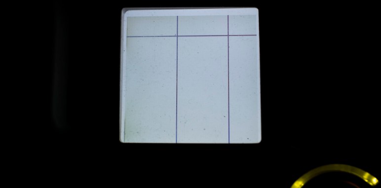
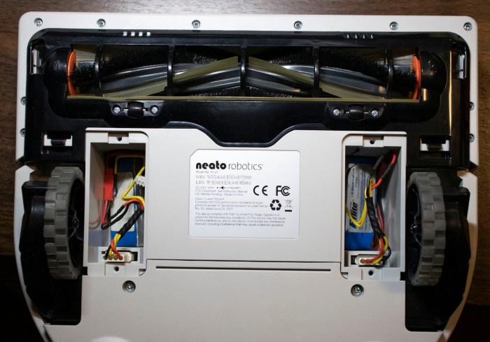
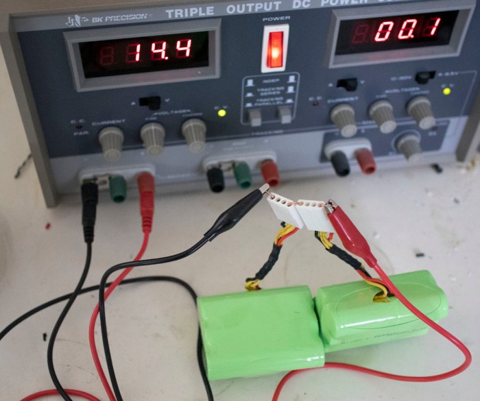
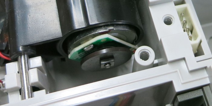
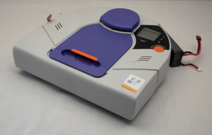
Using small batteries I hacked into existing battery bays, I was able to query sensor status and command individual motors. However, those small batteries were not powerful enough to run multiple motors simultaneously, which meant a full system test would not be possible until larger batteries are installed. At this point I could order some Neato-specific replacement batteries and have decent confidence it will work, but I would like additional confirmation before I spend money.

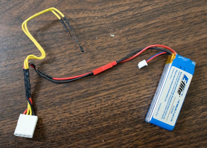
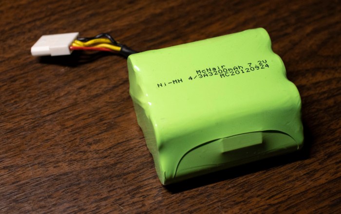
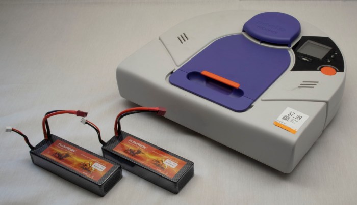
But I didn’t have any batteries that were more powerful and still small enough to fit within Neato vacuum’s existing battery bays. This meant batteries had to be installed externally. And if they’re going to be external, I might as well go with the biggest batteries I have on hand: those I purchased for Sawppy the rover.

But where could I install those batteries?

Neato XV-21 with two big power packs

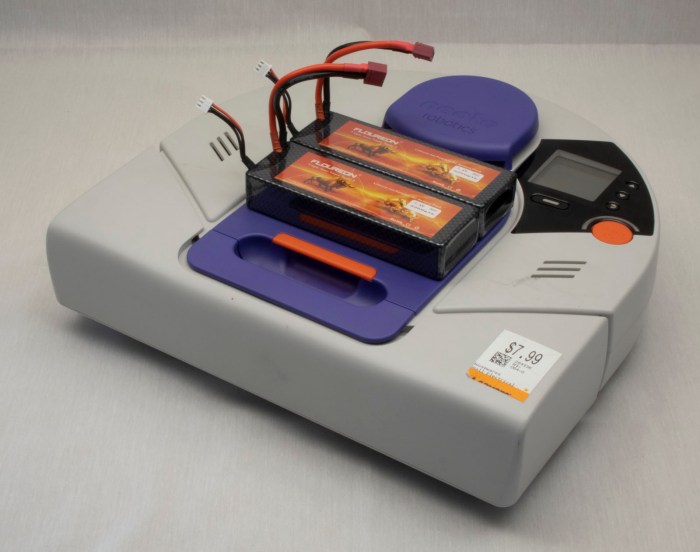
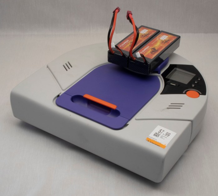
The most obvious place: is to put them on top of the dust collection bin. This is a popular location for Roomba battery retrofits, because it preserves weight balance and does not hinder Roomba operations. However, it won’t work for a Neato: this position blocks the line of sight for the laser distance scanner.

Neato XV-21 with two big power packs on top of dust bin

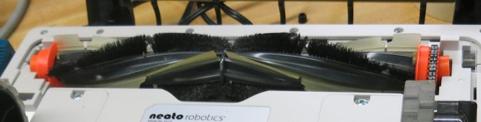
Installing the batteries on the front bumper would be out of lidar line of sight, and might help improve vacuum performance because their weight would help push the dirt brush roller into the ground. But this would change the behavior of front bumper which might confuse vacuum mapping algorithms, and using fragile batteries as your front bumper is never a good idea.

Neato XV-21 with two big power packs in front of bumper

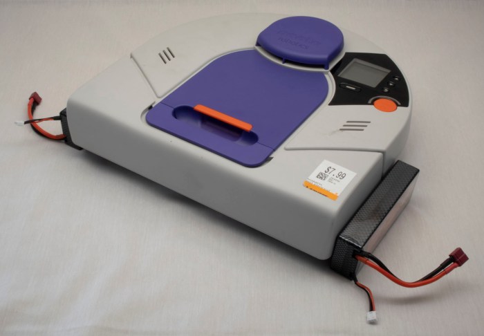
If we put batteries off to the sides, it preserves front clearance but now it interferes with side clearance. The vacuum would no longer be able to follow along walls closely to vacuum near walls if the batteries are attached to the sides.

Neato XV-21 with two big power packs along sides.jpg

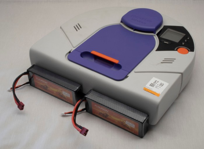
Installing behind the vacuum disturbs the weight balance – battery weight is now trying to lift the brush roller off the ground. The back is not flat, making installation difficult. And that circular shape is there for a reason – its clearance helps the robot turn in tight spots. Batteries install behind the robot would get bashed against obstacles as the robot turned.

Neato XV-21 with two big power packs behind

And obvious we don’t have any way to mount batteries on the underside of the vacuum, as there is only about 5mm of ground clearance. That exhausts all the potential directions we can go for external mounting.

Time to get creative.

Rethink top mounting, we recognize the problem is that we can’t block laser distance scanner’s line of sight. It looks out all around the top of the vacuum, except for one place: the raised protective cap above the lidar housing. Batteries mounted on top of that cap would not block laser scanner’s line of sight.

Neato XV-21 with two big power packs above lidar

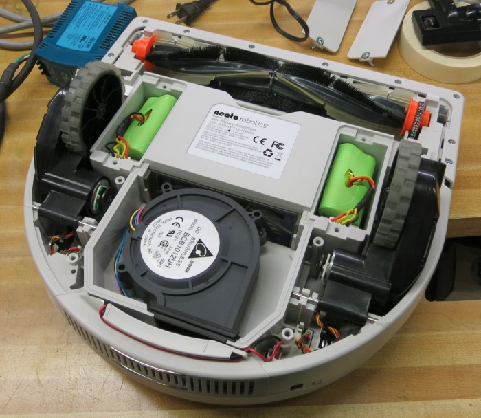
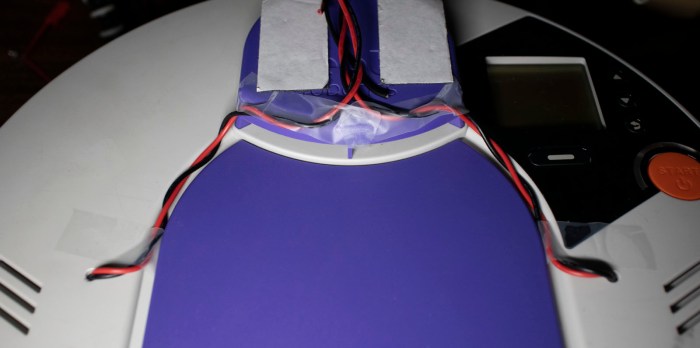
Wires were run from battery compartment, which required drilling two small holes. To keep the power wire out of sight of lidar, the wires were routed through existing grooves on top of vacuum body and then followed existing  support pillars for lidar housing. This way, the wires should not introduce additional blind spots.

Neato XV-21 wire routing for two big power packs.jpg

With this hack, the robot vacuum can run on my pair of Sawppy rover batteries, which are plenty powerful enough to run all vacuum systems simultaneously. Now this little Neato is alive and can run through a full vacuum cycle, verifying that all systems worked.

Neato XV-21 up and running with two big power packs

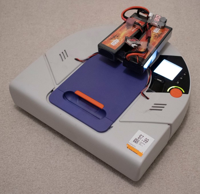
Obviously, this won’t be the final long term solution. For one thing, Sawppy wants its batteries back. For another, the additional height on top of the robot hampers its ability to get under furniture for vacuuming, and the exposed wires are vulnerable to tangling on protrusions. What we need next are batteries powerful enough to run a Neato and fit within existing battery bays.

Sending Commands to Neato XV-21 Via USB

I’ve managed to establish a serial connection to my Neato XV-21 robot vacuum’s USB port, putting it into test mode and querying sensor status. The next step is to start issuing commands to see if individual components respond. We left off on querying control panel user interface buttons, so the next test is to see if I can draw my own user interface on that control panel screen. Typing in help setlcd retrieved the following information:

SetLCD - Sets the LCD to the specified display. (TestMode Only)
BGWhite - Fill LCD background with White
BGBlack - Fill LCD background with Black
HLine - Draw a horizontal line (in foreground color) at the following row.
VLine - Draw a vertical line (in foreground color) at the following column.
HBars - Draw alternating horizontal lines (FG,BG,FG,BG,...),
across the whole screen.
VBars - Draw alternating vertical lines (FG,BG,FG,BG,...),
across the whole screen.
FGWhite - Use White as Foreground (line) color
FGBlack - Use Black as Foreground (line) color
Contrast - Set the following value as the LCD Contrast value into NAND. 0..63

This is enough to draw simple test patterns, but it isn’t enough for me to put up legible text prompts for users. This was not a surprise as I understand this mode to be a diagnostics console and not intended to facilitate a completely new UI like what I wish to do. Still, I can probably convey some simple if cryptic information by drawing horizontal and vertical lines. The valid range is 0-127 inclusive. And while vertical lines across that entire range are all visible, horizontal lines beyond 124 seem to go under bottom lip of display bezel and not visible.

setlcd bgwhite
setlcd hline 20
setlcd vline 50
setlcd vline 100


I’ve already played with turning the laser distance scanner on and off. The next most important thing to get running on this chassis are the drive wheels. If I can’t make the robot move using this interface, nothing much else matters. Here are the commands listed under help setmotor:

SetMotor - Sets the specified motor to run in a direction at a requested speed. (TestMode Only)
LWheelDist - Distance in millimeters to drive Left wheel. (Pos = forward, neg = backward)
RWheelDist - Distance in millimeters to drive Right wheel. (Pos = forward, neg = backward)
Speed - Speed in millimeters/second. (Required only for wheel movements)
Accel - Acceleration in millimeters/second.
(Used only for wheel movements. Defaults to 'Speed'.)
RPM - Next argument is the RPM of the motor.
Not used for wheels, but applied to all other motors specified in the command line.
Brush - Brush motor forward (Mutually exclusive with wheels and vacuum.)
VacuumOn - Vacuum motor on (Mutually exclusive with VacuumOff)
VacuumOff - Vacuum motor off (Mutually exclusive with VacuumOn)
VacuumSpeed - Vacuum speed in percent (1-100).
RWheelDisable - Disable Right Wheel motor
LWheelDisable - Disable Left Wheel motor
BrushDisable - Disable Brush motor
RWheelEnable - Enable Right Wheel motor
LWheelEnable - Enable Left Wheel motor
BrushEnable - Enable Brush motor
SideBrushEnable - Enable Side Brush Motor motor
SideBrushDisable - Enable Side Brush Motor motor
SideBrushOn - Enable the Side Brush
SideBrushOff - Disable the Side Brush
SideBrushPower - Side Brush maximum power in milliwatts

The first few attempts – using just individual commands – were met with either errors or no movement.

setmotor lwheeldist 100
No recognizable parameters

The first successful command that triggered movement was one where I specified three parameters on a single line: left wheel distance, right wheel distance, and speed.

setmotor lwheeldist 200 rwheeldist 200 speed 100

The robot moves! This is great news, but we still have two more motors to play with. First up is the brush roller: I had expected the motor to be a digital on/off affair, or maybe something I can command with a particular motor power level. I was quite pleasantly surprised it can be commanded to a particular RPM because it implied a more sophisticated closed-loop feedback control system.

setmotor brush rpm 750
Run Brush Motor @ 750 RPM

The final motor control for vacuum suction fan was a little frustrating. I had no issue turning it on with setmotor vacuumon and then back off with setmotor vacuumoff. But I haven’t yet figured out the right syntax to command it to spin at a partial power level.

setmotor vacuumspeed
Value required for option VacuumSpeed
setmotor vacuumspeed 50
No recognizable parameters
setmotor vacuumspeed 50%

Invalid Command: 'setmotor vacuumspeed 50%'

I’ll update this post if I ever figure it out, but for now it is enough that it spins.

With this set of tests, I have determined that all individual components are functional, but only in a limited context. The limitation is because I could power just one device at a time with the small batteries I have installed. What I want next is a full system test. And for that, I will need to install more powerful batteries.

Query Neato XV-21 System Status Via USB

With the experimental batteries in place, the computer boots up and stays up for longer than three seconds. I tried to run a vacuum cycle but that was too much for these batteries to handle, so for now I’ll stick with digital exploration starting with the standard UI to dump revision information on components inside this particular Neato XV-21 robot vacuum.

Neato XV-21 info

After that, it’s time to go exploring through its USB serial port diagnostics!

I went straight to the most interesting component: the laser distance scanner module. First I had to put my vacuum into test mode with testmode on. Followed by setldsrotation on to turn on the motor that sweeps the laser. And finally, fetch a set of laser distance data with getldsscan. This gave me a large set of numbers. According to the legend given in the first line of the response, a distance and intensity number per degree of sweep. Partial excerpt below:

AngleInDegrees,DistInMM,Intensity,ErrorCodeHEX
0,2378,82,0
1,2397,88,0
2,0,88,8021
3,2494,85,0
4,2505,82,0
5,2509,12,0
[…]
355,2289,99,0
356,2303,103,0
357,2303,99,0
358,2315,94,0
359,2367,91,0
ROTATION_SPEED,5.10

Future experimentation will determine what range of distance values are typical, similarly for intensity values. A quick web search failed to find a reference guide for error hex codes, but hopefully there’ll be a small set that I can infer from context. More exploration to come!

In the meantime, I repeated the getldsscan command to verify the values are getting updated. They were – I received a similar but slightly different set of numbers. Hooray! the most important sensor looks like it is functioning.

Next item on the exploration list: querying analog sensor values with getanalogsensors.

SensorName,Value
WallSensorInMM,63,
BatteryVoltageInmV,16120,
LeftDropInMM,60,
RightDropInMM,60,
LeftMagSensor,-2,
RightMagSensor,-3,
UIButtonInmV,3317,
VacuumCurrentInmA,0,
ChargeVoltInmV,132,
BatteryTemp0InC,34,
BatteryTemp1InC,31,
CurrentInmA,622,
SideBrushCurrentInmA,29,
VoltageReferenceInmV,1225,
AccelXInmG,-8,
AccelYInmG,-12,
AccelZInmG,1092,

I see three distance sensors – wall and two drop sensors, one in each front corner. It’s not immediately clear what “Mag” in left and right “MagSensor” referred to. Do they detect magnetic fields? Or are they measuring magnitude of something? Bottom three lines indicate the vacuum sensor suite includes a three-axis accelerometer which can measure in units of thousands of G, implied by a Z value nearly 1000 in this vacuum sitting on the floor. Remainder of the values are related to power management.

The 3-axis accelerometer values above from getanalogsensors partially overlap with results of getaccel. As the name indicates, this one is completely focused on accelerometer readings and includes results of additional calculation in the form of pitch and roll in degrees and a sum of acceleration vector.

Label,Value
PitchInDegrees, -0.64
RollInDegrees, -0.53
XInG,-0.012
YInG,-0.010
ZInG, 1.079
SumInG, 1.079

The list of digital sensor values from getdigitalsensorsis shorter, and for whatever reason, labelled in all capital letters.

Digital Sensor Name, Value
SNSR_DC_JACK_CONNECT,0
SNSR_DUSTBIN_IS_IN,1
SNSR_LEFT_WHEEL_EXTENDED,0
SNSR_RIGHT_WHEEL_EXTENDED,0
LSIDEBIT,0
LFRONTBIT,0
RSIDEBIT,0
RFRONTBIT,0

Here we can see whether the dustbin is installed, whether either or both wheels are at full extension, and it looks like there are four switches associated with the front bumper. The top line shows if a charging plug is connected, but that’s only one of many parameters around power management. Most of the rest are in getcharger.

Label,Value
FuelPercent,88
BatteryOverTemp,0
ChargingActive,0
ChargingEnabled,0
ConfidentOnFuel,0
OnReservedFuel,0
EmptyFuel,0
BatteryFailure,0
ExtPwrPresent,0
ThermistorPresent[0],1
ThermistorPresent[1],1
BattTempCAvg[0],33
BattTempCAvg[1],31
VBattV,16.03
VExtV,0.16
Charger_mAH,0

If I were to create my own control logic for driving my Neato around, the most important parameter here is FuelPercent. I’ll have to be responsible about not draining the battery too far, beyond that I can leave the rest in the capable hands of Neato’s existing battery management system. Speaking of power consumption, the biggest drains are the motors, and I can monitor them all with getmotors.

Parameter,Value
Brush_RPM,0
Brush_mA,0
Vacuum_RPM,0
Vacuum_mA,0
LeftWheel_RPM,0
LeftWheel_Load%,0
LeftWheel_PositionInMM,-1
LeftWheel_Speed,0
RightWheel_RPM,0
RightWheel_Load%,0
RightWheel_PositionInMM,-1
RightWheel_Speed,0
Charger_mAH, 0
SideBrush_mA,28

Not very exciting at the moment, because all motors are at a stop. I imagine these numbers will get more interesting once the robot gets underway.

One final discovery in inputs: when in test mode, the user interface buttons on the top of the robot no longer trigger their usual functions. I could check for status of all five buttons via getbuttons which implies I could use these buttons in my own projects without worrying that I’ll trigger the default vacuum behavior. Cool!

Button Name,Pressed
BTN_SOFT_KEY,0
BTN_SCROLL_UP,0
BTN_START,0
BTN_BACK,0
BTN_SCROLL_DOWN,0

But if I want to actually have my own user interface using those buttons, I would need to also display my own information on the LCD. Which brings us to phase 2 of playing over USB: start sending commands to see if components follow orders.

USB Serial Communication with Thrift Store Neato XV-21

My Neato XV-21 robot vacuum now boots up and stays running on a pair of old remote control helicopter batteries. This is a vast improvement over its comatose state when I found it in a thrift store. I pressed the start button to see if it’ll actually vacuum, but spinning up the motors drew too much current and aborted. Looks like these batteries are only good for probing electronics, which is still more than what I had before. And a good incremental step forward.

A few web searches on Neato technical details all pointed to posts on “Neato Robotics” forum on robotreviews.com. I guess this is where all the Neato robot tinkerers hang out. From this forum I learned of a tool for Neato maintenance that can help communicate with the vacuum as well as uploading firmware updates. Unfortunately, this forum also shared an update that Neato has taken these tools off their website. Without them, plugging the vacuum into my laptop running Windows would only result in a device without a driver.

On a lark, I rebooted my laptop into Ubuntu Linux and plugged in the vacuum. There were never any Neato drivers for this operating system, and I was curious what I could see via Linux tool dmesg.

[10547.714901] usb 1-1: new full-speed USB device number 25 using xhci_hcd
[10547.866228] usb 1-1: not running at top speed; connect to a high speed hub
[10547.876232] usb 1-1: New USB device found, idVendor=2108, idProduct=780b
[10547.876235] usb 1-1: New USB device strings: Mfr=1, Product=2, SerialNumber=0
[10547.876237] usb 1-1: Product: Neato Robotics USB v2
[10547.876239] usb 1-1: Manufacturer: Linux 2.6.33.7 with fsl-usb2-udc
[10547.881256] cdc_acm 1-1:2.0: ttyACM1: USB ACM device

Well, that was more straightforward than I had expected. The ACM in ttyACM1 here stands for abstract control model. The operating system sees a communication device where all control is handled by the device, and all I had to do is treat it like a serial port. It’s not a true serial port, but close enough the technical differences aren’t important right now. What matters is the fact that I can run minicom --device /dev/ttyACM1 and issue a simple call for help. We are in business! The channel has been opened to talk to a Neato vacuum brain and see what it says in return.

help
Help Strlen = 1792
Help - Without any argument, this prints a list of all possible cmds.
With a command name, it prints the help for that particular command
Clean - Starts a cleaning by simulating press of start button.
DiagTest - Executes different test modes. Once set, press Start button to engage. (Test modes are mutually exclusive.)
GetAccel - Get the Accelerometer readings.
GetAnalogSensors - Get the A2D readings for the analog sensors.
GetButtons - Get the state of the UI Buttons.
GetCalInfo - Prints out the cal info from the System Control Block.
GetCharger - Get the diagnostic data for the charging system.
GetDigitalSensors - Get the state of the digital sensors.
GetErr - Get Error Message.
GetLDSScan - Get scan packet from LDS.
GetMotors - Get the diagnostic data for the motors.
GetSchedule - Get the Cleaning Schedule. (24 hour clock format)
GetTime - Get Current Scheduler Time.
GetVersion - Get the version information for the system software and hardware.
GetWarranty - Get the warranty validation codes.
PlaySound - Play the specified sound in the robot.
RestoreDefaults - Restore user settings to default.
SetFuelGauge - Set Fuel Gauge Level.
SetMotor - Sets the specified motor to run in a direction at a requested speed. (TestMode Only)
SetTime - Sets the current day, hour, and minute for the scheduler clock.
SetLED - Sets the specified LED to on,off,blink, or dim. (TestMode Only)
SetLCD - Sets the LCD to the specified display. (TestMode Only)
SetLDSRotation - Sets LDS rotation on or off. Can only be run in TestMode.
SetSchedule - Modify Cleaning Schedule.
SetSystemMode - Set the operation mode of the robot. (TestMode Only)
TestMode - Sets TestMode on or off. Some commands can only be run in TestMode.
Upload - Uploads new program to the robot.

Replacement Battery Test for Thrift Store Neato XV-21

My Neato XV-21 vacuum couldn’t power on when I found it in a thrift store, and the problem (or at least, the first problem) was its battery pack: it could only deliver enough power to boot up the onboard computer and run it for about three seconds before its voltage dropped and the computer shut down again.

In order to assess the rest of the vacuum, I need to find a replacement power source. Since the actual condition of vacuum components are still unknown, I’m not inclined to spend money buying batteries specific to a Neato robot vacuum. The next experiment, then, is to wire up something out of batteries already on hand. I looked through my pile of batteries to see which would satisfy the following criteria:

  • Delivers roughly 7.2 volt power of a six-cell NiMH battery.
  • Fits within Neato battery compartment.
  • A pair of identical batteries, one for each bay.

The winner was a pair of batteries I had for my E-Flite remote control helicopter. The aircraft itself had long since been crashed and trashed, but I kept its batteries. Two cell lithium polymer batteries have nominal voltage of 7.4 volts, within operational range of 6-cell NiMH batteries. Physically they were small enough to fit within the battery compartment, but at 800 mAh their power capacity is too low for full vacuum operation. They were designed to deliver high power to fly a small helicopter toy though only for a few minutes. Ideally they can run the vacuum motors briefly to verify their operation, but mostly I just need them to run the Neato computer for more than three seconds.

To connect these batteries, I first disassembled the old tired original battery pack. Before disassembly, I noticed a rectangular bump visible in the battery pack. I had thought this was the thermistor but I was wrong. It appears to be a temperature safety fuse. There was also an over-current protection amperage fuse in the pack. NiMH cells are relatively safe but it’s still good to see additional safety measures inside these packs.


I needed the battery pack’s wiring harness for my battery experiment, so it was cut free. I kept the temperature monitoring thermistor and wired the positive and ground battery power wires to a JST-RCY connector that will mate with my E-Flite battery pack.

E-flite Pack for Neato Vacuum.jpg

Once soldered, I connected the pair of batteries and plugged them into my Neato XV-21.

Neato XV-21 with adapted E-Flite LiPo batteries

I was greeted by the same boot-up screen I saw before, but this time the screen stayed on instead of flickering off after three seconds. Now it’s time to try talking to the vacuum.


Thrift Store Neato XV-21 Batteries Can’t Hold a Charge

The batteries from a Neato XV-21 were found to be flat and possibly damaged. This would certainly explain why the little robot vacuum failed to power on in the thrift store where I found it. Since the thrift store didn’t have its associated charging base, my fallback was to leave its batteries to trickle charge (at 100 milliamps) overnight on a bench power supply.

The battery packs nominal voltage was listed at 7.2 volt per pack, so the voltage limit for charging the pair in series was set to 14.4 volts. Fully charged six-cell NiMH battery packs can be up to 9 volts each, for 18 volts total, but setting to 14.4 volts leave us with a bit of headroom in case these batteries didn’t behave as expected. This turned out to be a good idea.

Neato battery pack on power supply

When I checked in on the batteries the next morning, I saw voltage sitting at 14.4 and amperage had dropped to 40 milliamps. If all goes well, the voltage would be evenly divided across the two packs at 7.2 volts each. This was not the case: one battery pack (I’ll arbitrarily name it pack A from now on) was holding at 7.9 volts and the other (now designated pack B) at 6.5. If it weren’t for the headroom, we might have inadvertently pushed pack A beyond its limits.

At this point I got distracted by other events and left the batteries sitting for a week. Checking in from time to time, I measured their open circuit voltage and wrote them down. It was an unplanned test of the batteries’ self-discharge rate.

Pack A:

  • Overnight trickle charge: 7.9 Volts
  • After one day: 4.67 V
  • After three days: 4.44 V
  • After a week: 2.0 V

Pack B:

  • Overnight trickle charge: 6.5 Volts
  • After one day: 2.77 V
  • After three days: 2.68 V
  • After a week: 2.61 V

While it is normal for NiMH batteries to self-discharge over time, this observed discharge curve was far more severe than is acceptable. Looking at the voltage discharge behavior for pack A, it appears to have two almost-useless cells, three weak cells, and one good cell. Pack B behavior hints at four almost-useless cells and two good cells.

But even if they are unusable to actually run the vacuum, they are still better than dead weight: these batteries can hold a charge for a very brief period. So they’re reconnected to the power supply to trickle charge again. I don’t expect them to actually power any motors, but perhaps there’d be enough to power on the electronics for a short while. Hopefully long enough for me to assess if the rest of the vacuum is healthy.

After another overnight charge, I plugged them into the vacuum and pushed the power button. Good news: they did power on the electronics for a short while. Bad news: It only lasted for three seconds, far too short to assess anything else about the vacuum. But the vacuum computer did boot, and that’s enough motivation to keep going.

Attempt to Charge Battery of Thrift Store Neato XV-21

We’ve pulled the battery packs out of a Neato XV-21 found in a thrift shop. We’re pretty sure the red and black wires are battery positive and ground, but if so we expect to see a few volts across those wires. The fact we measured less than a volt indicates this battery is flat and may even be damaged. Well, at least this would be consistent with the fact it wouldn’t power on in the thrift shop.

Fortunately, rechargeable NiMH battery cells are hardier than lithium batteries and they might possibly revive with a charge. And even if they were permanently damaged, they are less likely to turn themselves into fireworks as damaged lithium batteries sometimes do. Since we read a nonzero voltage, none of the cells have failed as an open circuit. Some might have failed as a short circuit acting as a resistor dissipating energy but not holding the charge. With this unknown, we shouldn’t charge the batteries anywhere near as fast as we could if they were known to be healthy.

Neato battery pack on power supply

A bench top power supply was set to a maximum voltage of 14.4 volts and maximum amperage of 0.1 amp (= 100 milliamps). Using a piece of wire, the two battery packs were connected in series. (Which is where the 14.4 came from: adding up their nominal 7.2 volts per pack.) Once connected in series, they were connected to the bench top power supply and we watched the meters.

If we instantly hit maximum voltage and maximum amperage, it indicates a short circuit somewhere, possibly in a dead battery cell acting as a resistor turning that 1.44 watts into heat. Fortunately this did not happen. We hit the 100 milliamp limit immediately as expected and the voltage started rising, which is consistent with a battery pack trying to charge.

After a few minutes, we disconnected the power supply and measured battery pack voltage: they now measure a few volts, higher than before. This increased confidence that our positive/negative wiring guesses were correct and also proof at least a few cells can hold some amount of charge.

The batteries were reconnected and, for the first half hour, we periodically touched each of the cells to see if they were hot to the touch. Some of the cells were warmer than others, but none were alarmingly so. We’ll let the power supply continue slowly feeding the battery pack overnight and see how they behave.

Examining Battery of Thrift Store Neato XV-21

This Neato XV-21 robot vacuum did not power on when I found it in the thrift store. Now that I’ve verified there isn’t anything fundamentally broken or missing on the robot, the next thing is to try to charge its batteries. But since the thrift store didn’t have its charger, we have to go to plan B: Pull out the batteries and see if we can work with it.

The interior component packaging of this vacuum divides its battery into two packs, each in their own battery bay on either side of its dust collection chamber. These two bays are accessible from the bottom of the vacuum, each with a door that opened by unscrewing a pair of Philips screws. Each battery pack has a 4-wire pigtail terminating in a connector that plugs into the vacuum.

It takes quite a bit of force to remove the connector. One battery was removed without incident, but the other battery required so much force it actually broke something holding the vacuum side connectors to the vacuum body. Fortunately this appears to only be a minor mechanical annoyance and will not derail the project. At worse, we now have a connector that will rattle as the robot moves around.

Neato XV-21 battery pack

Once the battery pack was removed we could read its printed information, identifying itself as a nickel-metal hydride (NiMH) battery pack. The general shape implies six cells, and the stated nominal voltage of 7.2 is consistent with six cells in series. Each cell is rated with a capacity of 3200 milliamp-hours. I didn’t know what “4/3A” meant but a quick web search indicated it was the physical form factor (size) of the battery. “McNair” appears to be the name of a battery manufacturing company, and finally “MC20120924” probably meant this battery was manufactured on September 24th, 2012.

Attention then turned to the four-wire connector. Typical convention hints black is probably negative and red is probably positive. A voltmeter said there was less than a volt across those wires, which is not just flat but might also indicate damaged battery cells. The next question: What are the two yellow wires? It is something the vacuum control board would want to know about, and our hypothesis is that it is a thermistor to measure battery’s temperature. As an experiment to test this hypothesis, we put a ohm meter across the two yellow wires and warmed up the battery pack with our hands. We saw resistance change in response to temperature.

With some confidence the yellow wires are not directly involved in charging, it’s time to put a little bit of power across those red and black wires to see what happens.

Digging Into Thrift Store Neato XV-21

Of course, I didn’t buy a nonfunctional robot vacuum from a thrift store just to admire how clean it is. I bought it to see if it can be brought back to life. So out comes the screwdriver set and it’s time to dig into those non user serviceable parts inside. Fortunately Neato didn’t feel the need to complicate this effort with “security” bits that would only hamper resourceful hackers by a few seconds – they were straightforward Philips head screws. I had expected fine pitched machine screws, but they were actually coarse pitched screws that self-tap into plastic. This limits the number of times we can assemble and disassemble this vacuum before the screws become too loose to hold themselves in place, but that’s a concern for the future.

Neato XV-21 with bottom panels removed

There are three easily accessible panels. Two rectangular battery compartment doors each held by two screws, and a large semicircular panel held in place by four screws.

Underneath the semicircular panel is a large centrifugal (squirrel-cage) fan responsible for creating the suction that gives vacuum cleaner their name and purpose. The filter sitting in the back end of the dust bin is visible. Air would move past the filter, through the fan, and exhaust out the grating at the back. It would not have been surprising to find a coat of fine dust that made their way past the filter, but the fan compartment is pristine. Either the filter is far more capable than I give it credit for, or this vacuum was indeed barely used.

Neato XV-21 wheel encoder

On either side of the fan are motor gearbox assemblies for driving the vacuum around. The motor appears to be a commodity DC brushed motor, but it does have some sort of encoder mounted to its back. Looking at the circuit board we saw a single sensor, indicating this encoder can sense motor movement but not its direction: a full quadrature encoder would have had two sensors on the board.

Also visible behind the robot’s left wheel (right side of top picture) are wiring for external connectors:

  • Mini-USB for serial data, which would be extremely interesting if I could get the vacuum powered up.
  • Barrel jack for a charging adapter I don’t have.
  • Two thick metal wires to make contact with a Neato charging dock, which I also don’t have.

Given that the official chargers were absent from this thrift store purchase, the next step is to remove these two battery packs and see what we can do with them.

A Curiously Clean Thrift Store Neato XV-21

I went to a thrift store to take pictures, but came home with a Neato XV-21 vacuum that did not power on. At $7.99, it was a cheap gamble to see what might be usable in this robot vacuum cleaner. In my cursory in-store examination, it looked to be in good shape. After I took a little time for a closer look, I realized it was actually in even better shape than I had initially thought.

Super clean Neato XV-21

Of course, there’s no mistaking the vacuum for new. There is dirt in the dust bin and visible black smudges on top of the vacuum. But beyond that I found almost no other signs of wear. The exterior sides of this unit are clean, free of the scuff marks and other marring I associate with robot vacuum veterans. Although my experience are mostly with affordable models of Roomba and similar vacuums that perform a random walk through its environment, bumping into things along the way. The selling point of a Neato is its lidar for object avoidance, so the nearly pristine sides of may just be a result of excellent object avoidance and not lack of use.

Super clean Neato XV-21 brush

Its floor cleaning brushes show some dirt but is actually really clean. My own home vacuum would show more dirt than this after a minute of use. Brush roller drive belt looks to be in good shape.

At this point I’m still undecided whether this was a barely used robot vacuum or maybe the previous owner is just very meticulous about keeping their tools clean. The clean brush and dust bin certainly imply the former, but the latter is also quite possible as indicated by the presence of original protective plastic over the control panel. The previous owner was one of those people who did not remove plastic protective film that were meant to be removed, a mindset very different from mine.

Me? I peel that stuff off before I start taking this vacuum apart to examine its internals.

New Project: Neato Hacking

My ROS learning robot Phoebe was built mainly around a laser distance scanner module salvaged from a Neato robot vacuum cleaner. At the time I knew people were selling them for $50-$75 on Craigslist in varying condition, but I was content to pay $45 for just the laser scanner. It was all I needed for my own robot exploration purposes. I thought a full Neato vacuum might be fun to play with, but I have enough projects on my to-do list that I didn’t feel the need to go out and find one.

Unless when I do. I recently wrote a Hackaday article about bargain shopping in a thrift store, and I needed a picture to go with my article. I went into my local thrift store to take some pictures, but it was also an opportunity to practice what I preached. I spent most of my time in the electronics section and didn’t find anything I wanted to take home with me. On my way out the door, though, I took a glance at the kitchen electronics section and spotted this beauty: a Neato robot vacuum with a price tag of only $7.99.

Savers Neato XV-21 1600

It doesn’t power on, and external accessories were nowhere to be found: neither a wall wart charger nor its charging dock. But it looked to be in pretty good condition with only minor cosmetic blemishes on the exterior. Aside from the missing charger, all other major components appear to be present. But the purchase decision was based on the most interesting part: I looked inside the top bump to verify presence of a familiar looking laser scanner unit. If I all I get out of this $7.99 is a Neato lidar, I’ll be happy. If anything else worked, they would just be icing on the cake.

It’s a big question mark, but it’s one I’m buying to take home for a closer look.

SGVHAK Rover, Sawppy, and Phoebe at SGVLUG February 2019 Meeting

At the February 2019 meet for San Gabriel Valley Linux User’s Group (SGVLUG), Lan and I presented the story of rover building in our hardware hackers spinoff group a.k.a. SGVHAK. This is a practice run for our presentation at Southern California Linux Expo (SCaLE) in March. Naturally, the rovers themselves had to be present as visual aids.

20190214 Rovers at SGVLUG

We started the story in January 2018, when Lan gathered the SGVHAK group to serve as beta testers for Jet Propulsion Laboratory’s Open Source Rover project. Then we went through our construction process, which was greatly motivated by our desire to have SGVHAK rover up and running at least year’s SCaLE. Having a rover at SCaLE was not the end, it was only the beginning. I started building my own rover Sawppy, and SGVHAK rover continued to pick up hardware upgrades along the way.

On the software side, we have ambition to increase sophistication by adapting the open source Robot Operation System (ROS) which led to a small digression to Phoebe, my tool for learning ROS. Getting a rover to work effectively under ROS poses some significant challenges that we have yet to address, but if it was easy it wouldn’t be fun!

Since this was a practice talk, the Q&A session at the end was also a forum for feedback on how we could improve the talk for SCaLE. We had some good suggestions on how we might have a better smoother narrative through the story, and we’ll see what we can figure out by March.

Sawppy at Brawerman East STEAM Makers Fair

Sawppy’s publicity appearance today was at Brawerman East STEAM Makers Fair, a supercharged science fair at a private elementary school. Sawppy earned this invitation by the way of January presentation at Robotics Society of Southern California. The intent is to show students that building things is more than their assignments at their on campus Innovation Lab, there are bigger projects they can strive for beyond the classroom. But the format is, indeed, just like a school science fair, where Sawppy got a display table and a poster board.

Brawerman STEAM Makers Fair - Sawppy on table

But Sawppy is not very interesting sitting on a table, it didn’t take long before the rover started roving amongst other exhibits. The school’s 3D printer is visible on the left – a Zortrax M200.

Brawerman STEAM Makers Fair - Sawppy roaming

Sawppy was not the only project from grown-ups present. I admire the ambition of this laser cutter project undertaken by one of the parents. Look at the size of that thing. It is currently a work in progress, and its incomplete wiring were completely removed for this event so little fingers are not tempted to unplug things and possibly plugging them in a wrong place.

Brawerman STEAM Makers Fair - laser cutter

The center of this tables had some old retired electronics equipment that kids will be able to take apart. This was a huge hit at the event, but by the end of the night this side of the room was a huge mess of tiny plastic pieces scattered all over.

Brawerman STEAM Makers Fair - deconstruction zone

I brought my iPad with the idea I could have Sawppy’s Onshape CAD data visible for browsing, but it turned out the iOS Onshape app required a live internet connection and refused to work from cache. As an alternate activity, I rigged it up to show live video footage from Sawppy’s onboard camera. This was surprisingly popular with the elementary school age crowd, who got a kick out of making faces at the camera and seeing their faces on the iPad. I need to remember to do this for future Sawppy outings.

Brawerman STEAM Makers Fair - Sawppy camera ipad

After Sawppy was already committed to the event, I learned that a Star Wars themed art car was also going to be present. So I mentioned my #rxbb8 project which earned me a prime parking spot on the first floor next to the far more extensively modified “Z-Wing.” Prepare to jump to hyperspace!

rxbb8zwingcropped

(Cross-posted to Hackaday.io)

Sawppy at Space Carnival Long Beach

Sawppy at Space Carnival Long Beach

Space Carnival, held at the Expo Arts Center in Long Beach, California, welcomed Sawppy as one of several exhibits Monday afternoon. It turned out to be part of a week-long LEGO robotics camp for elementary school students. Most of the events are for campers, but the Monday evening Space Carnival was open to the public.

Since the focus is on LEGO, there were plenty of plastic bricks in attendance. The middle of the room had a big pile of bricks on a plastic tarp and kids were crawling all over the pile building their creations. Sawppy mostly spent time outside of the tarp, occasionally venturing on to some of the colorful game boards for LEGO robots to line-follow and other tasks.

Sawppy at Space Carnival Long Beach LEGO tarp

As usual, I handed controls over for kids in attendance to play with. Running over feet is still more popular of an event than I can hope to understand but, if it makes them excited, so be it.

Sawppy at Space Carnival Long Beach running over feet

Sawppy was not the only non-LEGO robot in attendance, there were also a selection of Star Wars licensed merchandise including this R2D2. I forgot if this particular unit was made by Sphero or Hasbro.

Sawppy at Space Carnival Long Beach R2D2

This event was not the first time I crossed paths with Barnabas Robotics, but it was the first time I got to speak with them beyond the standard sales pitch type of discussions. Since their business is STEM education for students K-12, they have a good feel of what type of material is appropriate for various age groups. It’s possible Sawppy can find a role in high school curriculum.

At the end of the night, the LEGO tarp cleared out enough for me to drive Sawppy across the field. Unfortunately I saw Emily’s tweet too late to replicate the movie clip she had suggested. Maybe another day!

(Cross-posted to Hackaday.io)

Sawppy Has A Busy Schedule This Week

Since the time I declared Sawppy version 1.0 (mechanical maturity), I’ve been taking my rover out to various events. From casual social gatherings to large official events to presentation in front of others who might appreciate my project. Sawppy has been a great icebreaker for me to start talking with people about their interests, and sometimes this leads to even more events added to Sawppy’s event calendar. This coming week will be especially busy.

Space Carnival

On Monday February 11th from 3pm-6:30pm Sawppy will be at Space Carnival, a FIRST Themed Event on Lincoln’s Birthday. Held at Expo Arts Center, a community space in Long Beach, CA. This event is organized by people behind local FIRST robotics teams. This year’s competition is titled “Destination: Deep Space” and has a very explicit space exploration angle to all the challenges. So even though Sawppy is nothing like a FIRST robotics competitor, an invitation was still extended to join the fun.

This event will be unique in that I had the option to be a roaming exhibit and I chose it for novelty. I think a rover who is roving will be much more engaging than a rover sitting on a table. It also means I will not be tied to a booth, so I could check out other exhibitors as I roam around with Sawppy. This eliminates the problem I had with Sawppy at DTLA Mini Maker Faire – I had to stay in one place for most of the event and couldn’t see what other people had brought.

On Wednesday February 13th Sawppy will join a STEAM Maker’s Fair at Brawerman East, a private elementary school. This is a small event catering to students and parents at the school. I believe the atmosphere will be similar to a school science fair, with exhibits of student projects. To augment these core exhibits, Sawppy and a few others were invited. The intent is to show that concepts covered in their on-campus Innovation Lab projects are just as applicable to bigger projects outside of their class.

And finally, on Thursday Februarh 14th Sawppy will be part of another SGVLUG presentation. A follow-up to the previous rover themed SGVLUG presentation, this will still set up background but will talk more about what has happened since our initial rover construction. This also serves as a practice run for a presentation to be given at Southern California Linux Expo (SCaLE) next month.

(Cross-posted to Hackaday.io)

SparkleCon Sidetrack: Does It Have A Name?

spool holder with two stage straightener 1600x1200

My simple afternoon hack of a copper wire straightener got more attention – both online and off – than I had expected. One of these came as a fun sidetrack to my Sparklecon talk about my KISS Tindie wire sculptures. As part of the background on my wire form project, I mentioned creating this holder. It kicked off a few questions, which I had answered, but I had the most fun with “Does it have a name?”

I gave the actual answer first, which was that I had only been calling it a very straightforward “wire spool holder with straightener” but I followed it up with an off-the-cuff joke “Or did you mean a name like Felicia?” I think I saw a smile by the person asking the question (hard to tell, he had a beard) and I also got a few laughs out of the audience which is great. I had intended to leave it at that, but as I was returning to my presentation another joke occurred to me: “Felicia will set you straight.”

Since my script was already derailed, I saw no reason to run with it: “Is there a fictional character who is a disciplinarian? That might be fitting.” and opened it up to the audience for suggestions. We got “Mary Poppins” which isn’t bad, but things went downhill from there. The fact is: the disciplinarian in a story is almost always a killjoy obstacle in our hero’s journey. Or worse, one of the villains, as in the suggestion of “Delores Umbridge” given by a woman wearing a Harry Potter shirt. My reaction was immediate: “No.” But two seconds later I remembered to make it a tad more positive: “Thank you, she is indeed a disciplinarian, but no.” Hopefully she doesn’t feel like I bit her head off.

After the talk, there were additional suggestions interpreting my second joke “Felicia will set you straight” in the sense of personal relationship preferences. This went down a path of politically conservative zealots who believe it is their public duty to dictate what people do in private. This direction of thinking never even occurred to me when I threw out the joke on a whim.

I think I’ll leave it at Mary Poppins.

Using LibPNG To Encode Spooky Eye Data

Sclera array and bitmap

Emily and I thought it would be cool to have the Spooky Eye visualization running on platforms in addition to Teensy and Adafruit SAMD boards. The first target: a Raspberry Pi zero. Reading through the project documentation and source code gave us a good idea how the data is encoded, but the best test is always to make use of that data and see if it turns out as I expected.

This would be a new coding experiment, so a new Github repository was created. I added the header files for various eyeballs then I started looking for ways to use that data. Since the header files are in C, it made sense to look for a C library to do something. I decided to output data to PNG bitmap files. Verifying the output looks correct would be as simple as opening the bitmap in an image viewer.

The canonical reference library for PNG image compression is libpng. Since I expect my use to be fairly mainstream, I skipped over the official documentation that covers all the corner cases a full application would need to consider. In the spirit of a quick hack prototype, I looked for sample code to modify. I found one by Dr. Andrew Greensted that looked simple and amenable to this project.

I fired up my Ubuntu 18.04 WSL and installed gcc and libpng-dev as per instructions. The sample failed to compile at first with this error:

/tmp/ccT3r4xP.o: In function `writeImage':
makePNG.c:(.text+0x36f): undefined reference to `setRGB'
collect2: error: ld returned 1 exit status

Since there were a lot of references to this sample code, I thought this wouldn’t be a new problem. A web search on “makePNG undefined reference to setRGB” sent me to this page on Stackoverflow, which indicated there was a problem with use of C keyword inline. There were two options to get around this problem: either remove inline or use the -Ofast compiler option to bypass some standards compliance. I chose to remove inline.

That was enough to get baseline sample code up and running, and modification begins. The first act is to #include "defaultEye.h" and see if that even compiles… it did not.

In file included from makePNG.c:20:0:
defaultEye.h:4:7: error: unknown type name ‘uint16_t’

Again this was a fairly straightforward fix to #include <stdint.h> which takes care of defining standard integer type uint16_t.

Once everything compiled, the makePNG sample code for generating a fractal was removed, as was the code to translate the fractal’s floating point value into color. The image data was replaced with data from Spooky Eye header files. If all works well, I should have a PNG bitmap. The first few efforts generated odd-looking images because there were bugs in my code to covert Spooky Eyes image array, encoded in 16-bit RGB565 format, to be written out in 24-bit RGB888 format. Once my bitwise manipulation errors were fixed, I had my eyeballs!

Looking Under The Hood Of Adafruit Spooky Eyes

Sclera array and bitmap

Adafruit’s Hallowing was easily the most memorable part of the 2018 Superconference attendee gift bag. Having a little moving blinking eye looking around is far more interesting than a blinking LED. It is so cool, in fact, that Emily has ambition to put the same visual effect on other devices.

Since the Hallowing was one of the headline platforms that supported CircuitPython, the original hope was that it would be very easy to translate to a Raspberry Pi. Sadly, it turns out “Spooky Eyes” is actually a sketch created using Arduino IDE for a Teensy board that also ran on the Hallowing.

As I found out in my own Nyan cat project for Superconference 2018 badge, modern image compression algorithms are a tough fit for small micro controllers. And just as I translated an animated GIF into raw byte data for my project, Spooky Eyes represented their image data in the form of raw bytes in a header file.

Adafruit always has excellent documentation, so of course there’s a page describing what these bytes represent and where they came from for the purposes of letting people create their own eye bitmaps. Apparently this project came from this forum thread. I was a little grumpy the Adafruit page said “from the Github repository” without providing a link, but the forum thread pointed here for the Python script tablegen.py.

There was a chance the source bitmaps would be on Github as well, but I had no luck finding them. They certainly weren’t in the same repository as tablegen.py or the Arduino sketches I examined. Still, the data is there, we just need to figure out what format would be most useful for putting the eye on another project.

As a first step, I’ll try to extract and translate them into a more familiar lossless bitmap format. Something that can be directly usable by more powerful devices like a Raspberry Pi. A successful translation would confirm I understand the eyeball data format correctly, which would be good to know for any future projects that might want to encode that data into different formats as needed for other devices.

KISS Tindies: Ace/Spaceman II

One of the scramble before Sparklecon was getting my KISS band back together. On the weekend prior to Sparklecon, the band went on tour in their first public appearance. The good news: they were very well received and people loved them! The bad news: Someone loved them so much they decided to adopt my Spaceman, taking him home without my permission. I was missing a member of the band.

I had already signed up to talk about the band for Sparklecon, and it would be a bit lame not to have the full band at my talk. This means making Spaceman II, but for that I would need another KISS Tindie PCB. Fortunately, Emily came to the rescue! She was also at Superconference and had also picked up a KISS Tindie PCB of her own. She generously donated her panel so I could rebuild my blinky band.

Emily KISS Tindie Panel.jpg

Emily had already soldered a pair of yellow non-blinking LEDs to her Spaceman. For the sake of consistency with the rest of my blinky band, those two LEDs were removed. Then I got to work rebuilding a wire frame body. Given the time crunch, I tried to skim a bit on details and initially started trying to make Spaceman’s guitar out of a single length of wire.

Spaceman 2 one piece guitar

I only got this far, though, before I decided it didn’t look good. I aborted and returned to multi-piece construction. It is more time consuming, but it conveys superior detail.

Spaceman 2 multi piece guitar.jpg

Unfortunately that aborted experiment put me further behind on schedule. This is not the time to experiment, I need to stick with known solutions. For the most part, I stuck with what I knew worked for the rest of this reconstruction.

Spaceman 2 complete

I’m sad that I lost my first KISS Tindie Spaceman, but this experience also gave me the opportunity to answer one question I was asked: How long does it take to build a wire frame body for a KISS Tindie? I honestly did not know because when I’m focused on a project like this I lose track of time. Bend wire, compare against drawing, repeat until the curve is right. Then solder that piece, and repeat the whole process for the next piece.

I had guessed maybe each Tindie would take 30-45 minutes. This time, I started a timer just before I removed the yellow LEDs and stopped it right after I took the above picture of a completed KISS Spaceman II. Total time: 2 hours 45 minutes. Even though this included the aborted single-wire guitar, my estimate was clearly way off!

But that time was well spent, I had the full band again for my Sparklecon presentation.

Party Bling in 30 Minutes: LED Blinky Collar

It’s good to have grand long term projects like Sawppy, but sometimes it’s nice to take a side trip and bang out a quick fun project. The KISS Tindies were originally supposed to be such a project but grew beyond its original scope. Today’s project had to be short by necessity. At less than 30 minutes, it’s one of my shortest projects ever.

Collar LED blinky final curved.jpg

The motivation for this project was an office party, but I didn’t know what the crowd was going to be like. My fallback outfit for such unknown is a long sleeved dress shirt and a sport jacket. If it turns out to be formal, I’ll be under-dressed but at least I’ll have a jacket on. If it turns out to be semi-formal I should fit in. If it is casual, I can take off the jacket. But these are people in the electronics industry, so there’s a chance I will find a room full of people wearing flashing LEDs. I decided, less than an hour before I had to leave, instead of my usual necktie I’m going to substitute a little bit of LED bling of my own.

The objective is to take the same self-blinking LEDs I used on my KISS Tindies and install them under my shirt collar. Since these LEDs can be obnoxiously bright (especially in dark rooms) the light will be indirect, bouncing off fabric underneath my collar. This way I don’t blind whoever I’m trying to hold a conversation with.

When I bought the self-blinking LEDs for the KISS Tindies project, I bought a bag of 100 so there’s plenty left to play with. For a battery holder I’ll use the same design I created for the Tindies out of copper wire. There’s no time to 3D print a structure, so I’m just going to use paper. Copper foil tape will form circuitry on that sheet of paper. Here’s the initial prototype. I folded the paper in half to give it more strength. I had also cut out a chunk of paper to help the battery holder stay in place.

collar led blinky prototype parts

Assembling these parts resulted in a successfully blinking LED and good enough to proceed.

collar led blinky prototype works

The final version used a longer sheet of paper. I measured my shirt collar and cut a sheet of paper so the ends would sit roughly 3mm inside the collar. This was longer than a normal sheet of paper so I had to pull a sheet of legal size paper out of my paper recycle bin. I think it was the legal disclosure form for a pre-approved credit card offer.

collar led blinky final

The LEDs sit a few centimeters inside the paper’s edge. The other side of the paper had extra copper tape to shield the light from shining through. I wanted the light to reflect inside my collar, not show through it. The first test showed a few circular spotlights on my shirt, so I added a sheet of Scotch tape to diffuse light. Once I was happy with the layout of this contraption, I soldered all components to copper foil for reliability.

Less than 30 minutes from start to finish, I had a blinky LED accessory for my shirt.

collar-led-blinky

As it turned out, there was only one other person wearing electronics in the form of some electroluminescent wire. My blinky LED collar was more subtle about announcing itself, but they were noticed by enough people to make me happy.

(Cross-posted to Hackaday.io)