TT Gearbox Motor Wire And Capacitor

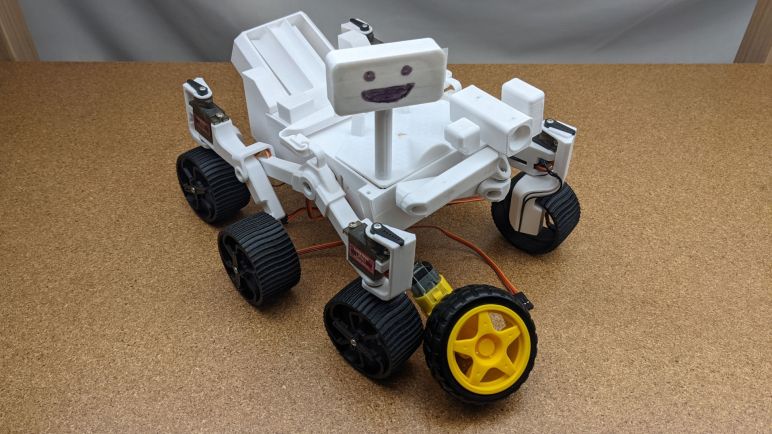
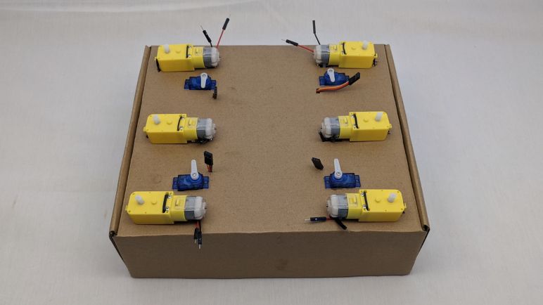
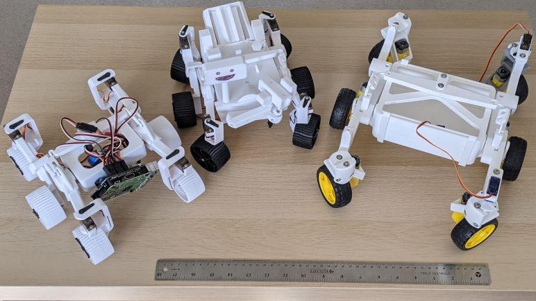
Micro Sawppy rover control board has evolved to a perforated circuit board with soldered connection (and a few bonus features like provision for voltage monitoring.) Every time I soldered wiring to support another motor, I tested it on my cardboard box rover testbed solving any problems that were exposed by the testing. Once all six wheels are turning and four corner steering servos moving, I was eager to install it in Micro Sawppy Beta 3 (MSB3) and see it move.

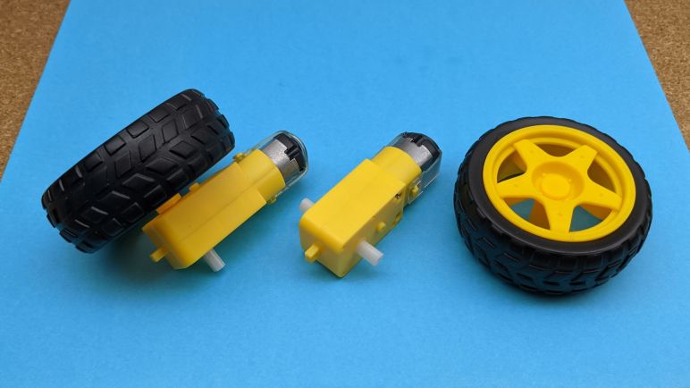
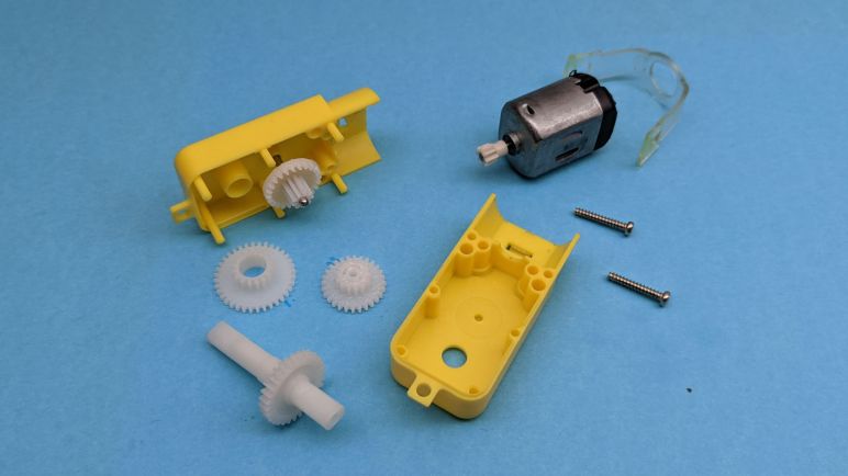
I didn’t want to disassemble MSB3 when I wanted to build a cardboard box rover test bed, so I bought some more TT gearmotors from a different vendor(*) to install in my cardboard box. It was the new lowest bidder of the day, and these motors came with the convenience of wires pre-soldered to the motors. The TT gearmotors on board MSB3(*) didn’t come with wires and I would have to solder them myself before I can drive MSB3 around.

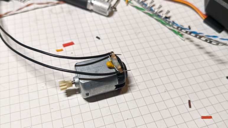
One thing I noticed about the motors with convenient wires is that it didn’t have noise-reduction capacitors. They’re usually absent from simple toys, but anything with electronics usually put capacitors on these motors to avoid glitching the some other part of the circuit. They are certainly considered essential when the device also has any kind of radio communication. The remote control hobby world is where I first learned of their importance, some facilities wouldn’t even let you run your vehicle if it was missing these capacitors, because of the risk it would cause interference with others at the facility and not just your own vehicle. I’m not worried about that in the immediate term. Since the cardboard testbed would always be wire tethered sitting on a tabletop, I didn’t feel compelled to add capacitors. But MSB3 will care about radio noise so I followed Pololu recommendations for adding noise reduction capacitors.

There are three options: a single capacitor across the terminals, or two capacitors from each terminal to the case, or combining both for the best noise reduction. The last time I tried soldering to the case of these little motors, I melted white plastic from the endcap and destroyed the motor. I then tried to remove the plastic part for soldering, but they were only held by bent tabs of metal from the case and they broken off making it impossible to reinstall and again destroying a motor. So in the interest of not destroying motors, I’m going with the simplest option of a single capacitor across the terminals to get MSB3 moving.


(*) Disclosure: As an Amazon Associate I earn from qualifying purchases.

Interactive MCPWM Duty Cycle Explorer

I started exploring TT gearmotor response to different duty cycles by editing MCPWM parameters in source code, compile with those new parameters, and uploading the results to my ESP32 motor control test bench board. It took only three cycles of this process before it was painfully clear I needed a better way. So I copied an excerpt (the joystick and MCPWM portions) of my ESP32 Sawppy control software out to a separate test program in order to interactively explore TT gearbox behavior under different duty cycles.

This test program only dynamically varies the duty cycle, not the PWM frequency. I’m running my program at a PWM frequency of 20 kHz. There may be an annoying whine audible to dogs and newborns, but it’s comfortably above my not-spring-chicken range of hearing. A brief test established that these TT gear motors behave differently at lower PWM frequencies. The most consequential effect is that I could turn them at a lower minimum speed. Still not rock-climbing slow, but there’s definitely an effect. I don’t have enough electrical engineering background to understand why I have more torque with lower PWM frequency, so I’ll have to come back to this topic later to find an explanation for my observation. In the meantime I’m insistent on 20 kHz PWM because I don’t like to hear the whining.

In my test program I didn’t have a real need for analog control, so the joystick was effectively turned into a direction pad. Pushing one direction increments duty cycle, pushing the opposite decrements it. The orthogonal axis adjusts the increment rate, so I can adjust in duty cycle increments of 10%, 1%, and 0.1%. In order to test startup power, I could press down on the stick to trigger its associated button. This button toggles motor power on and off. This program is only useful when connected to serial monitor because the increment rate and the current duty cycle are displayed via text sent over serial link. I plan to use this tool again once Micro Sawppy is rolling on its own wheels, in order to update speed-to-duty cycle mapping to reflect realistic loads on the wheels rather than unloaded spinning in the air.

In theory it should be possible to have this tool as a part of Sawppy ESP32 control code instead of a separate project. I would have to set up some sort of conditional compilation mechanism so I could toggle whether to compile standard Sawppy control or this duty cycle explorer. However, I don’t see any particular motivation to perform this work today so until I see a benefit, I’ll leave that integration task on the to-do list for the future. With some working PWM duty cycles in hand I can start putting them to work with ESP32 GPIO pin assignments.


[ This test program is publicly available on GitHub. ]

Exploring TT Gear Motor Speed Range

I wrote my ESP32 Sawppy rover chassis Ackermann geometry code to output calculated wheel speeds and steering angles in an implementation-neutral (but not similar to ros_control) way. Wheel speeds were specified in meters per second of desired ground travel speed, so the next step is to translate that into DRV8833 MCPWM control signals driving TT gear motors.

This conversion will be some kind of mapping from desired wheel travel velocity to PWM duty cycle. Without closed-loop control, I knew the mapping would not be accurate, but maybe it’ll close enough to be acceptable at this price point. I’m not sure how much of a load will be borne by each rover wheel yet, so the first draft of this mapping will work with the wheels spinning freely in air without load. Since a single DRV8833 can drive two motors, I drove a pair of TT gearmotors with the same electrical PWM parameters. I was not surprised to find that they had slightly different speeds. It’s not even a consistent ratio: one motor was faster at full power, while the other was faster at low power. Looks like the error bars on my mapping are getting longer and longer with each discovery!

For the sake of getting some numbers as a starting point, I estimated unloaded wheel travel speed at 6V to be approximately 0.6 m/sec. With this, I’m cautiously optimistic that Micro Sawppy rovers running on TT gear motors will be able to keep up with Sawppy V1 with its much larger diameter wheels. However, they won’t have the same performance at the low end. Unloaded, these TT gearmotors could turn as low as 15cm/sec, but just barely. Any slower than that and the motor couldn’t overcome internal gearbox friction. Such behavior implies these little rovers wouldn’t be much good for low speed rock climbing. This initial experiment found that TT gearmotors maximum speed isn’t very fast, and their minimum speed isn’t very slow. But it’s still an open question whether they are “good enough” for the sake of making an affordable micro Sawppy rover. I already know I need to revisit this speed range exploration once the rover is running on its wheels, so I wrote a tool to make that process less painful.

Micro Sawppy Rover Cardboard Box Testbed

Proving that I could control DRV8833 DC motor driver IC using an ESP32 was the final piece of the foundation I knew I needed before I seriously start building a micro Sawppy rover brain on an ESP32. During my development of this software, I will need a physical chassis to test code on. While I could go straight to my Micro Sawppy Beta 3 (MSB3) chassis, doing so has the risk of breaking physical robot hardware. Anything from a servo moving beyond intended limits, to embarrassing mistakes like driving the rover off the table.

A safer option is to have a representative testbed with fewer risks than a physical robot. For my original Sawppy rover, I removed all ten LX-16A serial bus servos and laid them out on a table. I found that a line of servos wasn’t very good at conveying system behavior, since I had to do some mental spatial transforms in my head to interpret those servo movements. Some bugs slipped through this process because I made mistakes in my mental visualization. From that experience I thought it would be better to have a testbed that better represented the physical layout of the rover chassis, and this is an opportunity to put that idea to the test.

In line with my recent discovery of cardboard for mockup purposes, I pulled a cardboard box from my paper recycle bin. I turned the box inside-out to give me some clean note-scribbling surfaces, plus I’m not advertising that product on this site anyway. Holes were cut in the cardboard so I could use twist ties to fasten six TT gearmotors in the same relative location as they would be on a rover. I also cut four rectangular holes for the steering micro servos. Since I cut those holes by hand, the imperfections of the manual cut gave the servos enough friction to sit in place without any fasteners.

Wires for all of these components went into the box, and small holes were cut so they could poke through to this top surface. This routing keeps all excess lengths of wire out of my way making for a neater work area. The ESP32-based control board, whatever it ends up being, should fit in the center area I kept clear for it. Excess wire isn’t the only thing I kept in the box, it was also a convenient place to store all the related auxiliary pieces related to the project. Each micro servo has a plastic bag with spare control horns as well as their mounting screws not needed for the testbed. And each gearmotor came with a wheel that’s not strictly necessary for the testbed. There’s a chance I’ll want these wheels later, to better visualize relative rotation velocity of the wheels. If that should occur I know where to find the wheels: they’re in the box!

But first I need to get started with Sawppy ESP32 software.

Micro Sawppy Beta 3 Wheel

The major motivation to build Micro Sawppy Beta 3 (MSB3), leaving MSB2 behind, was the increasing complexity of MSB2 wheels and I wanted a rover that is simple to build. Switching to using commodity TT gearmotor plus its associated wheels for the rover’s six wheels goes a long way. By using a gearbox that is already designed to support and drive a matching wheel, we eliminate custom modification and any worries about robustness of said modifications.

When I looked inside a TT gearbox I didn’t see any ball bearings, but I did see support structure that should suffice for a rover at this scale. At a very minimum, the rover would be as robust as every other robot design that use these wheels.

But like everything in design and engineering, there are tradeoffs. The biggest disappointment (and why I was reluctant to use these things to begin with) is that poor ground clearance. Comparing MSB3 against MSB2 and MSB1, we see ground clearance has degraded with iteration. There were good reasons to take each of these steps but it’s not the direction I wanted to go. Even with feedback that this feature isn’t ranked highly on many other people’s rover builds. Fortunately(?) I think this is as far as I have to compromise on this topic, at the moment I don’t know of anything that might further degrade clearance for future rovers.

Another problem is the fact these wheels don’t much resemble real Mars rover wheels. I was really proud of Sawppy’s wheel design and how I was able to scaled down for MSB1 and MSB2, but now I’m leaving them behind. While there’s the possibility to replace these generic wheels with 3D printed rover wheels, it would only be cosmetic. Given the geometry here, I don’t see a good way to restore functional ground clearance. But at least these wheels come with rubber tires, which was one of the biggest non-Mars-authentic feature requests for Sawppy.

A TT gearbox offers three attachment points. Two near the motor and one at the opposite end. While it would be most robust to use all three points, for MSB3 I decided on simplicity and used only the two close to its motor. The mounting bracket is angled to meet up with the steering axis, which is aligned with the middle of the wheel so the wheel could pivot in place.

Micro Sawppy Beta 3

Gaining a basic understanding of how to use the L298N module to control DC motors was an important confidence booster for modifying my little rover plans: Switch the rover’s six-wheel drive from micro servos modified for continuous rotation to a different approach: TT gearmotors that are designed from the start to drive wheels. They even come with one of the most frequent Sawppy requests: soft rubber wheels that are expected to have better traction on earthly surfaces. Steering the little rover’s four corner wheels remain the duty of micro servos, which would be doing their designed job of rotational position actuators.

The first rover chassis to emerge from this new plan is Micro Sawppy Beta 3 (MSB3) shown here next to its predecessors MSB1 and MSB2. Changing the wheel drive mechanism has a huge impact on the overall design, as this family portrait shows. A new rocker-bogie suspension implementation is the focus here, relegating the body back to a simple box as it was on MSB1.

The next few posts will cover some of the highlights of mechanical design changes for MSB3. Changing the wheel drive motor required a completely new steering knuckle design for the corner wheels. Which became an opportunity to design a multi-piece mechanism that would allow me to quickly adjust steering trim at mechanical level. Increasing the number of parts does make the mechanism more complex, but I am optimistic it would actually prove to be easier to build. MSB3 also represented a new way to use 623 bearings that hopefully eliminates the sensitivity to tightening torque. And the revamped rocker features an improved adaptation of the real rover’s rocker deploy pivot allowing the rover to fold up for transport. And finally, the differential linkage is a further evolution of using 3D printing to avoid having to scour remote control hobby catalogues for an adjustable suspension turnbuckle.

This tour of MSB3 starts at the same place as its predecessors, from the wheels. Then we’ll work our way up.

Trying Generic L298N Driver Board

I started researching using a L298 as motor driver because it is an established known quantity. After looking over its specifications, I realized it is not the best match for the TT gearbox DC motors I plan to use: the L298 is specified to work anywhere from 4 to 45 volts, but the little 130 DC motors used in a TT gearbox are usually listed with a nominal operating voltage of three to six volts. I should be able to avoid damaging the little motors as long as I keep the PWM duty cycle low. So I’ll continue investigation. Even if these aren’t the best drivers to use for my micro Sawppy, they might be useful for larger motors in larger Sawppy rovers.

During my research of L298 I came across reference to an Arduino motor control shield built around one of those drivers. It looks great, but a single shield with a single L298 can only drive two motors at different speeds. A six-wheel drive rover will have six motors. I could pair up front and back wheel motors if my rover chassis is front-back symmetric, but that still requires four different speed controls. I looked to see if the Arduino shield is stackable, but unfortunately the motor control pins are fixed so stacking them would only result in more motors running at the same two speeds.

Both Adafruit and Sparkfun appears to have moved beyond the classic L298 for their motor driver boards. I’ll look at those drivers modules later, for now I’m focusing on L298 so I headed to the cutthroat market of lowest-bidder generics, just as I looked there for my micro-servos and TT gear motors. A query for L298 on Amazon (*) returned many vendors all selling what looks like clones of the same product. A pattern repeated on AliExpress as well. I purchased from the Amazon lowest bidder du jour (*) for a closer look.

And just like with micro servos and TT gear motors, I couldn’t find much on the history of this particular driver module design. Somebody must have built and sold the first one, but now that it has since been copied infinitely I had no luck finding the source. Since this has become a generic fungible item, none of the vendors I checked bothered to supply documentation. They probably assumed a people can find it online somewhere and I’m sure I could. However, I’ve made a conscious decision not to. As an educational exercise I’ll try to decipher this module on my own.

Alrighty, what’s on this thing?


(*) Disclosure: As an Amazon Associate I earn from qualifying purchases.

TT Gear Motor Teardown

Commodity TT gearmotors became the center of my attention once I decided to switch to using DC motors for driving wheels on my little Sawppy rover project. Where did this form factor come from? Why do people call them TT? Why are most of them yellow? I don’t have answers to those historical questions, but I will see if I can build a little rover with them.

The adventure starts with buying a batch and taking one apart to see what’s inside. I’m not sure if the commodity TT gear motor market has diversified implementation like the micro servo market. If this experiment with TT motors go well, I expect I’ll buy more batches in the future for more little rovers and I’ll open those up to look for differences. Right now I could only speak to this one.

Externally, we see three mounting points. Two mounting holes go through the entire gearbox, next to the two screws holding the gearbox together. A third mounting hole is on a thin tab at the end opposite from the motor. There are two attachment points to the output shaft, which appears to be symmetric and have identical detent patterns. Turning the output shaft by hand, I can see the other output shaft moves in sync, but that doesn’t necessarily mean it is a single piece.

While the output shafts appear symmetric, the rest of the gearbox almost but not quite symmetric. The motor is offset by a little over a millimeter away from the camera in these pictures. On the side facing the camera, we see a little nub above the axle, whereas its opposite side is smooth.

The motor is held in place by a band of clear elastic plastic held by hooks molded into the gearbox exterior. In this particular unit, the clear plastic has partially melted into the yellow plastic and had to be peeled off with pliers before I could stretch them for removal. Once the clear plastic is removed, the motor can slide out. (To release just the motor, it is not necessary to remove the two screws seen in this picture.)

The motor looks very much like a commodity form factor used in many battery-powered toys. In disassembly and hacking circles I frequently see it referred to as “Mabuchi motor”. But just like “JST connector” this is not precise enough. Mabuchi Motor Company has a large product line, most of which aren’t this thing. I found references to this sized motor as FA-130, but with such commoditization I’m certain the majority aren’t genuine Mabuchi products. There’s certainly no Mabuchi logo on this particular motor.

What’s important for the purposes of project creation is that this is a common form factor. And thanks to its use in products like the Tamiya Mini 4WD product line, we can get motors with a wide range of performance characteristics. Same external motor dimensions, but different tradeoffs for torque vs. max speed, etc. At least that’s the theory, I won’t know for sure until I try buying one of those Mini 4WD Hop-Up motors and try installing it in one of these gearboxes.

With the two screws removed, I could open up the gear box and see the gears inside. Pulling the gear train apart, I find four separate components.

My first observation is that all the gears appear to have different diameters. I’ve seen a few TT gearbox modding guides that claim I could select different gear ratios by flipping some gears around, but I don’t see how that is possible when the gears are all different diameters. I’m either overlooking something, or this unit is the wrong variant for that mod to work.

My second observation is that the output shafts poking out on both sides of the gearbox are indeed part of a single piece shaft. There are no ball bearings here but at least they are supported on both sides of the shaft. However, since the output shaft is very clearly asymmetric, I should pay attention to which side is used as the main weight bearing member. Looking at this teardown, I have a clear preference for the side further from the camera in these pictures. That side of the shaft has far more support, in the form of a plastic tube approximately 8mm long. The side closer to the camera (and laid flat against the surface in these pictures) has only a thin wall of plastic for support.

I wonder if there’s a situation where the opposite is true? Perhaps when torque is a concern and we want to be closer to the final output gear, in order to minimize torque imposed on the shaft? I don’t think that’s likely at this power level, but I’ll keep an eye open for the possibility.

I didn’t need to take apart this DC gearmotor to use it, but having seen its insides I feel more confident approaching the task of mechanically adapting it to rover duty. In the meantime, I have a parallel adventure of learning how to drive these motors electrically.

Notes on TT Gear Motor

I’m now looking at DC motor with gearbox for rover locomotion. I started my little rover project with the intention of using micro servos all around. For six wheel drive, they would be modified for continuous rotation. This is a tradeoff: we gain a servo’s existing H-bridge circuit with proportional control, but we take the risk of putting a physical load it is not designed for. Unfortunately I found a problem with my Beta 2 chassis: some of these inexpensive micro servos lack useful proportional control. If I can’t depend on a servo’s existing circuitry, I might as well switch to a different gear motor: the TT gear motor.

Similar to micro servos, the TT gear motor has become a commodity item. Made by lots of manufacturers and sold by lots of vendors. (*) Where did this design start, why is it called “TT”, and why are they all yellow? Sadly I found no satisfying answers to these historical questions. Searching on the internet was made difficult by their name, which tends to return results relating to a real car, the Audi TT. Did this gearmotor start life in a toy car modeled after the Audi TT? So many questions, so few answers.

The only bit of information I found hinting at a source was a mention on the product page for Solarbotics Gear Motor 3 which superficially resembles the TT gearbox. However, it is not called TT there, and it is not yellow, so clearly this is not the entire history.

Based on the original design by Mark Tilden for use in the B.I.O.Bugs & RoboSapien, these motors are the next generation with a variety of improvements such as dual output shafts and a lower current motor.

Product Description for Solarbotics Gear Motor 3

I found no corroborating information beyond that snippet of text.

Anyway, back to the device itself: we can see it uses a much larger motor than the one inside a micro-servo, which may be (but not necessarily) more powerful. A larger gearbox also implies larger and more durable gears. But the most important part is that these are used to drive the wheels in a robot kit. For example, Servo City’s Runt Rover series use this type of motor for their wheels, albeit in black instead of yellow. The fact they are designed for wheels makes me more comfortable I’m using mechanical parts for their designed task. Which was a worry for (mis)using continuous rotation micro servos for micro Sawppy beta 1 and 2 rover wheels.

And thanks to the popularity of this form factor, we have an ecosystem of variants in the same size and fit the same axle. The standard gear ratio is 1:48, but other gear ratios are offered for those who want to make different tradeoffs between speed and torque. High torque gearboxes need to more durable, but not to worry, this form factor with higher gear ratios are also available with all metal gears in products like Adafruit #3802.

A particular wheel design is most commonly associated with this gearbox, but there are alternate wheel choices to fit onto that axle. The axle is large and simple enough that we can probably FDM 3D print our own wheels as well. That output shaft is symmetric so some robot kits put two wheels, one on either side. But I usually see the other end either left unused or used for an encoder wheel for low resolution wheel odometry. (*) If we want higher resolution encoders, we can buy variants with an encoder on the motor.

This all looks very promising so I bought some TT gearmotors for experimentation. First order of business: take one apart to see what I’m working with.


(*) Disclosure: As an Amazon Associate I earn from qualifying purchases.

DC Gearmotors For Little Sawppy Rover

Based on my experience modifying wheel drive motors on my little rover Micro Sawppy Beta 2 (MSB2), I decided it was trending towards a rover design that would be too difficult to work on. If I, as the designer of MSB2, am tearing my hair out struggling with wire routing, how can I realistically expect beginners to work with this thing? I think MSB2 succeeded at being really cute, unfortunately the beauty was only skin deep and its core difficulties are not what I want.

But while I stopped further work on MSB2, I wanted to continue the task I was in the middle of: trying out the idea of using DC gearmotors. The micro-servos I used in MSB2 taught me that my original idea for driving little rover wheels were unreliable. While we could modify micro servos for continuous rotation, there’s no guarantee their control circuits would give us usable speed control. Sometimes they don’t! In order to guarantee a little Sawppy rover could be reliably built, I must take motor speed control into my own hands.

This decision started when I removed all electronics from MSB2 wheel servos, using them as just a motor with a gearbox inside a micro-servo sized enclosure. (FYI Adafruit product #2941 is exactly like this, no modification required.) Even though I’m throwing out half the device, it’s still a very inexpensive way to obtain a small DC gearmotor thanks to the large volume market of generic commodity micro servos. But if we are going to use a small high volume commodity DC gearmotor to drive little rover wheels, there’s actually a better option: TT gear motors.

These DC motor + gearbox units are ubiquitous like generic micro servos, mass produced by many manufacturers at high volume and low cost. It is available as Adafruit #3777 but they are definitely not the only retailers. (*) I first learned they existed when I saw them pop up in multiple projects submitted to a Hackaday contest, and a little background research unveiled how widespread they were.

Since I’ve decided to add the complexity of DC motor driver modules, these TT motors immediately jump to the top of the list. Unlike micro servos, TT gear motors were designed for driving wheels.


(*) Disclosure: As an Amazon Associate I earn from qualifying purchases.